EP0127301B1 - Improved positive battery plate - Google Patents
Improved positive battery plate Download PDFInfo
- Publication number
- EP0127301B1 EP0127301B1 EP84302574A EP84302574A EP0127301B1 EP 0127301 B1 EP0127301 B1 EP 0127301B1 EP 84302574 A EP84302574 A EP 84302574A EP 84302574 A EP84302574 A EP 84302574A EP 0127301 B1 EP0127301 B1 EP 0127301B1
- Authority
- EP
- European Patent Office
- Prior art keywords
- lead
- paste
- positive
- electrolyte
- tin oxide
- Prior art date
- Legal status (The legal status is an assumption and is not a legal conclusion. Google has not performed a legal analysis and makes no representation as to the accuracy of the status listed.)
- Expired
Links
Images

Classifications
-
- H—ELECTRICITY
- H01—ELECTRIC ELEMENTS
- H01M—PROCESSES OR MEANS, e.g. BATTERIES, FOR THE DIRECT CONVERSION OF CHEMICAL ENERGY INTO ELECTRICAL ENERGY
- H01M10/00—Secondary cells; Manufacture thereof
- H01M10/06—Lead-acid accumulators
-
- H—ELECTRICITY
- H01—ELECTRIC ELEMENTS
- H01M—PROCESSES OR MEANS, e.g. BATTERIES, FOR THE DIRECT CONVERSION OF CHEMICAL ENERGY INTO ELECTRICAL ENERGY
- H01M10/00—Secondary cells; Manufacture thereof
- H01M10/42—Methods or arrangements for servicing or maintenance of secondary cells or secondary half-cells
-
- H—ELECTRICITY
- H01—ELECTRIC ELEMENTS
- H01M—PROCESSES OR MEANS, e.g. BATTERIES, FOR THE DIRECT CONVERSION OF CHEMICAL ENERGY INTO ELECTRICAL ENERGY
- H01M4/00—Electrodes
- H01M4/02—Electrodes composed of, or comprising, active material
- H01M4/14—Electrodes for lead-acid accumulators
- H01M4/16—Processes of manufacture
- H01M4/20—Processes of manufacture of pasted electrodes
-
- H—ELECTRICITY
- H01—ELECTRIC ELEMENTS
- H01M—PROCESSES OR MEANS, e.g. BATTERIES, FOR THE DIRECT CONVERSION OF CHEMICAL ENERGY INTO ELECTRICAL ENERGY
- H01M4/00—Electrodes
- H01M4/02—Electrodes composed of, or comprising, active material
- H01M4/62—Selection of inactive substances as ingredients for active masses, e.g. binders, fillers
- H01M4/624—Electric conductive fillers
-
- H—ELECTRICITY
- H01—ELECTRIC ELEMENTS
- H01M—PROCESSES OR MEANS, e.g. BATTERIES, FOR THE DIRECT CONVERSION OF CHEMICAL ENERGY INTO ELECTRICAL ENERGY
- H01M10/00—Secondary cells; Manufacture thereof
- H01M10/42—Methods or arrangements for servicing or maintenance of secondary cells or secondary half-cells
- H01M10/4235—Safety or regulating additives or arrangements in electrodes, separators or electrolyte
-
- H—ELECTRICITY
- H01—ELECTRIC ELEMENTS
- H01M—PROCESSES OR MEANS, e.g. BATTERIES, FOR THE DIRECT CONVERSION OF CHEMICAL ENERGY INTO ELECTRICAL ENERGY
- H01M2200/00—Safety devices for primary or secondary batteries
- H01M2200/30—Preventing polarity reversal
-
- Y—GENERAL TAGGING OF NEW TECHNOLOGICAL DEVELOPMENTS; GENERAL TAGGING OF CROSS-SECTIONAL TECHNOLOGIES SPANNING OVER SEVERAL SECTIONS OF THE IPC; TECHNICAL SUBJECTS COVERED BY FORMER USPC CROSS-REFERENCE ART COLLECTIONS [XRACs] AND DIGESTS
- Y02—TECHNOLOGIES OR APPLICATIONS FOR MITIGATION OR ADAPTATION AGAINST CLIMATE CHANGE
- Y02E—REDUCTION OF GREENHOUSE GAS [GHG] EMISSIONS, RELATED TO ENERGY GENERATION, TRANSMISSION OR DISTRIBUTION
- Y02E60/00—Enabling technologies; Technologies with a potential or indirect contribution to GHG emissions mitigation
- Y02E60/10—Energy storage using batteries
Landscapes
- Chemical & Material Sciences (AREA)
- Chemical Kinetics & Catalysis (AREA)
- Electrochemistry (AREA)
- General Chemical & Material Sciences (AREA)
- Engineering & Computer Science (AREA)
- Manufacturing & Machinery (AREA)
- Battery Electrode And Active Subsutance (AREA)
Description
- Even though there has been considerable study of alternative electrochemical systems, the lead-acid battery is still the battery-of-choice for general purpose uses such as starting a vehicle, boat or airplane engine, emergency lighting, electric vehicle motive power, energy buffer storage for solar-electric energy, and field hardware whether industrial or military. These batteries may be periodically charged from a generator.
- The conventional lead-acid battery is a multi- cell structure. Each cell contains a plurality of vertical positive and negative plates formed of lead-based alloy grids containing layers of electrochemically active pastes. The paste on the positive plate when charged contains lead dioxide which is the positive active material and the negative plates contain a negative active material such as sponge lead. This battery has been widely used in the automotive industry for many years and there is substantial experience and tooling in place for manufacturing this battery and its components. and the battery is based on readily available materials, is inexpensive to manufacture and is widely accepted by consumers.
- However, during discharge, the lead dioxide (a fairly good conductor) in the positive plate is converted to lead sulfate, an insulator. The lead sulfate can form an impervious layer encapsulating the lead dioxide particles which limits the utilization to less than 50% of capacity, typically around 30%. The power output is significantly influenced by the. state-of-discharge of the battery, since the lead sulfate provides a circuit resistance whenever the battery is under load. Furthermore, the lead sulfate can grow into large, hard, angular crystals, disrupting the layer of paste on the grid resulting in flaking and shedding of active material from the grid. Power consumption during charge is also increased due to the presence of the lead sulfate insulator. The lead sulfate crystals in the negative electrode can grow to a large, hard condition and, due to their insulating characteristics, are difficult to reduce to lead. Even when very thin pastes are utilized, the coating of insulating lead sulfate interferes with power output. Thus, power capability is greatly influenced by the state-of-charge of the battery.
- An apparent solution to this problem would be the addition of a conductive filler to the paste. The filler must be thermodynamically stable to the electrochemical environment of the cell, both with respect to oxidation and reduction at the potential experienced during charge and discharge of the cell, and to attack by the acid.
- It has been attempted to increase the conductivity of the paste by adding a conductive filler such as graphite. Graphite has been used successfully as a conductive filler in other electrochemical cells, such as in the manganese dioxide positive active paste of the common carbon-zinc cell, and mixed with the sulfur in sodium-sulfur cells. However, even though graphite is usually a fairly inert material, it is oxidized in the aggressive electrochemical environment of the lead-acid cell to acetic acid. The acetate ions combine with the lead ion to form lead acetate, a weak salt readily soluble in the sulfuric acid electrolyte. This reaction depletes the active material from the paste and ties up the lead as a salt which does not contribute to production or storage of electricity. Highly conductive metals such as copper or silver are not capable of withstanding the high potential and strong acid environment present at the positive plate of a lead-acid battery. A few electrochemically-inert metals such as platinum are reasonably stable. But the scarcity and high cost of such metals prevents their use in high volume commercial applications such as the lead-acid battery. Platinum would be a poor choice even if it could be afforded, because of its low gassing over-potentials.
- An improved lead-acid battery is provided in accordance with the invention in which the positive active material maintains conductivity during both charge and discharge cycles. The power output in the battery of the invention is more uniform since it is less dependent of the state-of-charge of the battery and more nearly approaches theoretical efficiency.
- The improved power characteristics are provided by incorporating a material into the paste that is insoluble in the electrolyte, has a conductivity similar to the active material and is thermodynamically stable with respect to oxidation and reduction when it is subjected to the usual charging and discharging potentials of a lead-acid battery.
- According to the present invention there is provided a positive paste for a lead-acid battery comprising a layer comprising a matrix of lead oxide containing a dispersion of solid tin oxide in an amount sufficient to provide conductivity to the layer when charged or discharged, characterised in that said tin oxide is coated onto a particulate substrate.
- Also in accordance with the present invention there is provided a lead-acid battery cell comprising in combination: an electrolyte impervious enclosure for receiving a body of liquid acid electrolyte; a first electrode containing negative active lead material immersed in the body of electrolyte; a second electrode immersed in said body of electrolyte, said second electrode containing a positive paste in accordance with the invention; a positive and negative terminal; means connecting the electrodes to their respective terminals; and means connected to the electrodes for preventing tin oxide reduction.
- A suitable tin oxide additive for the positive active paste in accordance with the present invention is tin dioxide (Sn02) which can be predispersed in the paste or added in precursor form. Sn02 can be present asa-powde.corcoated onto a particulate or fibrous substrate such as glass powder or glass wool. Stannic oxide has a conductivity several times that of graphite. Sn02 (doped) has a conductivity of 300 to 400 micro ohm cm vs. 1375 micro ohm cm for graphite.
- Stannic oxide is thermodynamically stable to the oxidation/reduction potential in the electrochemical environment of a lead-acid battery, has about the same resistivity as Pb02 when Sn02 is coated onto glass, and refractory or baked type of Sn02 is quite insoluble in sulfuric acid. Unlike Pb02, the stannic acid conductivity additive will remain unchanged during the course of charge and discharge of the positive plate.
- These and many other features and attendant advantages of the invention will become apparent as the invention becomes better understood by reference to the following detailed description when considered in conjunction with the accompanying drawings.
-
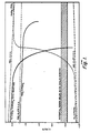
- Figure 1 is a graph of the open circuit voltage (OCV) of a lead acid cell and of each electrode and of the potential of each electrochemical reaction;
- Figure 2 is a schematic view of a lead-acid cell;
- Figure 3 is a sectional view of a positive plate containing conductive filler taken along line 3-3 of Figure 2;
- Figure 4 is a schematic view of a positive plate containing a positive active layer in which positive active materials are dispersed in a conductive filamentary wool.
- Referring now to Figure 1, the electrode potentials referred to the standard hydrogen electrode are shown for the open circuit voltages for the cell and of each plate. Also shown are the potentials of various reactions occurring in a lead-acid battery. The potential region below which Sn02 is reduced is shown in the cross-hatched region. A schematic cell is shown in Figure 2. The cell 10 is housed in an electrolyte-
impervious container 12 forming acell compartment 14 in which is received apositive plate 16,negative plate 18 and abody 20 of aqueous sulfuric acid electrolyte. The cell can be connected in parallel or series to other cells, not shown. Thenegative plate 18 andpositive plate 16 are connected toterminals - Positive plate reversal to less than about -0.5 V vs. SCE is to be avoided to prevent reduction of the Sn02 to tin. This can be accomplished by utilizing an over-sized positive plate and placing a 5 to 10% precharge in the positive plate so that even when discharged, there is no danger of falling into the reduction zone for stannic oxide. Another means of preventing cell reversal is to place a
circuit breaker 26 in series with theplates - The
negative plate 18 is of standard construction and is formed of a high area conductive substrate such as a lead on antimony-lead alloy ladder grid on which is deposited a layer of negative active material such as sponge lead. The negative active material can be formed by reducing a paste of lead oxide or tetra-basic lead sulfate to sponge lead. - Referring now to Figure 3 the
positive plate 16 can also be formed of aconductive ladder grid 30 containing alayer 32 of lead dioxide in which is dispersed 1 to 10% by weight of conductive tin oxide in particulate form such asrandom fibers 34. The fibers form a conduction path through thelayer 32. - The tin oxide is coated onto a substrate such as glass in powder or fiber form. Glass wool can be utilized to form the continuous phase for the layer of paste. As shown in Figure 4 the positive
active layer 40 ongrid 44 comprisesglass wool 42 containing aconductive coating 46 of stannic oxide. The glass wool is impregnated with apaste 48 of lead dioxide and dried to form thelayer 40 which contains a continuous conduction path through the filamentary glass wool from theoutside surface 50 facing the electrolyte to theback surface 52 in contact with thegrid 44. The stannic oxide coated glass wool can be chopped into roving or short lengths of glass fiber, or powder can be coated with conductive stannic oxide and dispersed in thewet paste before application to the grid. - The coating of stannic oxide onto glass to form conductive coating was developed over 30 years ago and has been widely practiced to defrost windshields in aircraft and automobiles. The conductive coating is applied to heated glass fibers or powder or glass wool from a solution of stannic chloride in hydrochloric acid as disclosed in U.S. Patent No. 2,564,707, the disclosure of which is expressly incorporated herein by reference. The solution can be sprayed onto the heated fibers or the fibers can be pulled through a tank containing the solution and then heated in a furnace to a suitable high temperature such as about 700°C.
- The diameter of the glass fibers is preferably very small such as from 1 to 20 microns (¡lm). Very fine fibers are too hard to handle and large diameter fibers have too small a surface to provide adequate conductive surface. The fibers contain a conductive coating of stannic oxide from a monolayer in thickness to 10 microns (pm), usually from 0.01 micron (um) to 5 microns (jim).
Claims (9)
Applications Claiming Priority (2)
| Application Number | Priority Date | Filing Date | Title |
|---|---|---|---|
| US488199 | 1983-04-25 | ||
| US06/488,199 US4507372A (en) | 1983-04-25 | 1983-04-25 | Positive battery plate |
Publications (2)
| Publication Number | Publication Date |
|---|---|
| EP0127301A1 EP0127301A1 (en) | 1984-12-05 |
| EP0127301B1 true EP0127301B1 (en) | 1989-10-04 |
Family
ID=23938735
Family Applications (1)
| Application Number | Title | Priority Date | Filing Date |
|---|---|---|---|
| EP84302574A Expired EP0127301B1 (en) | 1983-04-25 | 1984-04-16 | Improved positive battery plate |
Country Status (4)
| Country | Link |
|---|---|
| US (1) | US4507372A (en) |
| EP (1) | EP0127301B1 (en) |
| JP (1) | JPS601758A (en) |
| DE (1) | DE3480040D1 (en) |
Families Citing this family (27)
| Publication number | Priority date | Publication date | Assignee | Title |
|---|---|---|---|---|
| JPS6132365A (en) * | 1984-07-23 | 1986-02-15 | Japan Storage Battery Co Ltd | Retainer-type lead storage battery |
| US5126218A (en) * | 1985-04-23 | 1992-06-30 | Clarke Robert L | Conductive ceramic substrate for batteries |
| US5549990A (en) * | 1986-03-24 | 1996-08-27 | Ensci Inc | Battery element containing porous particles |
| US4873161A (en) * | 1988-08-19 | 1989-10-10 | Rippel Wally E | Positive paste with lead-coated glass fibers |
| US5334464A (en) * | 1991-07-22 | 1994-08-02 | Bipolar Power Corporation | Lightweight battery plates |
| US5643696A (en) * | 1991-07-22 | 1997-07-01 | Bipolar Power Corporation | Battery plates with lightweight cores |
| US5667917A (en) * | 1991-09-10 | 1997-09-16 | Idaho Research Foundation | Electrode with conductive fillers |
| US5645959A (en) * | 1992-08-20 | 1997-07-08 | Bipolar Power Corporation | Battery plates with self-passivating iron cores and mixed acid electrolyte |
| US5368960A (en) * | 1993-07-23 | 1994-11-29 | Rowlette; John J. | Utilization efficiencies by using high sulfate starting materials |
| CA2386764A1 (en) * | 1999-10-06 | 2001-04-12 | Kvg Technologies, Inc. | Battery paste |
| US6531248B1 (en) | 1999-10-06 | 2003-03-11 | Squannacook Technologies Llc | Battery paste |
| US6929858B2 (en) * | 2002-03-25 | 2005-08-16 | Squannacook Technologies Llc | Glass fibers |
| US7159805B2 (en) * | 2002-03-25 | 2007-01-09 | Evanite Fiber Corporation | Methods of modifying fibers |
| BRPI0415854B1 (en) * | 2003-10-21 | 2014-11-18 | Johnson Controls Tech Co | Method for Producing a Lead Acid Battery Plate and Method for Producing a Lead Acid Battery |
| US7118830B1 (en) * | 2004-03-23 | 2006-10-10 | Hammond Group, Inc. | Battery paste additive and method for producing battery plates |
| US8021784B2 (en) * | 2004-03-23 | 2011-09-20 | Hammond Group, Inc. | Cureless battery paste and method for producing battery plates |
| AR064292A1 (en) * | 2006-12-12 | 2009-03-25 | Commw Scient Ind Res Org | ENHANCED ENERGY STORAGE DEVICE |
| AR067238A1 (en) * | 2007-03-20 | 2009-10-07 | Commw Scient Ind Res Org | OPTIMIZED DEVICES FOR ENERGY STORAGE |
| US8404382B2 (en) | 2008-04-08 | 2013-03-26 | Trojan Battery Company | Flooded lead-acid battery and method of making the same |
| KR20120027260A (en) | 2009-04-23 | 2012-03-21 | 후루카와 덴치 가부시키가이샤 | Process for producing negative plate for lead storage battery, and lead storage battery |
| JP5711483B2 (en) | 2009-08-27 | 2015-04-30 | 古河電池株式会社 | Method for producing negative electrode plate of composite capacitor for lead storage battery and lead storage battery |
| AU2010292966B2 (en) | 2009-08-27 | 2014-07-24 | Commonwealth Scientific And Industrial Research Organisation | Electrical storage device and electrode thereof |
| JP5797384B2 (en) | 2009-08-27 | 2015-10-21 | 古河電池株式会社 | Composite capacitor negative electrode plate for lead acid battery and lead acid battery |
| JP2012133959A (en) | 2010-12-21 | 2012-07-12 | Furukawa Battery Co Ltd:The | Composite capacitor negative electrode plate for lead storage battery, and lead storage battery |
| CN105406063A (en) * | 2015-12-31 | 2016-03-16 | 天能集团江苏科技有限公司 | Lead-carbon battery positive electrode lead plaster added with electroconductive glass fiber |
| US10319990B2 (en) | 2016-08-05 | 2019-06-11 | Trojan Battery Ireland Ltd. | Coated lead acid battery electrode plates; method for making coated electrode plates and lead acid batteries containing coated electrode plates |
| CN111509220B (en) * | 2020-04-27 | 2021-11-09 | 天能电池集团股份有限公司 | Lead paste formula for positive plate of lead storage battery |
Family Cites Families (14)
| Publication number | Priority date | Publication date | Assignee | Title |
|---|---|---|---|---|
| GB189322674A (en) * | 1893-11-25 | 1894-11-24 | Reginald Haddan | Improvements in or relating to Electric Regenerative Batteries or Accumulators, and in Porous Cells therefor. |
| US1788571A (en) * | 1927-02-02 | 1931-01-13 | Vulcanite Inc | Active material for storage batteries |
| US2107937A (en) * | 1935-05-29 | 1938-02-08 | Electric Storage Battery Co | Method of making storage battery plates |
| US2564707A (en) * | 1947-09-03 | 1951-08-21 | Corning Glass Works | Electrically conducting coatings on glass and other ceramic bodies |
| GB1207989A (en) * | 1967-07-19 | 1970-10-07 | Ici Ltd | Grids for the plates of secondary cells and batteries |
| US4143212A (en) * | 1976-10-18 | 1979-03-06 | Tokyo Shibaura Electric Co., Ltd. | Sealed storage battery |
| DE2724839A1 (en) * | 1977-06-02 | 1978-12-14 | Varta Batterie | ELECTRODE PLATE FOR LEAD ACCUMULATORS |
| JPS5450839A (en) * | 1977-09-28 | 1979-04-21 | Japan Storage Battery Co Ltd | Lead storage battery |
| JPS5450833A (en) * | 1977-09-29 | 1979-04-21 | Suwa Seikosha Kk | Button type battery |
| US4329408A (en) * | 1980-06-02 | 1982-05-11 | Gould Inc. | Lead oxide composition for use in lead-acid batteries |
| US4323470A (en) * | 1980-08-25 | 1982-04-06 | Globe-Union Inc. | Battery paste for lead-acid storage batteries |
| DE3038456A1 (en) * | 1980-10-11 | 1982-06-03 | Robert Bosch Gmbh, 7000 Stuttgart | Electrode for lead accumulator - where active mass is reinforced by highly oriented carbon fibres so charging time of accumulator is reduced |
| US4326017A (en) * | 1981-01-26 | 1982-04-20 | General Electric Company | Positive electrode for lead acid battery |
| JPS5835867A (en) * | 1981-08-26 | 1983-03-02 | Yuasa Battery Co Ltd | Pasted lead storage battery |
-
1983
- 1983-04-25 US US06/488,199 patent/US4507372A/en not_active Expired - Lifetime
-
1984
- 1984-04-16 DE DE8484302574T patent/DE3480040D1/en not_active Expired
- 1984-04-16 EP EP84302574A patent/EP0127301B1/en not_active Expired
- 1984-04-25 JP JP59083603A patent/JPS601758A/en active Pending
Also Published As
| Publication number | Publication date |
|---|---|
| US4507372A (en) | 1985-03-26 |
| DE3480040D1 (en) | 1989-11-09 |
| JPS601758A (en) | 1985-01-07 |
| EP0127301A1 (en) | 1984-12-05 |
Similar Documents
| Publication | Publication Date | Title |
|---|---|---|
| EP0127301B1 (en) | Improved positive battery plate | |
| US4510219A (en) | Battery plate containing filler with conductive coating | |
| US9263745B2 (en) | Rechargeable electrochemical battery cell | |
| CA1235737A (en) | Unitary plate electrode | |
| US6117196A (en) | Method of manufacturing a lead acid cell paste and battery | |
| US4735870A (en) | Lead-acid battery construction | |
| JP2003051306A (en) | Negative electrode for lead-acid battery | |
| US5667917A (en) | Electrode with conductive fillers | |
| US4625395A (en) | Battery plate containing filler with conductive coating | |
| US10381683B2 (en) | Metal plating-based electrical energy storage cell | |
| EP1261049B1 (en) | Electrode grid for lead acid batteries coated with a conductive polymeric matrix and method of manufacture | |
| US4140589A (en) | Method for lead crystal storage cells and storage devices made therefrom | |
| US4873161A (en) | Positive paste with lead-coated glass fibers | |
| Rowlette | Lead-acid battery construction | |
| CA1323397C (en) | Lead accumulators | |
| Rowlette | Positive battery plate | |
| JPH0837001A (en) | Positive electrode plate for lead-acid battery and manufacture of the electrode plate | |
| JP2808685B2 (en) | Lead storage battery | |
| Rippel et al. | Positive paste with lead-coated glass fibers | |
| WO2000046868A1 (en) | Lead-tin alloy current collectors, batteries made thereof and methods for manufacturing same | |
| De Marco | Influence of lead (II) carbonate films of non-antimonial grids on the deep discharge cycling behaviour of maintenance-free lead/acid batteries | |
| GB2238159A (en) | Lead accumulator | |
| JPH06267524A (en) | Sealed lead-acid battery | |
| JPH09147844A (en) | Sealed lead-acid battery | |
| JPH04109558A (en) | Positive electrode plate for lead storage battery and manufacture thereof |
Legal Events
| Date | Code | Title | Description |
|---|---|---|---|
| PUAI | Public reference made under article 153(3) epc to a published international application that has entered the european phase |
Free format text: ORIGINAL CODE: 0009012 |
|
| AK | Designated contracting states |
Designated state(s): BE DE FR GB IT |
|
| 17P | Request for examination filed |
Effective date: 19850528 |
|
| 17Q | First examination report despatched |
Effective date: 19860204 |
|
| D17Q | First examination report despatched (deleted) | ||
| ITF | It: translation for a ep patent filed |
Owner name: BARZANO' E ZANARDO ROMA S.P.A. |
|
| GRAA | (expected) grant |
Free format text: ORIGINAL CODE: 0009210 |
|
| AK | Designated contracting states |
Kind code of ref document: B1 Designated state(s): BE DE FR GB IT |
|
| ET | Fr: translation filed | ||
| REF | Corresponds to: |
Ref document number: 3480040 Country of ref document: DE Date of ref document: 19891109 |
|
| PG25 | Lapsed in a contracting state [announced via postgrant information from national office to epo] |
Ref country code: BE Effective date: 19900430 |
|
| PLBE | No opposition filed within time limit |
Free format text: ORIGINAL CODE: 0009261 |
|
| STAA | Information on the status of an ep patent application or granted ep patent |
Free format text: STATUS: NO OPPOSITION FILED WITHIN TIME LIMIT |
|
| 26N | No opposition filed | ||
| BERE | Be: lapsed |
Owner name: CALIFORNIA INSTITUTE OF TECHNOLOGY Effective date: 19900430 |
|
| ITTA | It: last paid annual fee | ||
| PGFP | Annual fee paid to national office [announced via postgrant information from national office to epo] |
Ref country code: GB Payment date: 19990317 Year of fee payment: 16 Ref country code: FR Payment date: 19990317 Year of fee payment: 16 |
|
| PGFP | Annual fee paid to national office [announced via postgrant information from national office to epo] |
Ref country code: DE Payment date: 19990429 Year of fee payment: 16 |
|
| PG25 | Lapsed in a contracting state [announced via postgrant information from national office to epo] |
Ref country code: GB Free format text: LAPSE BECAUSE OF NON-PAYMENT OF DUE FEES Effective date: 20000416 |
|
| GBPC | Gb: european patent ceased through non-payment of renewal fee |
Effective date: 20000416 |
|
| PG25 | Lapsed in a contracting state [announced via postgrant information from national office to epo] |
Ref country code: FR Free format text: LAPSE BECAUSE OF NON-PAYMENT OF DUE FEES Effective date: 20001229 |
|
| PG25 | Lapsed in a contracting state [announced via postgrant information from national office to epo] |
Ref country code: DE Free format text: LAPSE BECAUSE OF NON-PAYMENT OF DUE FEES Effective date: 20010201 |
|
| REG | Reference to a national code |
Ref country code: FR Ref legal event code: ST |