EP0127218B1 - A device for the ejection of boxes through the exit of a container and a box adapted for use in such a device - Google Patents
A device for the ejection of boxes through the exit of a container and a box adapted for use in such a device Download PDFInfo
- Publication number
- EP0127218B1 EP0127218B1 EP84200604A EP84200604A EP0127218B1 EP 0127218 B1 EP0127218 B1 EP 0127218B1 EP 84200604 A EP84200604 A EP 84200604A EP 84200604 A EP84200604 A EP 84200604A EP 0127218 B1 EP0127218 B1 EP 0127218B1
- Authority
- EP
- European Patent Office
- Prior art keywords
- boxes
- box
- rotating gear
- stack
- container
- Prior art date
- Legal status (The legal status is an assumption and is not a legal conclusion. Google has not performed a legal analysis and makes no representation as to the accuracy of the status listed.)
- Expired
Links
- 230000007246 mechanism Effects 0.000 claims description 11
- 238000000926 separation method Methods 0.000 description 5
- 230000007723 transport mechanism Effects 0.000 description 3
- 230000008878 coupling Effects 0.000 description 2
- 238000010168 coupling process Methods 0.000 description 2
- 238000005859 coupling reaction Methods 0.000 description 2
- 230000005484 gravity Effects 0.000 description 2
- 230000003213 activating effect Effects 0.000 description 1
- 230000015572 biosynthetic process Effects 0.000 description 1
- 230000006835 compression Effects 0.000 description 1
- 238000007906 compression Methods 0.000 description 1
- 238000010276 construction Methods 0.000 description 1
- 239000011888 foil Substances 0.000 description 1
- 238000005755 formation reaction Methods 0.000 description 1
- 239000003365 glass fiber Substances 0.000 description 1
- 230000000266 injurious effect Effects 0.000 description 1
Images

Classifications
-
- B—PERFORMING OPERATIONS; TRANSPORTING
- B65—CONVEYING; PACKING; STORING; HANDLING THIN OR FILAMENTARY MATERIAL
- B65G—TRANSPORT OR STORAGE DEVICES, e.g. CONVEYORS FOR LOADING OR TIPPING, SHOP CONVEYOR SYSTEMS OR PNEUMATIC TUBE CONVEYORS
- B65G59/00—De-stacking of articles
- B65G59/10—De-stacking nested articles
- B65G59/107—De-stacking nested articles by means of rotary devices or endless elements
-
- B—PERFORMING OPERATIONS; TRANSPORTING
- B64—AIRCRAFT; AVIATION; COSMONAUTICS
- B64D—EQUIPMENT FOR FITTING IN OR TO AIRCRAFT; FLIGHT SUITS; PARACHUTES; ARRANGEMENT OR MOUNTING OF POWER PLANTS OR PROPULSION TRANSMISSIONS IN AIRCRAFT
- B64D1/00—Dropping, ejecting, releasing or receiving articles, liquids, or the like, in flight
- B64D1/02—Dropping, ejecting, or releasing articles
-
- F—MECHANICAL ENGINEERING; LIGHTING; HEATING; WEAPONS; BLASTING
- F41—WEAPONS
- F41H—ARMOUR; ARMOURED TURRETS; ARMOURED OR ARMED VEHICLES; MEANS OF ATTACK OR DEFENCE, e.g. CAMOUFLAGE, IN GENERAL
- F41H11/00—Defence installations; Defence devices
- F41H11/02—Anti-aircraft or anti-guided missile or anti-torpedo defence installations or systems
-
- F—MECHANICAL ENGINEERING; LIGHTING; HEATING; WEAPONS; BLASTING
- F41—WEAPONS
- F41J—TARGETS; TARGET RANGES; BULLET CATCHERS
- F41J2/00—Reflecting targets, e.g. radar-reflector targets; Active targets transmitting electromagnetic or acoustic waves
-
- F—MECHANICAL ENGINEERING; LIGHTING; HEATING; WEAPONS; BLASTING
- F42—AMMUNITION; BLASTING
- F42B—EXPLOSIVE CHARGES, e.g. FOR BLASTING, FIREWORKS, AMMUNITION
- F42B12/00—Projectiles, missiles or mines characterised by the warhead, the intended effect, or the material
- F42B12/02—Projectiles, missiles or mines characterised by the warhead, the intended effect, or the material characterised by the warhead or the intended effect
- F42B12/36—Projectiles, missiles or mines characterised by the warhead, the intended effect, or the material characterised by the warhead or the intended effect for dispensing materials; for producing chemical or physical reaction; for signalling ; for transmitting information
- F42B12/56—Projectiles, missiles or mines characterised by the warhead, the intended effect, or the material characterised by the warhead or the intended effect for dispensing materials; for producing chemical or physical reaction; for signalling ; for transmitting information for dispensing discrete solid bodies
- F42B12/70—Projectiles, missiles or mines characterised by the warhead, the intended effect, or the material characterised by the warhead or the intended effect for dispensing materials; for producing chemical or physical reaction; for signalling ; for transmitting information for dispensing discrete solid bodies for dispensing radar chaff or infrared material
Definitions
- the invention relates to a device for separating boxes from a stack of boxes which is arranged to be slidable along a guiding member, said device being provided with a retaining and transporting mechanism comprising rotating gear means which cooperate with translating gear engaging means on each of said boxes.
- the rotating gear means of the retaining and translating mechanism comprise two circumferentially offset flange-shaped circular box supporting sections of which one section separates an end box from a stack of boxes whilst the other section retains the remaining boxes of the stack.
- the boxes are kept together in the stack by gravity forces and friction forces.
- the stack In order to remove a separated end box the stack must stay in a vertical position. Ejection of the end box with a starting velocity which considerably differs from zero velocity is not envisaged in the known device and would lead to a different structure as is shown.
- said guiding member is a container wherein the stack of boxes is slidable in a direction perpendicular to the rotation axis of said rotating gear means, said boxes being coupled to each other by flexible snap-connection means on each box during transport up to said rotating gear means, said rotating gear means uncoupling an end box at one end of the stack from the adjacent box in the stack by releasing the respective flexible snap-connection means and subsequently ejecting the uncoupled box through an exit located adjacent to said rotating gear means of the container, whilst keeping the remaining boxes connected to each other by cooperating with said gear engaging means.
- an apparatus for dispensing food receptacles is known from GB-A-1.079.167.
- a relatively complicated reciprocating disassembling member and a separate hold-down member are used to separate and remove an end receptacle.
- the receptacles in a stack may be coupled by bands which are snapped into or onto cooperating formations on . the receptacle.
- a further object of the invention is to provide a device with a relatively simple shape of the rotating gear means.
- Such a device is characterized in that said rotating gear means is provided with a tooth of which a leading part ejects said uncoupled end box whilst a tailing part of the same tooth simultaneously retains the stack of said remaining coupled boxes.
- An additional object of the invention is to provide a device wherein the boxes are protected against damage during transport in the container.
- Said object of the invention is accomplished in that said retaining and transporting mechanism comprises a piston which is slidable in said container and which is provided with a first and a second plate of which said first leading plate is biased against the stack of boxes by means of a spring arranged between said first leading plate and said second tailing plate.
- Still a further object of the invention is to provide a device with a relatively simple drive mechanism for both the rotating gear means and the piston.
- This object of the invention is obtained in that said rotating gear means is rotated and said second tailing plate of the displacer is translated by one and the same cable drive mechanism, the circumferential velocity of said rotating gear means at the location of cooperation with said translating gear engaging means of said end box being equal to the translation velocity of said tailing plate of the piston.
- a box according to the prior art portion of Claim 1 is known from DE-A-1.902.941.
- Still a further object of the invention is to provide a box with a particular shape which is adapted to the first gear means of the transport mechanism.
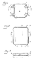
- Fig. 1 shows a frontview of the ejection device
- Fig. 2 shows a longitudinal cross-section of the ejection device along the line II-II in Fig. 1
- Fig. 3 shows a box adapted to the ejection device according to Figures 1 and 2
- Fig. 4 shows a cross-section through the box according to Fig. 3 along the line IV-IV
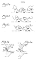
- Fig. 5a-c show cooperation between first and second gear means in different positions during the separation and ejection phase
- Fig. 6a-b show the snapping means connection two adjacent boxes
- Fig. 6a showing the situation before separation of adjacent boxes corresponding to Fig. 5a and Fig. 6b showing the situation during separation of adjacent boxes according to figures 5b and 5c.
- an ejection device 1 for dispensing chaff which comprises a container 2 for chaff boxes 30 and a drive mechanism 4-22 for driving a train of boxes to an exit 3 of the container 2 and for the separation and feeding out of boxes 30 at the exit 3.
- a driving motor (not shown) drives a first shaft 4 on which a belt pulley 5 and a gear wheel 6 are fixedly arranged.
- the gear wheel 6 cooperates with a similar gear wheel 7 which together with a belt pulley 8 is fixedly arranged on a second shaft 9 arranged parallel to the first shaft 4.
- the shafts 4 and 9 are arranged adjacent to the end of the container situated farest away from the exit 3 of the container. Adjacent to exit 3 the first gear means 12 and 12' are arranged opposite to each other. Both gear means 12 and 12' comprise a pair of gearwheels 13,14 and 13', 14' respectively (fig. 1), each pair being rigidly arranged on parallel common shafts 15 and 15' respectively. Eventually, the gear wheels 13, 14 and the common shaft 15 may be formed as one piece as well as the gear wheels 13', 14' and the common shaft 15'.
- Driving belts 10 and 11 respectively connect the two gear units 12 and 12'. The ends of the driving belts 10 and 11 are attached to a compressible piston 16 which is slidably arranged in the container 2.
- the piston 16 comprises two parallel plates 19 and 20 with a spring 21 therebetween.
- the ends of the belts 10 and 11 are fixed to the plate 20 situated farest away from the exit 3 of the container 2.
- the front plate 19 may be provided with recesses 22 in order to admit the passage of the driving belts 10 and 11.
- the position of two chaff boxes 30 has been indicated with dash-dotted lines. In reality, however, the complete container space betwen the piston 16 and the exit 3 is filled up with chaff boxes 30.
- Figures 3 and 4 show a chaff box 30 adapted to the described transport mechanism.
- the box 30 is limited by a bottom plate 31 and side walls 32.
- Side walls 32 are constituted by two oppositely arranged straight parallel side walls 33 and 34 and two side walls 35 and 36 connecting said parallel side walls 33 and 34.
- the box 30 is closed by a bottom plate 31 of an adjacent box.
- the adjacent box is indicated with dash-dotted lines in Fig. 4.
- Chaffs of several lengths adapted to different frequency ranges are kept in the boxes.
- the chaffs may be of, for example, foil or glassfiber type.
- the opposite parallel side walls 33 and 34 are - provided with second gear means 37 and 38.
- the second gear means 37 and 38 consist of an oblong projecting part formed in one piece with the side walls 33 and 34.
- the projecting parts 37 and 38 are somewhat inclined.
- the described second gear means 37 and 38 may be constituted by more than one gear element. For example a separate gear element may be provided for each of the first gear means 13, 14, 13', 14' arranged adjacent to the exit 3 of the container 2.
- the side walls 32 may be tapered close to the boxes in front of and behind of it in such a way that the boxes can be pushed into each other.
- the side walls 32 may be given a somewhat conical shape in order to obtain a reliable coupling between the boxes.
- the boxes 30 are provided with flexible snapping means in order to connect adjacent boxes to each other.
- a snapping means comprises, as is most apparent from Figures 6 and 6b, a flexible projection 41 formed in the side walls 32 of a box and a recess 42 likewise formed in the side walls 32 of a box. In an assembled position a projection 41 in one box 30 engages with a recess 42 in an adjacent box 30.
- a further flexible projection 43 may be arranged adjacent to the projection 41. This projection 41 constitutes a point of action for activating the snapping means.
- ridges 44 may be provided on the outside of the side walls 32 (Fig. 3). These ridges cause a reduction of the friction between a train of attached boxes 30 and the walls of the container 2.
- the container 2 is filled by rotating the gear wheels 12 and 12' so that a train of attached chaff boxes 30 can be inserted in the container 2 through exit 3 and slided against the piston 16.
- the gear wheels 12 and 12' are then rotated back so that they engage with the second gear means on the box being situated closest to the container exit 3.
- the compression piston 16 biases the train of boxes in the direction towards the exit 3.
- Ejection of chaff boxes is initiated by starting a drive motor which rotates the shaft 4 supporting the belt pulley 5 and the gear wheel 6.
- the gear wheel 6 rotates the gear wheel 7 and the belt pulley 8.
- the belt pulley 5 drives the belt 10 which via the shaft 15 rotates the gear wheels 13 and 14 of first gear means 12.
- the belt pulley 8 in the same way drives the belt 11 which via a shaft 15' rotates the gear wheels 13' and 14' of first gear means 12'.
- the drive mechanism may be supplemented with guide rollers.
- guide rollers which serve to guide the belts towards the outer walls of the container may be arranged on the outside of the container close to the first gear means.
- the gear wheels 13, 14, 13', 14' engage with the corresponding second gear means 37, 38 of the chaff boxes and ensure that the boxes 30 are ejected one by one.
- the compressible piston 16 exerts a force on the train of boxes in the direction towards the container exit and ensures by means of its compressibility that the boxes, the gear means 12, 12', the belts 10, 11 and even the further parts of the drive mechanism are not subjected to injurious forces.
- Fig. 5a shows a position in which a tooth 52 of a gear wheel 13, 14, 13', 14' just has entered into the space between the gear means 37b and 37c, while the tooth 51 on one hand gives the box 30a situated closest to the exit 3 a final push out of the container 2 and on the other hand prevents the box 30b from leaving the container 2.
- the chaff boxes 30b and 30c are moved closer to the exit and the tooth 52 opens the snapping means by pressing aside a projection 43.
- the snapping means are shown in more detail in Figures 6a and 6b, Fig. 6b showing a position which corresponds to that of Fig. 5b.
- the tooth 52 tends to increase the distance between the gear means 37b and 37c, so that the box 30b situated closest to the exit 3 starts to separate from the train of chaff boxes situated behind it.
- the tooth 53 ensures that the train of chaff boxes is moved towards the exit.
- the exit is provided with a total of four gear wheels 13, 14, 13', 14'.
- gear wheels 13, 14, 13', 14' it is possible to increase or decrease the number of gear wheels.
- solutions with only one or two gear wheels are possible.
- the driving of the gear wheels 13, 14, 13', 14' at the exit 3 of the container may be performed step by step or continuously during a limited period of time.
- driving belts are used for driving of the gear wheels at the exit 3 of the container. These belts may be perforated and cooperate with belt pulleys provided with teeth. Alternatively, the belt driving may be replaced by a wire-or chain driving.
- the piston is omitted and the gear wheels 13, 13' serve as well for the transport as for the ejection.
- the driving motor may be located in direct connection with the gear means 12, 12' which may be coupled via further gear wheels.
- the described principle for ejection of boxes from a container may be used also in devices other than chaff ejection devices.
- the principle may be used for example in vending machines for food articles or assembly lines for sequentially feeding out products from the line.
Landscapes
- Engineering & Computer Science (AREA)
- General Engineering & Computer Science (AREA)
- Radar, Positioning & Navigation (AREA)
- Remote Sensing (AREA)
- Aviation & Aerospace Engineering (AREA)
- Physics & Mathematics (AREA)
- Combustion & Propulsion (AREA)
- Electromagnetism (AREA)
- Chemical & Material Sciences (AREA)
- Control And Other Processes For Unpacking Of Materials (AREA)
- De-Stacking Of Articles (AREA)
- Apparatus For Making Beverages (AREA)
- Filling Or Emptying Of Bunkers, Hoppers, And Tanks (AREA)
Applications Claiming Priority (2)
| Application Number | Priority Date | Filing Date | Title |
|---|---|---|---|
| SE8302508 | 1983-05-03 | ||
| SE8302508A SE435964B (sv) | 1983-05-03 | 1983-05-03 | Kugghjulsforsedd utmatningsanordning samt behallare for radarstorremsor och liknande |
Publications (2)
| Publication Number | Publication Date |
|---|---|
| EP0127218A1 EP0127218A1 (en) | 1984-12-05 |
| EP0127218B1 true EP0127218B1 (en) | 1987-09-02 |
Family
ID=20351051
Family Applications (1)
| Application Number | Title | Priority Date | Filing Date |
|---|---|---|---|
| EP84200604A Expired EP0127218B1 (en) | 1983-05-03 | 1984-05-02 | A device for the ejection of boxes through the exit of a container and a box adapted for use in such a device |
Country Status (7)
| Country | Link |
|---|---|
| US (2) | US4650092A (OSRAM) |
| EP (1) | EP0127218B1 (OSRAM) |
| JP (1) | JPS602529A (OSRAM) |
| CA (1) | CA1236436A (OSRAM) |
| DE (1) | DE3465693D1 (OSRAM) |
| IL (1) | IL71705A (OSRAM) |
| SE (1) | SE435964B (OSRAM) |
Families Citing this family (16)
| Publication number | Priority date | Publication date | Assignee | Title |
|---|---|---|---|---|
| SE435964B (sv) * | 1983-05-03 | 1984-10-29 | Philips Norden Ab | Kugghjulsforsedd utmatningsanordning samt behallare for radarstorremsor och liknande |
| SE456901B (sv) * | 1987-02-09 | 1988-11-14 | Philips Norden Ab | Behaallare foer stoermedel |
| SE505070C2 (sv) * | 1991-03-27 | 1997-06-23 | Celsiustech Electronics Ab | Behållare för störmedel |
| SE501881C2 (sv) * | 1991-04-29 | 1995-06-12 | Celsiustech Electronics Ab | Fällare för utmatning av förpackningar med störmedel |
| SE517872C2 (sv) * | 1998-12-02 | 2002-07-30 | Saab Ab | Flygburen fällare för spridning av störmedel |
| US7066708B1 (en) * | 1999-10-19 | 2006-06-27 | Micron Technology, Inc. | Methods and apparatus for retaining a tray stack having a plurality of trays for carrying microelectric devices |
| GB2358183A (en) * | 2000-01-14 | 2001-07-18 | Hughes Whitlock Ltd | Light photon detecting apparatus and a filter and/or collection system therefor |
| SE520197C2 (sv) | 2001-05-07 | 2003-06-10 | Saab Ab | Förfarande för utmatning av IR-och radarmotmedel och/eller laserreflektorer ur en därför avsedd fällare, samt för utmatning av dylika motmedel eller reflektorer avsedd fällare |
| SE523215C2 (sv) * | 2001-05-07 | 2004-04-06 | Saab Ab | Förfarande för utmatning av motmedel, fällaranordning samt raketkastare |
| SE525519C2 (sv) * | 2003-02-10 | 2005-03-01 | Saab Ab | Förfarande för att framställa värmegenerande motmedel, samt förpackning med värmegenerande motmedel |
| EP1696510A1 (en) * | 2005-02-23 | 2006-08-30 | Saab Ab | Deployable radar reflector |
| DE602007009262D1 (de) * | 2007-10-30 | 2010-10-28 | Saab Ab | Spendersystem für die Ausgabe von Gegenmitteln |
| EP2382439B1 (en) | 2009-01-16 | 2015-08-19 | Saab AB | Cassette arranged for accommodating a pay load of pyrophoric material |
| US8132492B1 (en) * | 2009-02-09 | 2012-03-13 | Meggitt Defense Systems | Dispensing device for infrared special material |
| WO2017200457A1 (en) * | 2016-05-17 | 2017-11-23 | Saab Ab | Dispenser with a cover and method for launching countermeasures |
| IL293425B2 (en) | 2019-12-05 | 2025-04-01 | Saab Ab | Ammunition box ejection system |
Family Cites Families (9)
| Publication number | Priority date | Publication date | Assignee | Title |
|---|---|---|---|---|
| US3424334A (en) * | 1964-10-09 | 1969-01-28 | Joseph Goltz | Stacking box construction with interlock |
| GB1079167A (en) * | 1965-06-10 | 1967-08-16 | Cease Central Inc | Apparatus for dispensing food receptacles |
| GB1111015A (en) * | 1966-07-07 | 1968-04-24 | Coroga Co | Cup dispenser |
| US3391827A (en) * | 1967-02-15 | 1968-07-09 | Bextic Inc | Dispensing articles from a stack by fluid pressures |
| US3455484A (en) * | 1967-09-08 | 1969-07-15 | Illinois Tool Works | Container dispensing apparatus |
| DE1902941A1 (de) * | 1969-01-22 | 1970-08-27 | Lehner Stirnemann Max | Geraet zur vereinzelten Abgabe gestapelter,einen Rand aufweisender Schalen |
| FR2123054B1 (OSRAM) * | 1970-09-08 | 1974-04-26 | Gournelle Maurice | |
| JPS5240492U (OSRAM) * | 1975-09-16 | 1977-03-23 | ||
| SE435964B (sv) * | 1983-05-03 | 1984-10-29 | Philips Norden Ab | Kugghjulsforsedd utmatningsanordning samt behallare for radarstorremsor och liknande |
-
1983
- 1983-05-03 SE SE8302508A patent/SE435964B/sv not_active IP Right Cessation
-
1984
- 1984-04-26 US US06/604,279 patent/US4650092A/en not_active Expired - Lifetime
- 1984-04-26 CA CA000452816A patent/CA1236436A/en not_active Expired
- 1984-04-28 JP JP59085199A patent/JPS602529A/ja active Granted
- 1984-04-30 IL IL71705A patent/IL71705A/xx not_active IP Right Cessation
- 1984-05-02 EP EP84200604A patent/EP0127218B1/en not_active Expired
- 1984-05-02 DE DE8484200604T patent/DE3465693D1/de not_active Expired
-
1987
- 1987-09-03 US US07/094,048 patent/US5018249A/en not_active Expired - Fee Related
Also Published As
| Publication number | Publication date |
|---|---|
| CA1236436A (en) | 1988-05-10 |
| IL71705A0 (en) | 1984-07-31 |
| US4650092A (en) | 1987-03-17 |
| JPH0520329B2 (OSRAM) | 1993-03-19 |
| JPS602529A (ja) | 1985-01-08 |
| EP0127218A1 (en) | 1984-12-05 |
| US5018249A (en) | 1991-05-28 |
| IL71705A (en) | 1987-10-30 |
| SE435964B (sv) | 1984-10-29 |
| SE8302508D0 (sv) | 1983-05-03 |
| DE3465693D1 (en) | 1987-10-08 |
Similar Documents
| Publication | Publication Date | Title |
|---|---|---|
| EP0127218A1 (en) | A device for the ejection of boxes through the exit of a container and a box adapted for use in such a device | |
| US9670007B2 (en) | Accumulating device | |
| DE69728646T2 (de) | Maschine zum ordnungsgemässen zuführen von flaschen | |
| WO1991004211A1 (de) | Modulare fördereinrichtung | |
| US4261259A (en) | Beverage container crusher | |
| US20070278240A1 (en) | Apparatus for Dispensing of Stacked Objects, a Method for Dispensing Stacked Objects and a System Comprising an Apparatus for Dispensing | |
| EP1428758B1 (de) | Vorrichtung zum Sortieren und zum Weitertransport von Schüttgut | |
| US4511300A (en) | Apparatus for gathering writing pads or the like | |
| WO2011158145A1 (de) | Vorrichtung zum aufbringen von kabeltüllen auf ein kabel | |
| EP0509583A1 (en) | Buffer apparatus and driving system | |
| US5048574A (en) | System for the storage and separation of bobbin formers | |
| US6808061B2 (en) | Process and apparatus for depositing products in a defined manner from a compartment-containing chain | |
| KR20010014243A (ko) | 컨베이어 장치 | |
| DE1761019A1 (de) | Anlage zur Beschickung einer Verpackungsmaschine od.dgl.mit von einer Vielzahl von Packmaschinen abgegebenen Paeckchen,insbesondere Zigarettenpaeckchen | |
| DE2558288A1 (de) | Anlage fuer die herstellung von zigarettenpackungen mit direkter beschickung der zigaretten von der bzw. den herstellungsmaschinen zum trichter fuer die gruppierung und die abgabe von zigaretten an die verpackungslinie der verpackungsmaschine, sowie vorrichtung mit magazin fuer den ausgleich von produktionsschwankungen zwischen diesen maschinen | |
| CH673818A5 (OSRAM) | ||
| US20220194712A1 (en) | Modular slat conveyor belt | |
| DE3504768A1 (de) | Vorrichtung zum entfernen der umreifung von pressgut enthaltenden gebinden | |
| US5975838A (en) | Device for destacking and conveying sticks in an apparatus for inserting sticks in ice-cream bodies | |
| US7121459B2 (en) | Device for transporting banknotes in a cash dispenser | |
| DE3231961A1 (de) | Regeleinrichtung fuer das betreiben von mehrstellenantrieben in gurtbandfoerderern | |
| EP0532978A1 (de) | Kastenausstossvorrichtung | |
| KR200202654Y1 (ko) | 카드 디스펜서 | |
| SU1468713A1 (ru) | Устройство дл дроблени стружки | |
| JP7734996B2 (ja) | 気泡緩衝材減容装置 |
Legal Events
| Date | Code | Title | Description |
|---|---|---|---|
| PUAI | Public reference made under article 153(3) epc to a published international application that has entered the european phase |
Free format text: ORIGINAL CODE: 0009012 |
|
| AK | Designated contracting states |
Designated state(s): DE FR GB IT SE |
|
| RAP1 | Party data changed (applicant data changed or rights of an application transferred) |
Owner name: N.V. PHILIPS' GLOEILAMPENFABRIEKEN Owner name: PHILIPS NORDEN AB |
|
| 17P | Request for examination filed |
Effective date: 19850318 |
|
| GRAA | (expected) grant |
Free format text: ORIGINAL CODE: 0009210 |
|
| AK | Designated contracting states |
Kind code of ref document: B1 Designated state(s): DE FR GB IT SE |
|
| REF | Corresponds to: |
Ref document number: 3465693 Country of ref document: DE Date of ref document: 19871008 |
|
| ITF | It: translation for a ep patent filed | ||
| ET | Fr: translation filed | ||
| PG25 | Lapsed in a contracting state [announced via postgrant information from national office to epo] |
Ref country code: SE Effective date: 19880503 |
|
| PLBE | No opposition filed within time limit |
Free format text: ORIGINAL CODE: 0009261 |
|
| STAA | Information on the status of an ep patent application or granted ep patent |
Free format text: STATUS: NO OPPOSITION FILED WITHIN TIME LIMIT |
|
| 26N | No opposition filed | ||
| REG | Reference to a national code |
Ref country code: GB Ref legal event code: 775A |
|
| ITTA | It: last paid annual fee | ||
| REG | Reference to a national code |
Ref country code: GB Ref legal event code: 732 |
|
| EUG | Se: european patent has lapsed |
Ref document number: 84200604.1 Effective date: 19890518 |
|
| REG | Reference to a national code |
Ref country code: GB Ref legal event code: SP |
|
| REG | Reference to a national code |
Ref country code: GB Ref legal event code: IF02 |
|
| PGFP | Annual fee paid to national office [announced via postgrant information from national office to epo] |
Ref country code: GB Payment date: 20030430 Year of fee payment: 20 |
|
| PGFP | Annual fee paid to national office [announced via postgrant information from national office to epo] |
Ref country code: FR Payment date: 20030508 Year of fee payment: 20 |
|
| PGFP | Annual fee paid to national office [announced via postgrant information from national office to epo] |
Ref country code: DE Payment date: 20030515 Year of fee payment: 20 |
|
| PG25 | Lapsed in a contracting state [announced via postgrant information from national office to epo] |
Ref country code: GB Free format text: LAPSE BECAUSE OF EXPIRATION OF PROTECTION Effective date: 20040501 |
|
| REG | Reference to a national code |
Ref country code: GB Ref legal event code: PE20 |