EP0126623B2 - Gas sensor - Google Patents
Gas sensor Download PDFInfo
- Publication number
- EP0126623B2 EP0126623B2 EP84303330A EP84303330A EP0126623B2 EP 0126623 B2 EP0126623 B2 EP 0126623B2 EP 84303330 A EP84303330 A EP 84303330A EP 84303330 A EP84303330 A EP 84303330A EP 0126623 B2 EP0126623 B2 EP 0126623B2
- Authority
- EP
- European Patent Office
- Prior art keywords
- electrode
- gas
- sensor according
- electrolyte
- gas sensor
- Prior art date
- Legal status (The legal status is an assumption and is not a legal conclusion. Google has not performed a legal analysis and makes no representation as to the accuracy of the status listed.)
- Expired
Links
- 239000003792 electrolyte Substances 0.000 claims description 32
- 230000002209 hydrophobic effect Effects 0.000 claims description 23
- 238000009792 diffusion process Methods 0.000 claims description 21
- 230000002452 interceptive effect Effects 0.000 claims description 18
- 230000004888 barrier function Effects 0.000 claims description 12
- 239000000463 material Substances 0.000 claims description 8
- 239000012528 membrane Substances 0.000 claims description 7
- 239000003054 catalyst Substances 0.000 claims description 5
- 239000000126 substance Substances 0.000 claims description 5
- 238000010276 construction Methods 0.000 claims description 4
- 239000011148 porous material Substances 0.000 claims description 2
- NBVXSUQYWXRMNV-UHFFFAOYSA-N fluoromethane Chemical compound FC NBVXSUQYWXRMNV-UHFFFAOYSA-N 0.000 claims 1
- 239000007789 gas Substances 0.000 description 82
- 229910052739 hydrogen Inorganic materials 0.000 description 23
- 239000001257 hydrogen Substances 0.000 description 23
- UFHFLCQGNIYNRP-UHFFFAOYSA-N Hydrogen Chemical compound [H][H] UFHFLCQGNIYNRP-UHFFFAOYSA-N 0.000 description 22
- UGFAIRIUMAVXCW-UHFFFAOYSA-N Carbon monoxide Chemical compound [O+]#[C-] UGFAIRIUMAVXCW-UHFFFAOYSA-N 0.000 description 16
- 229910002091 carbon monoxide Inorganic materials 0.000 description 15
- 239000004810 polytetrafluoroethylene Substances 0.000 description 14
- 229920001343 polytetrafluoroethylene Polymers 0.000 description 14
- 230000000694 effects Effects 0.000 description 8
- 238000006243 chemical reaction Methods 0.000 description 6
- 238000010586 diagram Methods 0.000 description 6
- BASFCYQUMIYNBI-UHFFFAOYSA-N platinum Chemical compound [Pt] BASFCYQUMIYNBI-UHFFFAOYSA-N 0.000 description 6
- VYPSYNLAJGMNEJ-UHFFFAOYSA-N Silicium dioxide Chemical compound O=[Si]=O VYPSYNLAJGMNEJ-UHFFFAOYSA-N 0.000 description 4
- 239000011521 glass Substances 0.000 description 4
- 230000035945 sensitivity Effects 0.000 description 4
- 239000000725 suspension Substances 0.000 description 4
- IAZDPXIOMUYVGZ-UHFFFAOYSA-N Dimethylsulphoxide Chemical compound CS(C)=O IAZDPXIOMUYVGZ-UHFFFAOYSA-N 0.000 description 3
- 230000005540 biological transmission Effects 0.000 description 3
- 239000000446 fuel Substances 0.000 description 3
- 238000000034 method Methods 0.000 description 3
- 239000000203 mixture Substances 0.000 description 3
- 230000004048 modification Effects 0.000 description 3
- 238000012986 modification Methods 0.000 description 3
- 229910052697 platinum Inorganic materials 0.000 description 3
- 230000008569 process Effects 0.000 description 3
- CURLTUGMZLYLDI-UHFFFAOYSA-N Carbon dioxide Chemical compound O=C=O CURLTUGMZLYLDI-UHFFFAOYSA-N 0.000 description 2
- 238000001035 drying Methods 0.000 description 2
- 230000008030 elimination Effects 0.000 description 2
- 238000003379 elimination reaction Methods 0.000 description 2
- 238000005259 measurement Methods 0.000 description 2
- 238000012544 monitoring process Methods 0.000 description 2
- 239000000843 powder Substances 0.000 description 2
- 239000000377 silicon dioxide Substances 0.000 description 2
- 238000012360 testing method Methods 0.000 description 2
- QAOWNCQODCNURD-UHFFFAOYSA-N Sulfuric acid Chemical compound OS(O)(=O)=O QAOWNCQODCNURD-UHFFFAOYSA-N 0.000 description 1
- 230000002745 absorbent Effects 0.000 description 1
- 239000002250 absorbent Substances 0.000 description 1
- QVGXLLKOCUKJST-UHFFFAOYSA-N atomic oxygen Chemical compound [O] QVGXLLKOCUKJST-UHFFFAOYSA-N 0.000 description 1
- 229910052799 carbon Inorganic materials 0.000 description 1
- 229910002092 carbon dioxide Inorganic materials 0.000 description 1
- 239000001569 carbon dioxide Substances 0.000 description 1
- 230000003197 catalytic effect Effects 0.000 description 1
- 230000008859 change Effects 0.000 description 1
- 230000000052 comparative effect Effects 0.000 description 1
- 230000006835 compression Effects 0.000 description 1
- 238000007906 compression Methods 0.000 description 1
- 230000007423 decrease Effects 0.000 description 1
- 238000001514 detection method Methods 0.000 description 1
- 239000003546 flue gas Substances 0.000 description 1
- 239000012530 fluid Substances 0.000 description 1
- 238000004868 gas analysis Methods 0.000 description 1
- 150000002431 hydrogen Chemical class 0.000 description 1
- 238000005470 impregnation Methods 0.000 description 1
- 239000011810 insulating material Substances 0.000 description 1
- 238000004519 manufacturing process Methods 0.000 description 1
- 229910052760 oxygen Inorganic materials 0.000 description 1
- 239000001301 oxygen Substances 0.000 description 1
- 239000002245 particle Substances 0.000 description 1
- 239000002861 polymer material Substances 0.000 description 1
- 238000004886 process control Methods 0.000 description 1
- 230000004044 response Effects 0.000 description 1
- 229920006395 saturated elastomer Polymers 0.000 description 1
- 229910052717 sulfur Inorganic materials 0.000 description 1
- 239000001117 sulphuric acid Substances 0.000 description 1
- 235000011149 sulphuric acid Nutrition 0.000 description 1
- 239000002341 toxic gas Substances 0.000 description 1
Images


Classifications
-
- G—PHYSICS
- G01—MEASURING; TESTING
- G01N—INVESTIGATING OR ANALYSING MATERIALS BY DETERMINING THEIR CHEMICAL OR PHYSICAL PROPERTIES
- G01N27/00—Investigating or analysing materials by the use of electric, electrochemical, or magnetic means
- G01N27/26—Investigating or analysing materials by the use of electric, electrochemical, or magnetic means by investigating electrochemical variables; by using electrolysis or electrophoresis
- G01N27/403—Cells and electrode assemblies
- G01N27/404—Cells with anode, cathode and cell electrolyte on the same side of a permeable membrane which separates them from the sample fluid, e.g. Clark-type oxygen sensors
- G01N27/4045—Cells with anode, cathode and cell electrolyte on the same side of a permeable membrane which separates them from the sample fluid, e.g. Clark-type oxygen sensors for gases other than oxygen
-
- G—PHYSICS
- G01—MEASURING; TESTING
- G01N—INVESTIGATING OR ANALYSING MATERIALS BY DETERMINING THEIR CHEMICAL OR PHYSICAL PROPERTIES
- G01N33/00—Investigating or analysing materials by specific methods not covered by groups G01N1/00 - G01N31/00
- G01N33/0004—Gaseous mixtures, e.g. polluted air
- G01N33/0009—General constructional details of gas analysers, e.g. portable test equipment
- G01N33/0027—General constructional details of gas analysers, e.g. portable test equipment concerning the detector
- G01N33/0036—Specially adapted to detect a particular component
- G01N33/004—Specially adapted to detect a particular component for CO, CO2
-
- G—PHYSICS
- G01—MEASURING; TESTING
- G01N—INVESTIGATING OR ANALYSING MATERIALS BY DETERMINING THEIR CHEMICAL OR PHYSICAL PROPERTIES
- G01N33/00—Investigating or analysing materials by specific methods not covered by groups G01N1/00 - G01N31/00
- G01N33/0004—Gaseous mixtures, e.g. polluted air
- G01N33/0009—General constructional details of gas analysers, e.g. portable test equipment
- G01N33/0027—General constructional details of gas analysers, e.g. portable test equipment concerning the detector
- G01N33/0036—Specially adapted to detect a particular component
- G01N33/0059—Specially adapted to detect a particular component avoiding interference of a gas with the gas to be measured
Definitions
- This invention relates to electro-chemical gas sensors in which the gas or vapour to be sensed is caused to react at an electrode of an electro-chemical cell to generate a current which is a function of the concentration of the gas or vapour to be sensed.
- a problem encountered with many electro-chemical gas sensors is that they are not completely specific. In some cases an interfering gas will give a full signal at the electrode exposed to the gas, i.e. it will be fully reacted at this electrode. In other cases there is only partial reaction so that there is a residual finite partial pressure of the interfering gas at this electrode.
- EP-A-0064337 describes a sensor for sensing the presence of carbon dioxide in a fluid which may also contain oxygen as an interfering gas.
- This is a relatively complex sensor in which there is a problem in the manner in which gas reaches the electrode. From the electrode, the gas must pass by a process of diffusion in solution through a layer of aqueous electrolyte between the electrode and a membrane; secondly, again in solution, the gas must pass through a polymer material of the non-porous membrane; and thirdly in solution the gas must pass through a layer of DMSO between the membrane and the electrode.
- the gas can only reach the electrode by a process of diffusion in solution through the intervening members and this leads to a significant problem since the diffusion rate of gas in solution is relatively slow.
- US-A-3503861 also discloses a gas sensor having a series of electrodes between each pair of which is provided electrolyte held in an absorbent material. Gas passes successively through each electrode and electrolyte layer causing generation of signals relating to the concentration of the gas. Once again, gas can only have access to the electrodes by a process of diffusion of solution in the electrolyte.
- a gas sensor comprises an electro-chemical cell having a diffusion barrier controlling access of the gas to be sensed to a first electrode, an intervening body of electrolyte, a second electrode and means for measuring the current passing through each electrode, and is characterised by a gas phase path within the body of the cell, said path being permeable to gas but not to electrolyte, so enabling an interfering gas which only partially reacts at the first electrode, and hence has a finite partial pressure below the diffusion barrier and above the first electrode, to have access to the second electrode while remaining in the gas phase until it reaches the second electrode.
- the second electrode will not see any particular gas which reacts fully at the first electrode since it will be removed by this electrode first.
- the second electrode will, however, see any other gas which only partially reacts at the first electrode. For this reason it is possible to achieve partial or even complete elimination of the effect of the interfering gas as described below.
- Such a separator is used in conjunction with a hydrophobic electrode of a known fuel cell type, that is to say comprising a network of catalyst particle aggregates, which are hydrophilic and will wet up with electrolyte, interleaved with a network of porous PTFE, which is hydrophobic and will remain unwetted so providing gas paths throughout the depth of the electrode.
- a hydrophobic electrode of a known fuel cell type that is to say comprising a network of catalyst particle aggregates, which are hydrophilic and will wet up with electrolyte, interleaved with a network of porous PTFE, which is hydrophobic and will remain unwetted so providing gas paths throughout the depth of the electrode.
- Such electrodes are permeable to gas even when wetted with electrolyte.
- Such an electrode may be pressure bonded to a porous PTFE tape.
- the electrodes may be connected with a simple load resistor to enable a voltage signal, equal to iR L where i is the current and R L the value of the load resistor, to be taken off, which is a measure of the CO concentration. Hydrogen will give a partial interference signal with a normal sensor of this type.
- an additional third electrode without gas access and spaced from the second electrode within the electrolyte and means for measuring the current passing between the first electrode and the third electrode and/or the current passing between the second electrode and the third electrode, it is possible to filter out an interfering gas, i.e. an extraneous gas which interferes with the measurement of the gas of primary interest, and obtain signals corresponding to both the interfering gas and the gas of primary interest.
- the first electrode i.e. that with primary access to the gas is chosen so that, by virtue of its catalytic material and/or the potential at which it is controlled, it will fully react with the interfering gas but only partially or not at all with the gas of primary interest.
- the interfering gas fully reacts at the first electrode and does not pass on to the second electrode at all.
- the gas of primary interest wilt pass to, and react at. the second electrode so that the current between the second electrode and the third electrode which passes through the electrolyte in the usual way, provides a measure of the gas of primary interest.
- a reference electrode may be included which is connected to a potentiostatic circuit to control the potential of either the first or the second elec trode. If required, two separate potentiostatic circuits may be used to independently control the potentials of both the first and the second electrodes.
- FIG. 1 is a simple circuit diagram illustrating the principle involved in a two-electrode cell with direct gas access to sensing electrode S and gas access to a counter electrode C via the sensing electrode S.
- the space between the two electrodes is occupied by a structure indicated generally as 10 which permits the passage of both electrolyte and gas between the two electrodes.
- any gas which reacts fully at the first or sensing electrode S will be removed and will therefore not pass across the intervening space 10 to the second electrode C.
- the electrode C will respond to any other gas which reacts only partially at the first electrode S. In this way it is possible to achieve partial or even complete elimination of the effect of an interfering gas as previously described.
- the output signal of the cell is generated by passage of the cell current through a load resistor R L and appears across terminals 11, from where it can be amplified as required.
- the structure 10 between the two electrodes needs to provide both a gas diffusion path between the two electrodes and also a path for the electrolyte and Figures 2 and 3 provide theoretical diagrammatic views of these two different types of path.
- the electrodes S is shown mounted on a porous PTFE tape 4, and direct gas access to this electrode is indicated by arrows 14.
- the second electrode C is mounted on a porous PTFE tape 5 and the space between the two electrodes is occupied by a conventional hydrophilic separator 22 surrounded by a gasket 23 made of porous PTFE.
- the separator 22 is saturated with electrolyte drawn from a reservoir (not shown) by a hydrophilic wick 12 passing through a hole in the electrode C.
- Gas impinging on the surface of the tape 4 can pass through this tape into contact with the electrode S and can also spread laterally as indicated by the arrows 15, afterwhich it passes downwardly along the direction of the arrows 16 and then inwardly along the arrows 17 through the tape 5. Finally passing into contact with the electrode C along the arrows 18. It will thus be seen that a central electrolyte path through the separator 22 is surrounded by a gas path through the gasket 23.
- the separator can conveniently be made, for example, by impregnating glass filter paper with a mixed suspension of silica powder and PTFE powder, drying and curing at 300 degrees centrigrade. This will result in a separator with a network of hydrophilic channels through which electrolyte can penetrate, interleaved with a network of hydrophobic channels available for gas permeation.
- Other separator materials may, of course, be used together with other hydrophobic and hydrophilic materials, to achieve the same effect.
- An alternative method of making a partly hydrophobic, partly hydrophilic separator is to simply impregnate a glass filter paper separator in a number of restricted areas with PTFE suspension and dry and cure as before.
- the impregnated areas will be hydrophobic and provide gas channels through the separator, and the unimpregnated areas are available to provide the electrolyte connection.
- Another form of the separator is a hydrophilic separator with a hole, or holes filled with porous hydrophobic material.
- Figure 4 illustrates a modification of the basic arrangement of the first three figures, which includes an additional third electrode without gas access and spaced from the second electrode within the electrolyte.
- This third electrode becomes the counter electrode indicated as C, the first two electrodes, between which the separator 10 is located, constituting a sensing electrode S and an auxiliary electrode A respectively.
- the electrode S has the primary access to the gas under test, access to the electrode A being by way of the separator 10 as previously described.
- the potential of the electrode S is set by a bias voltage V B (S) to the value required to ensure reaction of the interfering gas at the electrode S without excessive reaction of the gas of primary interest, which passes through the electrode S to be measured at the electrode A.
- the bias voltage V B (S) is maintained constant by an operational amplifier OA1 and the current passing through the electrode S is measured by a current measuring device 20 to provide a measure of the concentration of the interfering gas.
- the current passing through the electrode A flows through a resistor R L and the voltage measured across the ends of this resistor gives the concentration of the gas of primary interest.
- Figure 5 shows a circuit similar to that of Figure 4, but including an additional reference electrode R used in conjunction with a second operational amplifier OA2 and bias voltage V B to eliminate the effect of polarisation at the cathode and to apply a bias as will be described in more detail in conjunction with Figure 8.
- the three electrodes S, A and C are hydrophobic type electrodes in which the electrode catalyst is mixed with powered PTFE and pressure bonded to porous PTFE tape 104, 105 and 106, the auxiliary electrode A and the counter electrode having holes through their middles.
- the respective current connection leads to the electrodes are shown as 107, 108 and 109.
- the partly hydrophilic, partly hydrophobic porous insulating separator is shown as 10.
- auxiliary electrode A Below the auxiliary electrode Ais a conventional hydrophilic porous insulating separator 111 and a wick 112 of similar material which contacts the electrode S through the hole in the electrode Aon PTFE tape 105 and passes through the holes in the separator 111, the counter electrode Con PTFE tape 106 and a hole 113 in a base plate 114 which provides an electrolyte reservoir 115.
- the cell may be modified to operate in accordance with a circuit shown in Figure 8 which includes an additional reference electrode and this may be included either above or below the counter electrode C.
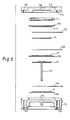
- the other components necessary for completion of the cell include a compression O-ring 116 and a top plate 117 formed with a capillary diffusion barrier 118.
- the sensor is assembled by bolting up, using bolts through holes in the base plate 114 and top plate 117, two of which holes are shown at 119.
- the reservoir 115 is partially filled with electrolyte and sealed off with a bottom cap (not shown). The electrolyte will then wick up into the various separators and electrodes.
- the separator 10 will be in close contact on the one side with the sensing electrode S and on the other side with the auxiliary electrode A so that there is a gas path through the hydrophobic channels of the sensing electrode S and the separator 10 into the auxiliary electrode A.
- diffusion barrier 118 instead of the capillary gas barrier 118, other types of diffusion barrier can be included if required, e.g. a porous membrane, a diffusion barrier having pores which are sufficiently small as to allow gas diffusion through them to be in accordance with the Knudsen principle or a non-porous membrane.
- a porous membrane e.g. a diffusion barrier having pores which are sufficiently small as to allow gas diffusion through them to be in accordance with the Knudsen principle or a non-porous membrane.
- the three electrode arrangement of Figure 4 differs from the two electrode arrangement of Figure 1 in that the second electrode which forms the counter electrode of Figure 1 becomes an auxiliary electrode in the circuit of Figure 4 and the third electrode becomes the counter electrode. Accordingly, if the three electrode cell of Figure 6 is to be used in two electrode form, the electrode A becomes the counter electrode, and the counter electrode C is omitted together with its supporting tape 106 and its current connection lead 109.
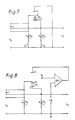
- Figure 7 is a circuit diagram illustrating the operation of the cell as shown in Figure 6 and Figure 8 is a corresponding diagram of the modified form of cell already referred to including an additional reference electrode.
- the sensing electrode S and the auxiliary electrode A are connected in parallel each in series with a respective variable resistor R s , R A , the parallel arrangement being connected in circuit with the counter electrode C. If the currents flowing through the sensing and auxiliary electrodes respectively are denoted as is and i A , it will be seen that the output signal V net from the circuit will be given by
- auxiliary electrode A As described, gas access is provided to the auxiliary electrode A via the sensing electrode S. Both the auxiliary and the sensing electrode will see a partially interfering gas so that its effect may be cancelled out.
- the two electrodes will be made as nearly identical as possible, but even so the signal from the interfering gas is liable to be lower on the auxiliary electrode than on the sensing electrode due to the longer diffusion path.
- the relative values of R A and R s may be adjusted to take account of this and so achieve substantially complete cancellation.
- the circuit of Figure 8 is similar but also includes an additional reference electrode R connected to a potential controlling operational amplifier OA3. If desired the circuit may also be use to apply a bias voltage V B . The circuit will hold the potential between the reference electrode R and ground constant at the bias voltage V B . It will be seen that the potential of the sensing electrode V s will now be given by
- the electrodes are gas diffusion electrodes of the hydrophobic type pressure bonded to porous PTFE tape, and the electrolyte is 10 normal sulphuric acid.
- a two electrode sensor in accordance with the described modification of Figure 6 had nominally identical platinum electrodes.
- the hydrophilic hydrophobic separator 10 was a glass mat separator with four hydrophobic channels, each of about 2 mm diameter made by impregnation with PTFE suspension and curing at 300 degrees centigrade, thus giving inter-electrode gas transmission as illustrated in Figure 3.
- the sensor was fitted with a capillary diffusion barrier 118 consisting of three capillaries each of length 3 mm and diameter 1.7 mm.
- the signal generated by 100 ppm of carbon monoxide was 510 ⁇ V
- a mixture of 100 ppm carbon monoxide and 100 ppm hydrogen gave 540 ⁇ V.
- a comparative conventional sensor, with a conventional hydrophilic separator and no gas access to the counter electrode via the sensing electrode gave, when tested on a mixture of 100 ppm carbon monoxide and 100 ppm hydrogen, a signal of 710 ⁇ V.
- the comparison shows the significantly reduced interference from hydrogen by the use of gas transmission to the counter electrode via the sensing electrode according to the invention.
- a sensor was made according to Figure 6 but with an extra air reference electrode R, enabling it to be run with the circuit of Figure 5 to produce a sensor for measuring hydrogen with insignificant interference from carbon monoxide and which also enable carbon monoxide to be independently monitored. All the four electrodes contained platinum catalyst. The primarily exposed electrode S was biased at +350 mV relative to the air counter electrode C at which potential hydrogen reaction was relatively small.
- Electrode A was controlled by operational amplifier OA2 at substantially the same potential as the reference electrode R.
- the sensor was fitted with a capillary diffusion barrier 118, 3 mm long and 2.0 mm diameter.
- a sensor designed to measure carbon monoxide with insignificant interference from hydrogen was constructed as illustrated in Figure 6.
- the separator 10 was made by totally immignating a glass mat with a suspension of PFTE silica in equal weights, followed by drying and curing at 300 degrees centigrade.
- the sensor was used in conjunction with the circuit of Figure 7.
- the hydrogen interference at 20 degrees centigrade was found to be 100 ppm of hydrogen equivalent to 40 ppm of carbon monoxide.
- Hydrogen could be monitored separately by taking a signal across R A . Tested over the range 0-100 ppm the response was linear with a sensitivity of 0.034 ⁇ A per ppm.
Description
- This invention relates to electro-chemical gas sensors in which the gas or vapour to be sensed is caused to react at an electrode of an electro-chemical cell to generate a current which is a function of the concentration of the gas or vapour to be sensed.
- There is an increasing demand for gas sensors for safety monitoring, pollution control, fire detection, flue gas analysis, process control and so forth. In many cases, particularly for safety monitoring concerned with toxic gases where the safe limits are in the low ppm range, a high level of discrimination is required and it is important to reduce the effect of any interferences with the signal as far as possible.
- A problem encountered with many electro-chemical gas sensors is that they are not completely specific. In some cases an interfering gas will give a full signal at the electrode exposed to the gas, i.e. it will be fully reacted at this electrode. In other cases there is only partial reaction so that there is a residual finite partial pressure of the interfering gas at this electrode.
- EP-A-0064337 describes a sensor for sensing the presence of carbon dioxide in a fluid which may also contain oxygen as an interfering gas. This is a relatively complex sensor in which there is a problem in the manner in which gas reaches the electrode. From the electrode, the gas must pass by a process of diffusion in solution through a layer of aqueous electrolyte between the electrode and a membrane; secondly, again in solution, the gas must pass through a polymer material of the non-porous membrane; and thirdly in solution the gas must pass through a layer of DMSO between the membrane and the electrode. Thus the gas can only reach the electrode by a process of diffusion in solution through the intervening members and this leads to a significant problem since the diffusion rate of gas in solution is relatively slow.
- US-A-3503861 also discloses a gas sensor having a series of electrodes between each pair of which is provided electrolyte held in an absorbent material. Gas passes successively through each electrode and electrolyte layer causing generation of signals relating to the concentration of the gas. Once again, gas can only have access to the electrodes by a process of diffusion of solution in the electrolyte.
- According to the invention, a gas sensor comprises an electro-chemical cell having a diffusion barrier controlling access of the gas to be sensed to a first electrode, an intervening body of electrolyte, a second electrode and means for measuring the current passing through each electrode, and is characterised by a gas phase path within the body of the cell, said path being permeable to gas but not to electrolyte, so enabling an interfering gas which only partially reacts at the first electrode, and hence has a finite partial pressure below the diffusion barrier and above the first electrode, to have access to the second electrode while remaining in the gas phase until it reaches the second electrode.
- The second electrode will not see any particular gas which reacts fully at the first electrode since it will be removed by this electrode first. The second electrode will, however, see any other gas which only partially reacts at the first electrode. For this reason it is possible to achieve partial or even complete elimination of the effect of the interfering gas as described below.
- Since both electrodes are in contact with the electrolyte of the cell, the access of the gas under test to the second electrode must not prevent the access of electrolyte to that electrode. The requirement is thus to provide parallel paths for the electrolyte and the gas between the two electrodes. Two alternative ways of achieving this are shown schematically in Figures 2 and 3, which will be described in more detail later. In the Figure 3 arrangement, the parallel paths are achieved by means of porous insulating separator between the two electrodes, which is partly hydrophilic and partly hydrophobic The hydrophobic parts of the separator provide a path for gas while preserving a path for the electrolyte through the hydrophilic parts. Such a separator is used in conjunction with a hydrophobic electrode of a known fuel cell type, that is to say comprising a network of catalyst particle aggregates, which are hydrophilic and will wet up with electrolyte, interleaved with a network of porous PTFE, which is hydrophobic and will remain unwetted so providing gas paths throughout the depth of the electrode. Such electrodes are permeable to gas even when wetted with electrolyte. Such an electrode may be pressure bonded to a porous PTFE tape.
- It has been found, for example, that with a simple two electrode sensor of the fuel cell type (as just described) designed for the measurement of carbon monoxide in air and using platinum electrodes the provision of gas access to the counter electrode via the sensing electrode by means of a separator of the kind just described, substantially decreases the cross interference from hydrogen. In this sensor the nominal reactions are, at the sensina electrode.


- The electrodes may be connected with a simple load resistor to enable a voltage signal, equal to iRL where i is the current and RL the value of the load resistor, to be taken off, which is a measure of the CO concentration. Hydrogen will give a partial interference signal with a normal sensor of this type.
- All the CO reacts at the first sensing electrode but since the reaction of hydrogen is incomplete, then, in a sensor according to the invention, transmission of hydrogen will occur to the second electrode, in this case the counter electrode, where it reacts to offset, at least partially, the current generated at the first electrode due to hydrogen interference.
- By the inclusion of an additional third electrode without gas access and spaced from the second electrode within the electrolyte and means for measuring the current passing between the first electrode and the third electrode and/or the current passing between the second electrode and the third electrode, it is possible to filter out an interfering gas, i.e. an extraneous gas which interferes with the measurement of the gas of primary interest, and obtain signals corresponding to both the interfering gas and the gas of primary interest. The first electrode, i.e. that with primary access to the gas is chosen so that, by virtue of its catalytic material and/or the potential at which it is controlled, it will fully react with the interfering gas but only partially or not at all with the gas of primary interest. Accordingly, the interfering gas fully reacts at the first electrode and does not pass on to the second electrode at all. The gas of primary interest, however, wilt pass to, and react at. the second electrode so that the current between the second electrode and the third electrode which passes through the electrolyte in the usual way, provides a measure of the gas of primary interest.
- A reference electrode may be included which is connected to a potentiostatic circuit to control the potential of either the first or the second elec trode. If required, two separate potentiostatic circuits may be used to independently control the potentials of both the first and the second electrodes.
- The invention will now be described in more detail, with reference to the accompanying drawings, in which:-
- Figure 1 is an explanatory circuit diagram;
- Figures 2 and 3 are schematic sectional views of a cell showing gas diffusion paths;
- Figures 4 and 5 are circuit diagrams;
- Figure 6 is an exploded longitudinal sectional view of a compact sensor, which is suitable for use according to the invention; and
- Figures 7 and 8 are further circuit diagrams.
- Figure 1 is a simple circuit diagram illustrating the principle involved in a two-electrode cell with direct gas access to sensing electrode S and gas access to a counter electrode C via the sensing electrode S. The space between the two electrodes is occupied by a structure indicated generally as 10 which permits the passage of both electrolyte and gas between the two electrodes. As previously explained, any gas which reacts fully at the first or sensing electrode S will be removed and will therefore not pass across the intervening
space 10 to the second electrode C. Accordingly, the electrode C will respond to any other gas which reacts only partially at the first electrode S. In this way it is possible to achieve partial or even complete elimination of the effect of an interfering gas as previously described. As shown in is simple explanatory view, the output signal of the cell is generated by passage of the cell current through a load resistor RL and appears across terminals 11, from where it can be amplified as required. - As just described, the
structure 10 between the two electrodes needs to provide both a gas diffusion path between the two electrodes and also a path for the electrolyte and Figures 2 and 3 provide theoretical diagrammatic views of these two different types of path. In Figure 2, the electrodes S is shown mounted on a porous PTFE tape 4, and direct gas access to this electrode is indicated by arrows 14. The second electrode C is mounted on aporous PTFE tape 5 and the space between the two electrodes is occupied by a conventionalhydrophilic separator 22 surrounded by agasket 23 made of porous PTFE. Theseparator 22 is saturated with electrolyte drawn from a reservoir (not shown) by ahydrophilic wick 12 passing through a hole in the electrode C. - Gas impinging on the surface of the tape 4 can pass through this tape into contact with the electrode S and can also spread laterally as indicated by the
arrows 15, afterwhich it passes downwardly along the direction of thearrows 16 and then inwardly along thearrows 17 through thetape 5. Finally passing into contact with the electrode C along thearrows 18. It will thus be seen that a central electrolyte path through theseparator 22 is surrounded by a gas path through thegasket 23. - Although it is possible for the two separate paths to be concentrated in separate areas as illustrated in Figure 2, it is equally possible for the paths to be divided up into elements which are interspersed with one another as illustrated in Figure 3, by the use of partly hydrophobic, partly hydrophilic separator which is shown as 10 in order to equate it with the basic structure illustrated in Figure 1. This takes the place of the
hydrophilic separator 22 shown in Figure 2 while theporous PTFE gasket 23 is replaced by anon-porous spacing gasket 21. Accordingly, both the gas and the electrolyte paths are concentrated in the central area through theseparator 10. Such a separator may be produced as a modification of known hydrophobic fuel cell electrodes in which a hydophilic insulating material replaces the normal catalyst. - The separator can conveniently be made, for example, by impregnating glass filter paper with a mixed suspension of silica powder and PTFE powder, drying and curing at 300 degrees centrigrade. This will result in a separator with a network of hydrophilic channels through which electrolyte can penetrate, interleaved with a network of hydrophobic channels available for gas permeation. Other separator materials may, of course, be used together with other hydrophobic and hydrophilic materials, to achieve the same effect. An alternative method of making a partly hydrophobic, partly hydrophilic separator is to simply impregnate a glass filter paper separator in a number of restricted areas with PTFE suspension and dry and cure as before. The impregnated areas will be hydrophobic and provide gas channels through the separator, and the unimpregnated areas are available to provide the electrolyte connection. Another form of the separator is a hydrophilic separator with a hole, or holes filled with porous hydrophobic material. By mounting such a separator in close contact with the first electrode on one side and with a second electrode on the other, there will be a gas path right through the hydrophobic channels of the first electrode and the separator into the second electrode.
- Figure 4 illustrates a modification of the basic arrangement of the first three figures, which includes an additional third electrode without gas access and spaced from the second electrode within the electrolyte. This third electrode becomes the counter electrode indicated as C, the first two electrodes, between which the
separator 10 is located, constituting a sensing electrode S and an auxiliary electrode A respectively. As previously described, such an arrangement renders it possible to filter out an interfering gas and obtain signals corresponding both to the interfering gas and to the gas of primary interest. In this arrangement, the electrode S has the primary access to the gas under test, access to the electrode A being by way of theseparator 10 as previously described. The potential of the electrode S is set by a bias voltage VB(S) to the value required to ensure reaction of the interfering gas at the electrode S without excessive reaction of the gas of primary interest, which passes through the electrode S to be measured at the electrode A. The bias voltage VB(S) is maintained constant by an operational amplifier OA1 and the current passing through the electrode S is measured by acurrent measuring device 20 to provide a measure of the concentration of the interfering gas. The current passing through the electrode Aflows through a resistor RL and the voltage measured across the ends of this resistor gives the concentration of the gas of primary interest. - Figure 5 shows a circuit similar to that of Figure 4, but including an additional reference electrode R used in conjunction with a second operational amplifier OA2 and bias voltage VB to eliminate the effect of polarisation at the cathode and to apply a bias as will be described in more detail in conjunction with Figure 8.
- The three-electrode arrangement of Figures 4 and 5 can be modified to operate in accordance with the subtractive principle as described in detail in EP-A-127387 of even priority date. The circuit details of such an arrangement are shown in Figures 7 and 8, and Figure 6 shows details of the construction of a cell operating in this way. This general form of electrode-sandwich, wick and reservoir construction, which enables a compact sensor to be constructed, is described in GB-A-2,094,005.
- The three electrodes S, A and C are hydrophobic type electrodes in which the electrode catalyst is mixed with powered PTFE and pressure bonded to
porous PTFE tape separator 111 and awick 112 of similar material which contacts the electrode S through the hole in the electrodeAon PTFE tape 105 and passes through the holes in theseparator 111, the counter electrodeCon PTFE tape 106 and ahole 113 in abase plate 114 which provides anelectrolyte reservoir 115. - The cell may be modified to operate in accordance with a circuit shown in Figure 8 which includes an additional reference electrode and this may be included either above or below the counter electrode C. The other components necessary for completion of the cell include a compression O-
ring 116 and a top plate 117 formed with acapillary diffusion barrier 118. The sensor is assembled by bolting up, using bolts through holes in thebase plate 114 and top plate 117, two of which holes are shown at 119. After assembly, thereservoir 115 is partially filled with electrolyte and sealed off with a bottom cap (not shown). The electrolyte will then wick up into the various separators and electrodes. Theseparator 10 will be in close contact on the one side with the sensing electrode S and on the other side with the auxiliary electrode A so that there is a gas path through the hydrophobic channels of the sensing electrode S and theseparator 10 into the auxiliary electrode A. - Instead of the
capillary gas barrier 118, other types of diffusion barrier can be included if required, e.g. a porous membrane, a diffusion barrier having pores which are sufficiently small as to allow gas diffusion through them to be in accordance with the Knudsen principle or a non-porous membrane. - As already described, the three electrode arrangement of Figure 4 differs from the two electrode arrangement of Figure 1 in that the second electrode which forms the counter electrode of Figure 1 becomes an auxiliary electrode in the circuit of Figure 4 and the third electrode becomes the counter electrode. Accordingly, if the three electrode cell of Figure 6 is to be used in two electrode form, the electrode A becomes the counter electrode, and the counter electrode C is omitted together with its supporting
tape 106 and itscurrent connection lead 109. - Figure 7 is a circuit diagram illustrating the operation of the cell as shown in Figure 6 and Figure 8 is a corresponding diagram of the modified form of cell already referred to including an additional reference electrode. As shown in Figure 7, the sensing electrode S and the auxiliary electrode A are connected in parallel each in series with a respective variable resistor Rs, RA, the parallel arrangement being connected in circuit with the counter electrode C. If the currents flowing through the sensing and auxiliary electrodes respectively are denoted as is and iA, it will be seen that the output signal Vnet from the circuit will be given by
- V net = iSRS-iARA.
- As described, gas access is provided to the auxiliary electrode A via the sensing electrode S. Both the auxiliary and the sensing electrode will see a partially interfering gas so that its effect may be cancelled out. The two electrodes will be made as nearly identical as possible, but even so the signal from the interfering gas is liable to be lower on the auxiliary electrode than on the sensing electrode due to the longer diffusion path. The relative values of RA and Rs may be adjusted to take account of this and so achieve substantially complete cancellation.
- The circuit of Figure 8 is similar but also includes an additional reference electrode R connected to a potential controlling operational amplifier OA3. If desired the circuit may also be use to apply a bias voltage VB. The circuit will hold the potential between the reference electrode R and ground constant at the bias voltage VB. It will be seen that the potential of the sensing electrode Vs will now be given by
- Vs = VR + VB-iSRS
- The following are some examples of sensors in accordance with the invention. In all these examples, the electrodes are gas diffusion electrodes of the hydrophobic type pressure bonded to porous PTFE tape, and the electrolyte is 10 normal sulphuric acid.
- A two electrode sensor in accordance with the described modification of Figure 6 had nominally identical platinum electrodes. The hydrophilic
hydrophobic separator 10 was a glass mat separator with four hydrophobic channels, each of about 2 mm diameter made by impregnation with PTFE suspension and curing at 300 degrees centigrade, thus giving inter-electrode gas transmission as illustrated in Figure 3. The sensor was fitted with acapillary diffusion barrier 118 consisting of three capillaries each of length 3 mm and diameter 1.7 mm. When tested using the circuit of Figure 1 with a 47 ohm load resistor RL, the signal generated by 100 ppm of carbon monoxide was 510 µV A mixture of 100 ppm carbon monoxide and 100 ppm hydrogen gave 540 µV. A comparative conventional sensor, with a conventional hydrophilic separator and no gas access to the counter electrode via the sensing electrode gave, when tested on a mixture of 100 ppm carbon monoxide and 100 ppm hydrogen, a signal of 710 µV. - The comparison shows the significantly reduced interference from hydrogen by the use of gas transmission to the counter electrode via the sensing electrode according to the invention.
- A sensor was made according to Figure 6 but with an extra air reference electrode R, enabling it to be run with the circuit of Figure 5 to produce a sensor for measuring hydrogen with insignificant interference from carbon monoxide and which also enable carbon monoxide to be independently monitored. All the four electrodes contained platinum catalyst. The primarily exposed electrode S was biased at +350 mV relative to the air counter electrode C at which potential hydrogen reaction was relatively small.
- Gas access via electrode S to electrode Awas achieved using an annular gasket of porous PFTE according to Figure 2. Electrode Awas controlled by operational amplifier OA2 at substantially the same potential as the reference electrode R. The sensorwas fitted with a
capillary diffusion barrier 118, 3 mm long and 2.0 mm diameter. - When tested with mixtures of carbon monoxide and hydrogen in air, it was found that the signal taken off RL was virtually independent of the carbon monoxide concentration (100 ppm carbon monoxide < 1 ppm hydrogen equivalent), but was linear with hydrogen concentration when tested between 0 and 100 ppm hydrogen. The current sensitivity to hydrogen was 0.018 µA per ppm. A signal corresponding to carbon monoxide was monitored by
current measuring device 20 showing a sensitivity of 0.098 f..lA per ppm of carbon monoxide. This signal was slightly affected by hydrogen (100 ppm hydrogen gave 5 ppm carbon monoxide equivalent). - A sensor designed to measure carbon monoxide with insignificant interference from hydrogen was constructed as illustrated in Figure 6. The
separator 10 was made by totally immignating a glass mat with a suspension of PFTE silica in equal weights, followed by drying and curing at 300 degrees centigrade. The sensor was used in conjunction with the circuit of Figure 7. - When tested with hydrogen in air in a simulated conventional two electrode mode, i.e. with the signal taken across Rs to measure the current between electrodes S and C, the hydrogen interference at 20 degrees centigrade was found to be 100 ppm of hydrogen equivalent to 40 ppm of carbon monoxide.
- When run in the subtractive mode with the circuit according to Figure 7, with Vneto used as the signal, it was found that the hydrogen interference could be reduced to zero by setting the ratio of RA:Rs to 1.6. Using Vnet as the signal the carbon monoxide sensitivity was equivalent to 0.12 f..lA per ppm.
- Hydrogen could be monitored separately by taking a signal across RA. Tested over the range 0-100 ppm the response was linear with a sensitivity of 0.034 µA per ppm.
so that the potential of the sensing electrode is now independent of any potential changes at the counter electrode. In principle VB can be made positive, zero or negative and the sign of is will depend on whether the sensing electrode is acting as an anode or a cathode. This circuit may be used both to cancel out the effect of a partially interfering gas and also to compensate for base line and any side effects from the residual potential change at the sensing electrode now equal to isRs, as described in EP-A-127387 referred to above.
Claims (15)
Applications Claiming Priority (2)
| Application Number | Priority Date | Filing Date | Title |
|---|---|---|---|
| GB8313846 | 1983-05-19 | ||
| GB838313846A GB8313846D0 (en) | 1983-05-19 | 1983-05-19 | Gas sensor |
Publications (4)
| Publication Number | Publication Date |
|---|---|
| EP0126623A2 EP0126623A2 (en) | 1984-11-28 |
| EP0126623A3 EP0126623A3 (en) | 1985-07-10 |
| EP0126623B1 EP0126623B1 (en) | 1988-12-07 |
| EP0126623B2 true EP0126623B2 (en) | 1992-08-19 |
Family
ID=10543014
Family Applications (2)
| Application Number | Title | Priority Date | Filing Date |
|---|---|---|---|
| EP84303331A Withdrawn EP0127387A3 (en) | 1983-05-19 | 1984-05-16 | Gas sensor |
| EP84303330A Expired EP0126623B2 (en) | 1983-05-19 | 1984-05-16 | Gas sensor |
Family Applications Before (1)
| Application Number | Title | Priority Date | Filing Date |
|---|---|---|---|
| EP84303331A Withdrawn EP0127387A3 (en) | 1983-05-19 | 1984-05-16 | Gas sensor |
Country Status (4)
| Country | Link |
|---|---|
| US (1) | US4587003A (en) |
| EP (2) | EP0127387A3 (en) |
| DE (1) | DE3475567D1 (en) |
| GB (1) | GB8313846D0 (en) |
Cited By (2)
| Publication number | Priority date | Publication date | Assignee | Title |
|---|---|---|---|---|
| DE19533911C1 (en) * | 1995-09-13 | 1996-05-09 | Draegerwerk Ag | Electrochemical measurement cell e.g. carbon mon:oxide and oxygen@ |
| DE102005026491B4 (en) * | 2005-06-09 | 2007-05-16 | Draeger Safety Ag & Co Kgaa | Electrochemical gas sensor arrangement |
Families Citing this family (51)
| Publication number | Priority date | Publication date | Assignee | Title |
|---|---|---|---|---|
| GB2197080A (en) * | 1986-11-05 | 1988-05-11 | City Tech | Permeability/diffusion measurement |
| GB8704874D0 (en) * | 1987-03-02 | 1987-04-08 | Atomic Energy Authority Uk | Sensors |
| US4865717A (en) * | 1987-05-26 | 1989-09-12 | Transducer Research, Inc. | Electrochemical micro sensor |
| US5209275A (en) * | 1987-07-09 | 1993-05-11 | Junkosha Co., Ltd. | Liquid dispensing apparatus and method by sensing the type of liquid vapors in the receiver |
| US4769122A (en) * | 1987-07-10 | 1988-09-06 | Bacharach, Inc. | Compact electrochemical cell for gas detection |
| EP0331696A1 (en) * | 1987-08-28 | 1989-09-13 | HARMAN, John N. III | Noise reduction technique for electrochemical cells |
| JPH01165951A (en) * | 1987-12-22 | 1989-06-29 | Tanaka Kikinzoku Kogyo Kk | Gas sensor |
| EP0486179A3 (en) * | 1990-11-12 | 1992-07-08 | City Technology Limited | Gas diffusion control assembly |
| US5230785A (en) * | 1991-05-31 | 1993-07-27 | Poolchem, Inc. | Method and apparatus for analysis of swimming pool water and analytical cell utilized therein |
| US5304293A (en) * | 1992-05-11 | 1994-04-19 | Teknekron Sensor Development Corporation | Microsensors for gaseous and vaporous species |
| US5338430A (en) * | 1992-12-23 | 1994-08-16 | Minnesota Mining And Manufacturing Company | Nanostructured electrode membranes |
| US5284566A (en) * | 1993-01-04 | 1994-02-08 | Bacharach, Inc. | Electrochemical gas sensor with wraparound reference electrode |
| US5481181A (en) * | 1994-08-01 | 1996-01-02 | Hughes Aircraft Company | Real-time toxic metals monitor device and method |
| EP0721583A1 (en) * | 1994-08-02 | 1996-07-17 | Huggenberger, Christian, Dr. | Electrochemical gas sensor with reduced cross-sensitivity |
| GB9526101D0 (en) * | 1995-12-20 | 1996-02-21 | City Tech | Electrochemical gas sensor |
| US5906726A (en) | 1996-03-15 | 1999-05-25 | Mine Safety Appliances Company | Electrochemical sensor approximating dose-response behavior and method of use thereof |
| CA2215108C (en) * | 1997-09-11 | 1999-10-26 | Senco Sensors Inc. | Electrochemical gas sensor |
| CA2245050C (en) * | 1997-09-11 | 2000-09-05 | Kehoe Component Sales Inc. Dba Pace Electronic Products Inc. | Three-electrode electrochemical gas sensor |
| CA2255472C (en) * | 1998-12-10 | 2005-02-22 | Senco Sensors Inc. | Electrochemical gas sensor with gas communication means |
| DE19847706A1 (en) * | 1998-10-16 | 2000-04-20 | Varta Geraetebatterie Gmbh | Electrochemical gas sensor |
| DE19859198C2 (en) * | 1998-12-21 | 2003-12-18 | Envitec Wismar Gmbh | Electrochemical gas sensor with high selectivity for nitrogen monoxide |
| GB9907520D0 (en) | 1999-04-01 | 1999-05-26 | Central Research Lab Ltd | A gas sensor |
| US6485809B1 (en) | 1999-08-11 | 2002-11-26 | W. L. Gore & Associates Gmbh | Low stress to seal gasket |
| DE19956302C2 (en) * | 1999-11-23 | 2002-10-31 | Siemens Ag | Fire detectors with gas sensors |
| DE60137663D1 (en) | 2000-05-13 | 2009-04-02 | Alphasense Ltd | Electrochemical sensor for the determination of an analyte in the presence of an interfering gas |
| JP2002243041A (en) * | 2001-02-19 | 2002-08-28 | Japan Gore Tex Inc | Tape-like seal material and method of manufacture |
| GB2374419B (en) * | 2001-03-09 | 2004-12-29 | Zellweger Analytics Ltd | Electrochemical gas sensor |
| US6830730B2 (en) | 2001-09-11 | 2004-12-14 | Spectrolanalytical Instruments | Method and apparatus for the on-stream analysis of total sulfur and/or nitrogen in petroleum products |
| GB0203860D0 (en) | 2002-02-19 | 2002-04-03 | Alphasense Ltd | Electrochemical cell |
| US7905134B2 (en) * | 2002-08-06 | 2011-03-15 | The Regents Of The University Of California | Biomarker normalization |
| US7810380B2 (en) | 2003-03-25 | 2010-10-12 | Tearlab Research, Inc. | Systems and methods for collecting tear film and measuring tear film osmolarity |
| US7060169B2 (en) * | 2002-08-14 | 2006-06-13 | Mst Technology Gmbh | Electrochemical cell for gas sensor |
| US6666963B1 (en) * | 2002-08-14 | 2003-12-23 | Industrial Scientific Corporation | Oxygen sensor |
| JP4179515B2 (en) * | 2003-11-14 | 2008-11-12 | フィガロ技研株式会社 | Liquid electrochemical gas sensor |
| US7569128B2 (en) * | 2004-12-14 | 2009-08-04 | Mocon, Inc. | Coulometric water vapor sensor |
| JP4140911B2 (en) | 2005-03-04 | 2008-08-27 | フィガロ技研株式会社 | Liquid electrochemical gas sensor |
| DE102005020719B3 (en) * | 2005-05-04 | 2006-09-14 | Drägerwerk AG | Electrochemical sensor, e.g. for gas detection, has several working electrodes with an active surface greater than the electrode geometrical surface and with an electrolytic layer that does not cover the electrode surface entirely |
| US20060278536A1 (en) * | 2005-06-10 | 2006-12-14 | The Regents Of The University Of California | Sensor comprising supported aprotic ionic liquid |
| WO2008057744A2 (en) * | 2006-11-01 | 2008-05-15 | Sensorcon, Inc. | Sensors and methods of making the same |
| JP2008164305A (en) * | 2006-12-26 | 2008-07-17 | Yazaki Corp | Electrochemical sensor, target gas monitor device, and concentration detection method of electrochemical sensor |
| GB0709166D0 (en) | 2007-05-11 | 2007-06-20 | Honeywell Int Inc | Gas sensors |
| CA2803246C (en) | 2010-06-25 | 2019-04-30 | Industrial Scientific Corporation | A multi-sense environmental monitoring device and method |
| US8771490B2 (en) | 2010-07-26 | 2014-07-08 | Industrial Scientific Corporation | Electrochemical sensor |
| WO2014055147A2 (en) | 2012-10-02 | 2014-04-10 | Industrial Scientific Corporation | Alarm enhancing protective cover for safety instruments with optional calibration chamber |
| BR112017005121A2 (en) | 2014-09-23 | 2018-07-31 | Tearlab Res Inc | systems and methods for integrating microfluidic tear collection and lateral flow analysis of analytes of interest. |
| EP3635390B1 (en) | 2017-06-06 | 2023-07-26 | Skyre, Inc. | Hydrogen monitoring and delivery components and methods |
| KR102012473B1 (en) | 2018-05-21 | 2019-08-20 | 주식회사 신우전자 | Electrochemical gas sensor having flexible curved electrode |
| CN110530952B (en) * | 2019-08-19 | 2022-05-17 | 广州钰芯传感科技有限公司 | Card-inserting type electrochemical gas sensor module and packaging method thereof |
| CN112924501A (en) * | 2019-12-05 | 2021-06-08 | 瑞益系统公司 | Electrochemical gas sensor assembly |
| CN112345612B (en) * | 2020-10-30 | 2022-11-11 | 广东韶钢松山股份有限公司 | CO gas-sensitive probe and CO monitoring method |
| DE102021116238A1 (en) | 2021-06-23 | 2022-12-29 | Testo SE & Co. KGaA | Electrochemical gas sensor |
Family Cites Families (17)
| Publication number | Priority date | Publication date | Assignee | Title |
|---|---|---|---|---|
| US2898282A (en) * | 1956-06-20 | 1959-08-04 | Du Pont | Electrolytic oxygen analysis |
| US3208926A (en) * | 1960-08-25 | 1965-09-28 | Leeds & Northrup Co | Coulometric systems |
| US3227643A (en) * | 1962-11-13 | 1966-01-04 | Univ North Carolina | Oxygen detector |
| US3429796A (en) * | 1965-09-16 | 1969-02-25 | Analytic Systems Co | Gas analyzer |
| US3711395A (en) * | 1969-06-06 | 1973-01-16 | Biomarine Industries | Galvanic cells |
| US3776832A (en) * | 1970-11-10 | 1973-12-04 | Energetics Science | Electrochemical detection cell |
| US3793158A (en) * | 1971-02-05 | 1974-02-19 | Dow Chemical Co | Device and method for measuring relative concentration changes in gas stream components |
| JPS5221396B1 (en) * | 1971-03-19 | 1977-06-10 | ||
| GB1385201A (en) * | 1971-05-06 | 1975-02-26 | Nat Res Dev | Eleczrochemical cells |
| CA954944A (en) * | 1971-08-17 | 1974-09-17 | Keith F. Blurton | Gas detecting and measuring device |
| GB1447364A (en) * | 1972-11-24 | 1976-08-25 | Defence Secretaryof State For | Oxygen sensors |
| US4152233A (en) * | 1977-05-16 | 1979-05-01 | Ambac Industries, Inc. | Apparatus for electrochemical gas detection and measurement |
| US4233031A (en) * | 1978-12-11 | 1980-11-11 | Environmental Sciences Associates, Inc. | Electrochemical testing system and method |
| GB2049952B (en) * | 1979-05-17 | 1983-03-30 | City Tech | Diffusion barrier gas sensor |
| JPS56122950A (en) * | 1980-03-03 | 1981-09-26 | Nissan Motor Co Ltd | Supplying circuit for controlling current for oxygen partial pressure on reference pole for oxygen sensor element |
| GB2094005B (en) * | 1981-02-03 | 1985-05-30 | Coal Industry Patents Ltd | Electrochemical gas sensor |
| EP0095277A3 (en) * | 1982-05-26 | 1984-07-04 | City Technology Limited | Gas sensor |
-
1983
- 1983-05-19 GB GB838313846A patent/GB8313846D0/en active Pending
-
1984
- 1984-05-16 EP EP84303331A patent/EP0127387A3/en not_active Withdrawn
- 1984-05-16 EP EP84303330A patent/EP0126623B2/en not_active Expired
- 1984-05-16 DE DE8484303330T patent/DE3475567D1/en not_active Expired
- 1984-05-18 US US06/611,876 patent/US4587003A/en not_active Expired - Lifetime
Cited By (2)
| Publication number | Priority date | Publication date | Assignee | Title |
|---|---|---|---|---|
| DE19533911C1 (en) * | 1995-09-13 | 1996-05-09 | Draegerwerk Ag | Electrochemical measurement cell e.g. carbon mon:oxide and oxygen@ |
| DE102005026491B4 (en) * | 2005-06-09 | 2007-05-16 | Draeger Safety Ag & Co Kgaa | Electrochemical gas sensor arrangement |
Also Published As
| Publication number | Publication date |
|---|---|
| GB8313846D0 (en) | 1983-06-22 |
| EP0126623A2 (en) | 1984-11-28 |
| EP0126623B1 (en) | 1988-12-07 |
| EP0127387A2 (en) | 1984-12-05 |
| US4587003A (en) | 1986-05-06 |
| EP0126623A3 (en) | 1985-07-10 |
| EP0127387A3 (en) | 1985-07-10 |
| DE3475567D1 (en) | 1989-01-12 |
Similar Documents
| Publication | Publication Date | Title |
|---|---|---|
| EP0126623B2 (en) | Gas sensor | |
| US5284566A (en) | Electrochemical gas sensor with wraparound reference electrode | |
| US4406770A (en) | Gas sensor | |
| US4900405A (en) | Surface type microelectronic gas and vapor sensor | |
| US4171253A (en) | Self-humidifying potentiostated, three-electrode hydrated solid polymer electrolyte (SPE) gas sensor | |
| US5841021A (en) | Solid state gas sensor and filter assembly | |
| EP1031031B1 (en) | A gas sensor | |
| US5667653A (en) | Electrochemical sensor | |
| US5573648A (en) | Gas sensor based on protonic conductive membranes | |
| US5071526A (en) | Acidic gas sensors and method of using same | |
| US6746587B2 (en) | Electrochemical gas sensor | |
| EP0307790A2 (en) | Electrochemical gas sensor | |
| EP0762117A2 (en) | Carbon monoxide and toxic gas sensor with humidity compensation based on protonic conductive membranes and method of fabrication | |
| US4377446A (en) | Carbon dioxide measurement | |
| US6099708A (en) | Three-electrode electrochemical gas sensor | |
| US4591414A (en) | Method of determining methane and electrochemical sensor therefor | |
| US4152233A (en) | Apparatus for electrochemical gas detection and measurement | |
| US5635627A (en) | Carbon monoxide sensor having mercury doped electrodes | |
| GB2049952A (en) | Diffusion barrier gas sensor | |
| US5906726A (en) | Electrochemical sensor approximating dose-response behavior and method of use thereof | |
| WO1990015323A1 (en) | Surface type microelectronic gas and vapor sensor | |
| US4333810A (en) | Analyzer for chemical oxidizing or reducing agents | |
| US4973395A (en) | Humidified high sensitivity oxygen detector | |
| EP0096117B1 (en) | Analyzer for chemical oxidizing or reducing agents | |
| CA1114020A (en) | Self-humidifying potentiostated, three-electrode hydrated solid polymer electrolyte (spe) gas sensor |
Legal Events
| Date | Code | Title | Description |
|---|---|---|---|
| PUAI | Public reference made under article 153(3) epc to a published international application that has entered the european phase |
Free format text: ORIGINAL CODE: 0009012 |
|
| AK | Designated contracting states |
Designated state(s): DE FR GB |
|
| PUAL | Search report despatched |
Free format text: ORIGINAL CODE: 0009013 |
|
| AK | Designated contracting states |
Designated state(s): DE FR GB |
|
| 17P | Request for examination filed |
Effective date: 19851219 |
|
| 17Q | First examination report despatched |
Effective date: 19870714 |
|
| GRAA | (expected) grant |
Free format text: ORIGINAL CODE: 0009210 |
|
| AK | Designated contracting states |
Kind code of ref document: B1 Designated state(s): DE FR GB |
|
| REF | Corresponds to: |
Ref document number: 3475567 Country of ref document: DE Date of ref document: 19890112 |
|
| ET | Fr: translation filed | ||
| PLBI | Opposition filed |
Free format text: ORIGINAL CODE: 0009260 |
|
| 26 | Opposition filed |
Opponent name: DRAEGERWERK AG Effective date: 19890904 |
|
| PUAH | Patent maintained in amended form |
Free format text: ORIGINAL CODE: 0009272 |
|
| STAA | Information on the status of an ep patent application or granted ep patent |
Free format text: STATUS: PATENT MAINTAINED AS AMENDED |
|
| 27A | Patent maintained in amended form |
Effective date: 19920819 |
|
| AK | Designated contracting states |
Kind code of ref document: B2 Designated state(s): DE FR GB |
|
| ET3 | Fr: translation filed ** decision concerning opposition | ||
| REG | Reference to a national code |
Ref country code: GB Ref legal event code: IF02 |
|
| PGFP | Annual fee paid to national office [announced via postgrant information from national office to epo] |
Ref country code: FR Payment date: 20030508 Year of fee payment: 20 |
|
| PGFP | Annual fee paid to national office [announced via postgrant information from national office to epo] |
Ref country code: GB Payment date: 20030514 Year of fee payment: 20 |
|
| PGFP | Annual fee paid to national office [announced via postgrant information from national office to epo] |
Ref country code: DE Payment date: 20030529 Year of fee payment: 20 |
|
| PG25 | Lapsed in a contracting state [announced via postgrant information from national office to epo] |
Ref country code: GB Free format text: LAPSE BECAUSE OF EXPIRATION OF PROTECTION Effective date: 20040515 |
|
| REG | Reference to a national code |
Ref country code: GB Ref legal event code: PE20 |