EP0125838B1 - Direction finding - Google Patents
Direction finding Download PDFInfo
- Publication number
- EP0125838B1 EP0125838B1 EP84302971A EP84302971A EP0125838B1 EP 0125838 B1 EP0125838 B1 EP 0125838B1 EP 84302971 A EP84302971 A EP 84302971A EP 84302971 A EP84302971 A EP 84302971A EP 0125838 B1 EP0125838 B1 EP 0125838B1
- Authority
- EP
- European Patent Office
- Prior art keywords
- bearing
- antennas
- phase
- radio signal
- phase difference
- Prior art date
- Legal status (The legal status is an assumption and is not a legal conclusion. Google has not performed a legal analysis and makes no representation as to the accuracy of the status listed.)
- Expired
Links
Images
Classifications
-
- G—PHYSICS
- G01—MEASURING; TESTING
- G01S—RADIO DIRECTION-FINDING; RADIO NAVIGATION; DETERMINING DISTANCE OR VELOCITY BY USE OF RADIO WAVES; LOCATING OR PRESENCE-DETECTING BY USE OF THE REFLECTION OR RERADIATION OF RADIO WAVES; ANALOGOUS ARRANGEMENTS USING OTHER WAVES
- G01S3/00—Direction-finders for determining the direction from which infrasonic, sonic, ultrasonic or electromagnetic waves, or particle emission, not having a directional significance, are being received
- G01S3/02—Direction-finders for determining the direction from which infrasonic, sonic, ultrasonic or electromagnetic waves, or particle emission, not having a directional significance, are being received using radio waves
- G01S3/14—Systems for determining direction or deviation from predetermined direction
- G01S3/46—Systems for determining direction or deviation from predetermined direction using antennas spaced apart and measuring phase or time difference between signals therefrom, i.e. path-difference systems
- G01S3/48—Systems for determining direction or deviation from predetermined direction using antennas spaced apart and measuring phase or time difference between signals therefrom, i.e. path-difference systems the waves arriving at the antennas being continuous or intermittent and the phase difference of signals derived therefrom being measured
Definitions
- the invention relates to an interferometer type DF system, comprising a non-linear array of at least five antennas arranged so as to provide 360° coverage, phase difference means responsive to the electrical signals respectively produced by the antennas in response to a radio signal received by the array to produce signals representing the relative phases of or the phase differences between at least some of the electrical signals, and processing means responsive to the signals from the phase difference means to produce an output representing the bearing of the radio signal.
- Interferometer type DF systems use at least two spaced antennas which each receive a radio signal the bearing direction of which is to be found. Comparison of the phases of the signals received by the antennas allows a number of possible bearings for the radio source to be calculated. The multiple bearings calculated are referred to as ambiguities as only one bearing value is correct. DF systems of this type become more accurate as the spacing between the antennas is increased relative to the wavelength of the radio signal. This spacing is referred to as the "aperture".
- a narrow aperture system i.e.
- a pair of antennas defining a narrow aperture of width equal to about a quarter of a wavelength or less will produce only one ambiguity, whereas a one wavelength aperture will produce three ambiguities and a wide aperture equal to five times the wavelength will produce 23 ambiguities.
- the error in the bearing will be considerably smaller than that produced by the narrow aperture even in a case where the received signal includes a relatively large reflected component.
- a single aperture is not very sensitive for detecting the bearing of a received radio signal when the source is lined up with the antennas defining the aperture.
- Systems of the type first set forth above are also known in which antennas are used having wide aperture spacing but in which the ambiguities referred to above are resolved, at least to some extent, by using, also, antennas providing a narrow aperture.
- the wide aperture and the narrow aperture part of the system may have separate antennas or may have one antenna in common. Typically, at least three antennas are used for each part.
- One such system is described in GB-A-2 101440.
- the approximate but unambiguous bearing output from the narrow aperture part is compared with the multiple, ambiguous, outputs from the more accurate wide aperture parts. The closest one of the multiple outputs to the unambiguous output is selected as the bearing of the radio source. A problem encountered with such a system arises out of this comparison.
- the multiple bearing outputs will be closely spaced at, typically, 7.2 degrees. If the narrow aperture part had an error of greater than half this angular spacing, it is possible for the wrong one of the multiple wide aperture bearings to be chosen as the correct bearing value.
- the invention is therefore concerned with solving the problem of providing a direction finding system giving an accurate unambiguous output without an excessive number of antennas.
- the system as first set forth above is characterised, in accordance with the invention, in that the spacing between any pair of the antennas is greater than a wavelength of th8 radio signal, and in that the processing means calculate the unambiguous bearing of the radio signal from the relative phases or phase differences alone by multiple comparison of them with each other or with pre-stored values.
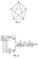
- Figure 1 illustrates a preferred arrangement of five antennas which provides ten different wide apertures between the five antennas A, B, C, D and E.
- the antennas are arranged at the apices of a regular pentagon.
- the five sides of the pentagon provide five equal apertures, the planes of which are equally spaced at 72 degrees.
- the arrangement also provides a further five equal apertures defined by the diagonals of the pentagon. Each of these diagonal apertures is parallel to one of the apertures defined by the sides of the pentagon, but the diagonal apertures are wider.
- the ten apertures represented by this array are AB, BC, CD, DE, EA, AD, AC, BE, BD and CE.
- a central antenna may also be used, to provide additional information which is particularly useful where the DF system is required to provide the elevation as well as the horizontal bearing of the received signal.
- the aperture defined by the sides of the pentagon may each be many times the wavelength of the received radio signal.
- the arrangement of five antennas in a pentagon is preferred, it is also possible to arrange more than five antennas to produce a number of wide apertures giving 360° coverage. It is preferable to arrange the antennas in a regular array to simplify the analysis. However, provided the orientation and width of the various apertures are known, it will be possible to use any irregular arrangement of the antennas provided at least five non-parallel wide apertures are reasonably evenly spread over 360°. As regards alternative regular arrangements of the antennas, it will be seen that a regular hexagon will provide only a little further information than the triangular arrays of the prior art, but significantly less information than that available from the pentagon, and therefore such an arrangement is not suitable. A regular heptagon would be acceptable, as would other regular figures with a prime number of sides. The arrangement with five antennas is, however, advantageous in that it provides good results with a small number of antennas.
- a simple DF system using an array of five antennas arranged at the apices of a regular pentagon is illustrated in Figure 2.
- the signal received from each of the antennas A, B, C, D, E is fed to respective terminals of two commutator switches 2, 4.
- the signals selected by the switches 2, 4 are fed to respective receivers 6, 8 which are tuned to the signal from the radio source the bearing of which is to be calculated.
- the intermediate frequency outputs from the respective receivers 6, 8 are fed to respective inputs of a phase differencer 10.
- the commutator switches 2, 4 are controlled so that the phase difference across each of the ten apertures defined by the antenna array is sequentially sampled.
- the phase difference for each aperture in turn is output along a line 12 to a bearing calculation device 14.
- the calculation device 14 may employ any of various calculation methods to derive the final unambiguous bearing output from the measured phase differences.
- a suitable technique is to use what will be described as the "histogram method". In this method, all the possible bearing values are calculated from the phase difference across each aperture. A histogram is then formed of the number of possible bearing values falling in each narrow range of possible bearings. By examining the resulting histogram it can be seen that a large number of possible bearing values will occur in one or more particular ranges. In ideal circumstances the number of possible bearing values at the correct bearing will equal the number of apertures analysed. However, in most radio environments there is some degree of reflection and other noise which would cause at least one aperture not to give an estimate of the bearing within the accuracy of the chosen bearing range.
- the bearings selected to be output are those ranges which contain greater than a predetermined number of possible bearing values. For example, if ten apertures are analysed then any bearing range which has accumulated more than, say, eight values is output as the bearing of a signal received at that frequency.
- a suitable width for the histogram ranges is 2° when ten apertures of a pentagonal antenna array are analysed.
- Another possible method of bearing calculation includes providing a store into which the expected phase differences across each of the apertures for a range of different bearings and different frequencies has been loaded.
- the phase differences may be derived from field measurements or by prior calculation.
- a comparison of the measured phase differences across the apertures produced on line 12 with the various sets of stored reference phase differences will produce a unique bearing output after adjustment for any difference in frequency between the actual frequency of the received radio signal and the closest reference frequency.
- the bearing calculation block 14 will include a memory in which the reference phase differences are stored.
- a preferred method of bearing calculation involves deriving the Fourier series coefficients of the spatial phase distribution, and deriving the bearing angle from the first order coefficient as discussed in more detail below in connection with the embodiment of Figure 3.
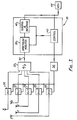
- FIG. 3 illustrates a more complex interferometer DF system utilising the antenna array as previously described.
- each of the antennas A, B, C, D, E is provided with its own receiver 20, 22, 24, 26, 28.
- Each receiver is connected to a common local oscillator 30.
- the receivers do not need to be tuned accurately to the radio signal to be received but may be arranged to receive all signals in a particular band.
- the intermediate frequency outputs from the receivers 20 to 28 are fed to a sample and hold type analogue to digital converter 32 which produces an output along the line 34 to a digital signal processor 36.
- the digital signal processor 36 includes a spectrum analyser 38 which receives the digitized output representing the signals received by each of the five antennas.
- the spectrum analyser 38 divides the band of received signals from each antenna into a number of smaller frequency intervals, referred to below as sample frequencies, and measures the amplitude and phase of the signal energy received at each of these sample frequencies.
- the phase information may be derived by including Fourier transform circuitry within the analyser 38. This circuitry takes the Fourier transform with respect to time of each antenna signal. The Fourier transform is taken over a finite time modified by a suitable window. Those skilled in the art will appreciate that various techniques may be utilised to carry out such a Fourier transform with any appropriate algorithm on the digital samples.
- the output of the Fourier transform circuitry will be equal to the product of the number of antennas and the number of sample frequencies. For example if 32 sample frequencies are used with an array of five antennas there will be 160 digital word outputs for each time interval, each representing the Fourier transform of a particular antenna signal at a particular sample frequency. The actual phase of that antenna signal at the particular sample frequency is obtained by taking the four quadrant inverse tangent of the ratio of the imaginary and real components of the Fourier transform at positive frequencies.
- phase at the mth antenna at a sample frequency ⁇ o are given by the following:
- phase information is passed to a sorting and bearing processor 40 together with the data on the amplitude of the signal received at each sample frequency.
- Processor 40 analyses the spectral energy received by each antenna to determine where in the spectrum there is a radio signal being received.
- the processor 40 may use any of the techniques so far described which operate on the phase differences across the various apertures. The required phase differences may readily be calculated by differencing the relative phases output by the spectrum analyser 38 for the respective antennas of each aperture to be analysed.
- the processor 40 includes circuitry which calculates the Fourier series coefficients of the spatial phase distribution.
- the calculated phases ⁇ (m, ⁇ o ) may be regarded as discrete samples from a continuous phase distribution created by the radio signal being received at that sample frequency.
- This continuous phase distribution may be represented as a Fourier series in accordance with well known mathematical principles.
- the Fourier coefficients A n ( ⁇ o ) may be calculated from the following formulae:
- the first order coefficient is given by:
- the first term of the above equation may be regarded as a vector the magnitude of which is half the radius of the circular array expressed in wavelengths at the sample frequency, and the phase of which is the bearing angle b, since:
- the Fourier coefficients up to an appropriate order for a number of sets of possible q(m) are stored in a random access memory RAM (not shown).
- a random access memory RAM for an array with a 4.5 wavelength radius each of the q(m) may be 0, ⁇ 1, ⁇ 2, ⁇ 3 or ⁇ 4.
- logical considerations allow a large number of these sets to be eliminated from consideration as being impossible to achieve in practice. In practice it is probably only necessary to test 60 possible sets of q(m). In the arrangement illustrated in Figure 4 the q(m) are the set (2, 1, -1, -2, 0).
- the bearing processor 40 calculates each of the Fourier coefficients from the phase data output from the spectrum analyser 38. Each of the stored coefficients is then deducted from the calculated coefficient and the result compared with a value dependent on the coefficient being considered. In the case of the zero order coefficient, the result is compared with the measured phase at the central antenna. If there is no central antenna then this coefficient is not used. For the first order coefficient, the magnitude of the result is compared with the radius of the array expressed in wavelengths. For second and higher order coefficients, where present, the result is compared in each case with zero.
- the goodness of the fit of each set of q(m) to the constraints set out above may be established by a least squares method.
- the first order Fourier coefficient of the best set of q(m) that is the set which most closely meet all the available constraints, is then subtracted from the calculated first order coefficient and the bearing angle b recovered as the four quadrant inverse tangent of the ratio of the imaginary and real parts of the result.
- alternative approaches may be used to extract b from the formula of the equation (IV) once the q(m) are known. All these approaches are considered to effectively correspond to substituting the best set of q(m) into equation (IV).
- the resulting bearing is output to the VDU 44 together with the amplitude information derived from the spectrum analyser 38.
- the goodness of fit of the magnitude Fourier coefficients using the selected set of q(m) to the stored coefficients can also be displayed as a confidence factor. It will be appreciated that if a strong signal is received at a sample frequency and there is little reflection or noise then the amplitude will be high and the second or higher order Fourier coefficients will be close to zero.
- the time windows of the analyser 38 during which the signal is received may also be displayed. It will be appreciated that various display formats may be adopted in accordance with the required use.
- the local oscillator 30, spectrum analyser 38 and sorting and bearing processor 40 are each under the control of a controller 42.
- the controller 42 determines the band of received signals to be analysed by its control of local oscillator 30. Controller 42 also determines the degree of spectrum analysis carried out by analyser 38. For example, if the frequency of the radio source to be located is known then only that portion of the received band needs to be analysed.
- the controller 42 may also determine the time period for which the output from each antenna is sampled.
- the sorting and bearing processor 40 may be capable of utilizing different algorithms for calculating the bearing and may use all or only some of the information provided from the analyser 38, for example it may analyse all the phases or only a subset of them. These features are under the control of controller 42.
- the second term in the phase equation (I) becomes: where x is the angle of elevation of the received signal. Accordingly the first order Fourier coefficient has a first term as given in equation (IV) which is similarly modified by a factor of cos (x). This introduces an uncertainty into the constraint provided by the first order Fourier coefficient as it is now only possible to eliminate those sets of q(m) which give a difference between the calculated coefficient and the coefficient of the set of q(m) which has a magnitude greater than half the radius of the array in wavelengths. This is because cos (x)
- Equation (II) the spatial phase distribution is dependent only on the received signal and it will not be modified by the disposition of the antennas.
- the zero-order coefficient will represent the phase centre of the array, and the first order coefficient will contain the bearing information.
Landscapes
- Physics & Mathematics (AREA)
- Engineering & Computer Science (AREA)
- General Physics & Mathematics (AREA)
- Radar, Positioning & Navigation (AREA)
- Remote Sensing (AREA)
- Radar Systems Or Details Thereof (AREA)
Description
- The invention relates to an interferometer type DF system, comprising a non-linear array of at least five antennas arranged so as to provide 360° coverage, phase difference means responsive to the electrical signals respectively produced by the antennas in response to a radio signal received by the array to produce signals representing the relative phases of or the phase differences between at least some of the electrical signals, and processing means responsive to the signals from the phase difference means to produce an output representing the bearing of the radio signal.
- Interferometer type DF systems use at least two spaced antennas which each receive a radio signal the bearing direction of which is to be found. Comparison of the phases of the signals received by the antennas allows a number of possible bearings for the radio source to be calculated. The multiple bearings calculated are referred to as ambiguities as only one bearing value is correct. DF systems of this type become more accurate as the spacing between the antennas is increased relative to the wavelength of the radio signal. This spacing is referred to as the "aperture". A narrow aperture system, i.e. one where the spacing between the antennas is less than one wavelength, will produce few ambiguities but may be subject to considerable error in the possible bearing values calculated, particularly in a case where a significant proportion of the signal energy is being received by the antennas after reflection from some intermediate object. A wide aperture system is more accurate but produces a large number of ambiguities.
- For example, a pair of antennas defining a narrow aperture of width equal to about a quarter of a wavelength or less will produce only one ambiguity, whereas a one wavelength aperture will produce three ambiguities and a wide aperture equal to five times the wavelength will produce 23 ambiguities. However, for a five wavelength aperture the error in the bearing will be considerably smaller than that produced by the narrow aperture even in a case where the received signal includes a relatively large reflected component.
- A single aperture is not very sensitive for detecting the bearing of a received radio signal when the source is lined up with the antennas defining the aperture.
- In order to provide 360° coverage, that is good sensitivity to radio sources at any bearing, it has been proposed to use an arrangement of three antennas in a triangular configuration, for example a right angled triangle or an equilateral triangle, in order to define two apertures transverse to one another. If the apertures between the antennas are chosen to be wide then this type of arrangement gives good sensitivity and accuracy but still produces an unacceptably large number of ambiguities. For example using an isosceles right angles triangle with the equal perpendicular apertures each approximately twice the wavelength of the radio source, ten possible bearings, some of which may be coincident, are calculated for each aperture with a typical 30 degree spacing.
- A system of the type first set forth above is known from DE-A-2 011 147. However, this system requires each antenna to be spaced less than one wavelength from its neighbours and therefore suffers from the inaccuracies discussed above if thre are few elements or must have a very large number of elements (for example, 16 or 20).
- Other examples of such systems are described in GB-1 536 996 and GB-1 455 929. These systems use large circular arrays of antennas where each antenna is spaced less than half a wavelength from its neighbour. The systems require large numbers of antennas together with complex processing procedure in order to provide sufficient accuracy.
- Systems of the type first set forth above are also known in which antennas are used having wide aperture spacing but in which the ambiguities referred to above are resolved, at least to some extent, by using, also, antennas providing a narrow aperture. The wide aperture and the narrow aperture part of the system may have separate antennas or may have one antenna in common. Typically, at least three antennas are used for each part. One such system is described in GB-A-2 101440. In the system disclosed there, the approximate but unambiguous bearing output from the narrow aperture part is compared with the multiple, ambiguous, outputs from the more accurate wide aperture parts. The closest one of the multiple outputs to the unambiguous output is selected as the bearing of the radio source. A problem encountered with such a system arises out of this comparison. For example, if the wide aperture part has an aperture equal to five wavelengths, the multiple bearing outputs will be closely spaced at, typically, 7.2 degrees. If the narrow aperture part had an error of greater than half this angular spacing, it is possible for the wrong one of the multiple wide aperture bearings to be chosen as the correct bearing value.
- The invention is therefore concerned with solving the problem of providing a direction finding system giving an accurate unambiguous output without an excessive number of antennas.
- Accordingly, the system as first set forth above is characterised, in accordance with the invention, in that the spacing between any pair of the antennas is greater than a wavelength of th8 radio signal, and in that the processing means calculate the unambiguous bearing of the radio signal from the relative phases or phase differences alone by multiple comparison of them with each other or with pre-stored values.
- Interferometer-type direction finding (DF) systems embodying the invention will now be described, by way of example only, with reference to the accompanying diagrammatic drawings in which:
- Figure 1 is a diagram illustrating the arrangement of antennas for use in the interferometer type DF systems;
- Figure 2 is a block circuit diagram of a first embodiment of a DF system;
- Figure 3 is a block diagram of another DF system; and
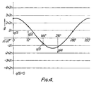
- Figure 4 is a diagram illustrating the measured phases <I> at each antenna relative to an angular spatial coordinate m.
- Figure 1 illustrates a preferred arrangement of five antennas which provides ten different wide apertures between the five antennas A, B, C, D and E. The antennas are arranged at the apices of a regular pentagon. The five sides of the pentagon provide five equal apertures, the planes of which are equally spaced at 72 degrees. The arrangement also provides a further five equal apertures defined by the diagonals of the pentagon. Each of these diagonal apertures is parallel to one of the apertures defined by the sides of the pentagon, but the diagonal apertures are wider. The ten apertures represented by this array are AB, BC, CD, DE, EA, AD, AC, BE, BD and CE. In a variation, a central antenna may also be used, to provide additional information which is particularly useful where the DF system is required to provide the elevation as well as the horizontal bearing of the received signal.
- As will be appreciated the possible
horizontal bearing values 6, which can be calculated from the phase difference across a single wide aperture are given by the solutions to the equation:
- d is the width of the aperture in wavelengths of the received signal, and
- n takes the integer values from 0 to N successively where N is the largest integer such that N+p'<d.
- It has been found that by comparing the phase differences between the signals received at the two antennas of each of the ten apertures, a unique bearing for the radio source can be calculated to the maximum accuracy of the widest aperture. For a five antenna array as depicted, the aperture defined by the sides of the pentagon may each be many times the wavelength of the received radio signal.
- Although the arrangement of five antennas in a pentagon is preferred, it is also possible to arrange more than five antennas to produce a number of wide apertures giving 360° coverage. It is preferable to arrange the antennas in a regular array to simplify the analysis. However, provided the orientation and width of the various apertures are known, it will be possible to use any irregular arrangement of the antennas provided at least five non-parallel wide apertures are reasonably evenly spread over 360°. As regards alternative regular arrangements of the antennas, it will be seen that a regular hexagon will provide only a little further information than the triangular arrays of the prior art, but significantly less information than that available from the pentagon, and therefore such an arrangement is not suitable. A regular heptagon would be acceptable, as would other regular figures with a prime number of sides. The arrangement with five antennas is, however, advantageous in that it provides good results with a small number of antennas.
- A simple DF system using an array of five antennas arranged at the apices of a regular pentagon is illustrated in Figure 2. The signal received from each of the antennas A, B, C, D, E is fed to respective terminals of two
commutator switches switches respective receivers respective receivers phase differencer 10. Thecommutator switches line 12 to a bearing calculation device 14. - The calculation device 14 may employ any of various calculation methods to derive the final unambiguous bearing output from the measured phase differences. A suitable technique is to use what will be described as the "histogram method". In this method, all the possible bearing values are calculated from the phase difference across each aperture. A histogram is then formed of the number of possible bearing values falling in each narrow range of possible bearings. By examining the resulting histogram it can be seen that a large number of possible bearing values will occur in one or more particular ranges. In ideal circumstances the number of possible bearing values at the correct bearing will equal the number of apertures analysed. However, in most radio environments there is some degree of reflection and other noise which would cause at least one aperture not to give an estimate of the bearing within the accuracy of the chosen bearing range. The bearings selected to be output are those ranges which contain greater than a predetermined number of possible bearing values. For example, if ten apertures are analysed then any bearing range which has accumulated more than, say, eight values is output as the bearing of a signal received at that frequency. A suitable width for the histogram ranges is 2° when ten apertures of a pentagonal antenna array are analysed.
- It will be appreciated that it is not necessary to utilise all the information provided by the antenna array. For example only a subset of the ten apertures need be analysed. The use of the wider diagonal apertures will produce more ambiguities and greater accuracy than the narrower apertures forming the sides of the pentagon.
- Another possible method of bearing calculation includes providing a store into which the expected phase differences across each of the apertures for a range of different bearings and different frequencies has been loaded. The phase differences may be derived from field measurements or by prior calculation. A comparison of the measured phase differences across the apertures produced on
line 12 with the various sets of stored reference phase differences will produce a unique bearing output after adjustment for any difference in frequency between the actual frequency of the received radio signal and the closest reference frequency. In this method the bearing calculation block 14 will include a memory in which the reference phase differences are stored. - A preferred method of bearing calculation involves deriving the Fourier series coefficients of the spatial phase distribution, and deriving the bearing angle from the first order coefficient as discussed in more detail below in connection with the embodiment of Figure 3.
- Figure 3 illustrates a more complex interferometer DF system utilising the antenna array as previously described. In this case each of the antennas A, B, C, D, E is provided with its
own receiver local oscillator 30. In this system the receivers do not need to be tuned accurately to the radio signal to be received but may be arranged to receive all signals in a particular band. The intermediate frequency outputs from thereceivers 20 to 28 are fed to a sample and hold type analogue todigital converter 32 which produces an output along theline 34 to adigital signal processor 36. - The
digital signal processor 36 includes a spectrum analyser 38 which receives the digitized output representing the signals received by each of the five antennas. The spectrum analyser 38 divides the band of received signals from each antenna into a number of smaller frequency intervals, referred to below as sample frequencies, and measures the amplitude and phase of the signal energy received at each of these sample frequencies. The phase information may be derived by including Fourier transform circuitry within the analyser 38. This circuitry takes the Fourier transform with respect to time of each antenna signal. The Fourier transform is taken over a finite time modified by a suitable window. Those skilled in the art will appreciate that various techniques may be utilised to carry out such a Fourier transform with any appropriate algorithm on the digital samples. The output of the Fourier transform circuitry will be equal to the product of the number of antennas and the number of sample frequencies. For example if 32 sample frequencies are used with an array of five antennas there will be 160 digital word outputs for each time interval, each representing the Fourier transform of a particular antenna signal at a particular sample frequency. The actual phase of that antenna signal at the particular sample frequency is obtained by taking the four quadrant inverse tangent of the ratio of the imaginary and real components of the Fourier transform at positive frequencies. - For an m antenna array as illustrated in Figure 1 and also used in the present embodiment the phase at the mth antenna at a sample frequency ωo are given by the following:

- T=time reference of radio source
- R=rωo/c
- r=radius of array
- c=velocity of propagation
- d=(π/2)-b
- b=bearing angle and q(m) is an unknown integer such that | φ(m, ωo) | ≤π. It should be noted that the phase estimated in this way is in effect the phase of the antenna signal with respect to a virtual reference signal cos (OOot). The 2nq(m) term arises because a reference signal cos(Mot) is indistinguishable from a reference signal cos(wot-2nq(m)). Figure 4 illustrates the phases measured at the antennas. Since the antennas are assumed to be on the periphery of a circle their position can be represented by an angular spatial coordinate m which in the illustrated example represents the number of the antenna in the range 1 to 5. Alternatively it may be considered as the angle between a fixed radius and a radius to each antenna in turn measured in units of 72°. The measured phases modulo 2n are the difference between the illustrated phase and the associated 2nq(m).
- The phase information is passed to a sorting and bearing
processor 40 together with the data on the amplitude of the signal received at each sample frequency. -
Processor 40 analyses the spectral energy received by each antenna to determine where in the spectrum there is a radio signal being received. Theprocessor 40 may use any of the techniques so far described which operate on the phase differences across the various apertures. The required phase differences may readily be calculated by differencing the relative phases output by the spectrum analyser 38 for the respective antennas of each aperture to be analysed. - In a preferred embodiment the
processor 40 includes circuitry which calculates the Fourier series coefficients of the spatial phase distribution. The calculated phases φ(m, ωo) may be regarded as discrete samples from a continuous phase distribution created by the radio signal being received at that sample frequency. This continuous phase distribution may be represented as a Fourier series in accordance with well known mathematical principles. Thus:

- From this formula the zero order coefficient where n=0 reduces to the average of the antenna phases. It will be noted that the summation only covers the phases of the antennas on the periphery of the circular array. The zero order coefficient gives the phase centre of the array. Where a central antenna is provided then the measured phase at the central antenna should be equal to this zero order coefficient.
- The first order coefficient is given by:

- Substituting for (p from equation (I) above and using the result that Σmexp(+j2πm/M)=0 we obtain:
- A1(ωo)=1/MΣmRsin(d+2πm/M)exp(j2µm/M)+2πq(m)exp(j2πm/M) expanding the sine factor into complex exponential form and utilising the previous result this gives:

- =Rj/2 exp(-jd)+1/MEm2rtq(m)exp(j2n m/M) (IV)
- The first term of the above equation may be regarded as a vector the magnitude of which is half the radius of the circular array expressed in wavelengths at the sample frequency, and the phase of which is the bearing angle b, since:

- The second term of equation (IV) is effectively the first order Fourier coefficient of the phase components due to the integral multiples of 2n in the actual antenna phases which cannot be measured.
- For the case of five antennas there is also a second order Fourier coefficient. It can be shown that if there are no reflections or other interference then this coefficient should be equal to zero. This can be appreciated since a radio wave spaced far from the source should have a pure linear spatial phase distribution with respect to the source. By considering the effect of superimposing a circular array on said linear phase distribution it can be seen that the only non-zero Fourier coefficient should then be the first order coefficient. For seven antennas the third order coefficient can be calculated, and so on.
- In order to determine the q(m) of the antenna phases, the Fourier coefficients up to an appropriate order for a number of sets of possible q(m) are stored in a random access memory RAM (not shown). For an array with a 4.5 wavelength radius each of the q(m) may be 0, ±1, ±2, ±3 or ±4. For five antennas this gives 59 or 1953125 possible sets of q(m). However logical considerations allow a large number of these sets to be eliminated from consideration as being impossible to achieve in practice. In practice it is probably only necessary to test 60 possible sets of q(m). In the arrangement illustrated in Figure 4 the q(m) are the set (2, 1, -1, -2, 0).
- The bearing
processor 40 calculates each of the Fourier coefficients from the phase data output from the spectrum analyser 38. Each of the stored coefficients is then deducted from the calculated coefficient and the result compared with a value dependent on the coefficient being considered. In the case of the zero order coefficient, the result is compared with the measured phase at the central antenna. If there is no central antenna then this coefficient is not used. For the first order coefficient, the magnitude of the result is compared with the radius of the array expressed in wavelengths. For second and higher order coefficients, where present, the result is compared in each case with zero. - The goodness of the fit of each set of q(m) to the constraints set out above may be established by a least squares method. The first order Fourier coefficient of the best set of q(m), that is the set which most closely meet all the available constraints, is then subtracted from the calculated first order coefficient and the bearing angle b recovered as the four quadrant inverse tangent of the ratio of the imaginary and real parts of the result. It will be appreciated that alternative approaches may be used to extract b from the formula of the equation (IV) once the q(m) are known. All these approaches are considered to effectively correspond to substituting the best set of q(m) into equation (IV).
- For each sample frequency the resulting bearing is output to the
VDU 44 together with the amplitude information derived from the spectrum analyser 38. The goodness of fit of the magnitude Fourier coefficients using the selected set of q(m) to the stored coefficients can also be displayed as a confidence factor. It will be appreciated that if a strong signal is received at a sample frequency and there is little reflection or noise then the amplitude will be high and the second or higher order Fourier coefficients will be close to zero. The time windows of the analyser 38 during which the signal is received may also be displayed. It will be appreciated that various display formats may be adopted in accordance with the required use. - The
local oscillator 30, spectrum analyser 38 and sorting and bearingprocessor 40 are each under the control of acontroller 42. Thecontroller 42 determines the band of received signals to be analysed by its control oflocal oscillator 30.Controller 42 also determines the degree of spectrum analysis carried out by analyser 38. For example, if the frequency of the radio source to be located is known then only that portion of the received band needs to be analysed. Thecontroller 42 may also determine the time period for which the output from each antenna is sampled. The sorting and bearingprocessor 40 may be capable of utilizing different algorithms for calculating the bearing and may use all or only some of the information provided from the analyser 38, for example it may analyse all the phases or only a subset of them. These features are under the control ofcontroller 42. - So far it has been assumed that the radio signal is propagating towards the antenna array substantially horizontally. However HF transmissions may be reflected off the ionosphere and therefore be received from elevations of typically 60°-70°. If this elevation can be measured together with the horizontal bearing then a position fix on the radio source can be obtained.
- It can be shown that the second term in the phase equation (I) becomes:

- The analysis has so far been described in relation to a circular array of equally spaced antennas where the phase at each antenna has the form given in equation (1). However, it will be appreciated that the described method can be used for other non-linear arrangements of antennas provided the relative spatial positions of the antennas making up the array are known. The second term of the phase equation (I) will then generally have a more complex form but the 2nq(m) term will still be present. It will also generally be necessary to use two spatial coordinates to define the position of each antenna rather than merely the coordinate m used in equations (I) and (11) above. It is therefore necessary to consider a Fourier series in two dimensions.
- The information contained in the various order Fourier coefficients will, however, be the same. It can be seen from equation (II) that the spatial phase distribution is dependent only on the received signal and it will not be modified by the disposition of the antennas. For example the zero-order coefficient will represent the phase centre of the array, and the first order coefficient will contain the bearing information.
- It will be appreciated that regular circular array will not always be possible to achieve in practice. For example, the lie of the ground may make it necessary for the antennas to be unevenly spaced about a circle. If the constant radius can be maintained it is only necessary to define m more accurately, say in degrees from a reference radius. In the arrangement illustrated in Fig. 4 the values m=1 to 5 would become m=0,72°, 144°, 216° and 288° respectively and M instead of 5 would be 360°. Thus the actual angular positions of the five antennas would be used instead of those set out above. The summation would then be over the whole range of 360° but as only five values of the phase are known the factor 1/M remains 1/5. Otherwise the processing and the significance of the Fourier coefficients will remain the same. It can be seen from Figure 4 that if the positions of the antennas are shifted angularly, the measured phases will be different and possibly also the q(m) but the spatial phase distribution is unaltered.
Claims (11)
Applications Claiming Priority (2)
| Application Number | Priority Date | Filing Date | Title |
|---|---|---|---|
| GB8312942 | 1983-05-11 | ||
| GB08312942A GB2140238A (en) | 1983-05-11 | 1983-05-11 | Direction finding |
Publications (3)
| Publication Number | Publication Date |
|---|---|
| EP0125838A2 EP0125838A2 (en) | 1984-11-21 |
| EP0125838A3 EP0125838A3 (en) | 1986-05-14 |
| EP0125838B1 true EP0125838B1 (en) | 1990-03-21 |
Family
ID=10542537
Family Applications (1)
| Application Number | Title | Priority Date | Filing Date |
|---|---|---|---|
| EP84302971A Expired EP0125838B1 (en) | 1983-05-11 | 1984-05-03 | Direction finding |
Country Status (4)
| Country | Link |
|---|---|
| US (1) | US4639733A (en) |
| EP (1) | EP0125838B1 (en) |
| DE (1) | DE3481730D1 (en) |
| GB (1) | GB2140238A (en) |
Cited By (2)
| Publication number | Priority date | Publication date | Assignee | Title |
|---|---|---|---|---|
| DE10163455A1 (en) * | 2001-12-25 | 2003-08-21 | Detlef Mansel | Determining direction of mobile radio transmission, by activating sub-groups comprising combinations of antennas in rapid succession and using phase shifts to locate source |
| RU2752249C2 (en) * | 2020-12-08 | 2021-07-23 | Акционерное общество "Научно-исследовательский институт "Вектор" (АО "НИИ "Вектор") | Multichannel direction finder of rf radio signals |
Families Citing this family (82)
| Publication number | Priority date | Publication date | Assignee | Title |
|---|---|---|---|---|
| DE3587428T2 (en) * | 1984-10-12 | 1993-10-14 | British Aerospace | Signal processing and radio distance measuring device. |
| GB2189363A (en) * | 1986-04-18 | 1987-10-21 | Philips Electronic Associated | Radio direction-finding |
| US4717916A (en) * | 1986-05-16 | 1988-01-05 | Holodyne Ltd., 1986 | High resolution imaging doppler interferometer |
| US5321410A (en) * | 1988-06-09 | 1994-06-14 | Southwest Research Institute | Adaptive doppler DF system |
| US4975710A (en) * | 1989-08-01 | 1990-12-04 | Baghdady Elie J | Methods and apparatus for direction of arrival measurement and radio navigation aids |
| CA2026342A1 (en) * | 1989-09-29 | 1991-03-30 | Juval Mantel | Sonic direction locating system |
| US4992796A (en) * | 1990-02-20 | 1991-02-12 | Lockheed Sanders, Inc. | Computed-interferometry radar system with coherent integration |
| US5093649A (en) * | 1990-08-28 | 1992-03-03 | The Boeing Company | Bessel beam radar system using sequential spatial modulation |
| US5373236A (en) * | 1993-07-01 | 1994-12-13 | The United States Of America As Represented By The Secretary Of The Air Force | Highly accurate zero crossings for frequency determination |
| US5327144A (en) * | 1993-05-07 | 1994-07-05 | Associated Rt, Inc. | Cellular telephone location system |
| FR2718246B1 (en) * | 1994-03-29 | 1996-04-26 | Thomson Csf | Method and device for simultaneous narrowband direction finding. |
| US5581620A (en) * | 1994-04-21 | 1996-12-03 | Brown University Research Foundation | Methods and apparatus for adaptive beamforming |
| US5568154A (en) * | 1995-05-22 | 1996-10-22 | State Of Israel-Ministry Of Defense Armament Development Authority-Rafael | System and a method for the instantaneous determination of the frequencies and angles of arrival of simultaneously incoming RF signals |
| US6658234B1 (en) * | 1995-06-02 | 2003-12-02 | Northrop Grumman Corporation | Method for extending the effective dynamic range of a radio receiver system |
| US6018317A (en) * | 1995-06-02 | 2000-01-25 | Trw Inc. | Cochannel signal processing system |
| US5771019A (en) * | 1996-09-09 | 1998-06-23 | Hughes Electronics Corporation | Method and system for determining the location of a sense antenna associated with a phased array communication system |
| US5890068A (en) * | 1996-10-03 | 1999-03-30 | Cell-Loc Inc. | Wireless location system |
| US5874918A (en) * | 1996-10-07 | 1999-02-23 | Lockheed Martin Corporation | Doppler triangulation transmitter location system |
| US5835060A (en) * | 1996-10-07 | 1998-11-10 | Lockheed Martin Corporation | Self-resolving LBI triangulation |
| US5973643A (en) * | 1997-04-11 | 1999-10-26 | Corsair Communications, Inc. | Method and apparatus for mobile emitter location |
| US5898402A (en) * | 1997-05-30 | 1999-04-27 | Federal Communications Commission/Compliance And Information Bureau/Equipment Development Group | Wide aperature radio frequency data acquisition system |
| US6201499B1 (en) | 1998-02-03 | 2001-03-13 | Consair Communications | Time difference of arrival measurement system |
| KR100295896B1 (en) * | 1998-06-09 | 2001-10-26 | 이광환 | Antenna station and method for receiving short pulses, and apparatus for detecting wireless signal origination location using the method and method |
| SE512219C2 (en) * | 1998-06-15 | 2000-02-14 | Jan Bergman | Method and system for obtaining direction for an elliptically polarized electromagnetic wave propagation |
| US6330452B1 (en) | 1998-08-06 | 2001-12-11 | Cell-Loc Inc. | Network-based wireless location system to position AMPs (FDMA) cellular telephones, part I |
| US6208297B1 (en) | 1998-10-09 | 2001-03-27 | Cell-Loc Inc. | Methods and apparatus to position a mobile receiver using downlink signals, part I |
| US6204812B1 (en) | 1998-10-09 | 2001-03-20 | Cell-Loc Inc. | Methods and apparatus to position a mobile receiver using downlink signals, part II |
| US6266014B1 (en) | 1998-10-09 | 2001-07-24 | Cell-Loc Inc. | Methods and apparatus to position a mobile receiver using downlink signals part IV |
| US6169519B1 (en) * | 1999-09-21 | 2001-01-02 | Rockwell Collins, Inc. | TCAS bearing measurement receiver apparatus with phase error compensation method |
| US6255991B1 (en) * | 2000-01-19 | 2001-07-03 | Trw Inc. | Low cost angle of arrival measurement system |
| FR2805614B1 (en) * | 2000-02-25 | 2003-08-22 | Thomson Csf | METHOD FOR LOCATING RADIO SOURCES USING A TWO-CHANNEL HIGH RESOLUTION RADIOGONIOMETER |
| US6449216B1 (en) | 2000-08-11 | 2002-09-10 | Phonak Ag | Method for directional location and locating system |
| US6687187B2 (en) * | 2000-08-11 | 2004-02-03 | Phonak Ag | Method for directional location and locating system |
| RU2218580C2 (en) * | 2001-03-16 | 2003-12-10 | Федеральное государственное унитарное предприятие "Ростовский-на-Дону научно-исследовательский институт радиосвязи" | Method of direction finding of radio emission sources when scanner assembly is located on surface of mobile carrier ( variants ); direction finder of radio signals of radio emission sources when scanner assembly is mounted on surface of mobile carrier ( variants ) |
| RU2208808C2 (en) * | 2001-10-04 | 2003-07-20 | Войсковая часть 25714 | Omnidirectional radio direction finder |
| RU2201599C1 (en) * | 2002-06-27 | 2003-03-27 | Рембовский Анатолий Маркович | Method of direction finding of radio signals and direction finder for its realization |
| US6778148B1 (en) | 2002-12-04 | 2004-08-17 | The United States Of America As Represented By The Secretary Of The Navy | Sensor array for enhanced directivity |
| RU2251707C2 (en) * | 2003-03-25 | 2005-05-10 | 5 Центральный научно-исследовательский испытательный институт Министерства обороны Российской Федерации (5 ЦНИИИ МО РФ) | Mode of taking bearings of a radio signal's source |
| RU2267134C2 (en) * | 2003-12-03 | 2005-12-27 | Федеральное государственное унитарное предприятие "Ростовский-на-Дону научно-исследовательский институт радиосвязи" | Mode of direction finding of radio signals and a direction finder of radio signals |
| RU2263927C2 (en) * | 2004-01-14 | 2005-11-10 | Открытое акционерное общество "Корпорация "Фазотрон-Научно-исследовательский институт радиостроения" | Method of evaluating parameters of trajectory of radio-frequency radiation sources in two-positioned passive goniometrical radar station |
| RU2263327C1 (en) * | 2004-01-15 | 2005-10-27 | Терентьев Алексей Васильевич | Method for radio signals position-finding and direction-finder for realization of said method |
| RU2262119C1 (en) * | 2004-03-24 | 2005-10-10 | Федеральное государственное унитарное предприятие "Воронежский научно-исследовательский институт связи" | Method for direction finding of radio signals |
| RU2260814C1 (en) * | 2004-05-13 | 2005-09-20 | Федеральное государственное унитарное предприятие "Таганрогский научно-исследовательский институт связи" (ФГУП "ТНИИС") | Method for automatic inspection of radio-frequency emission sources |
| KR101244440B1 (en) | 2004-07-02 | 2013-03-18 | 트랙맨 에이/에스 | A method and an apparatus for determining a deviation between an actual direction of a launched projectile and a predetermined direction |
| RU2283505C1 (en) * | 2005-01-31 | 2006-09-10 | Алексей Васильевич Терентьев | Method and device for determining coordinates of a radio radiation source |
| US10393870B2 (en) | 2005-03-03 | 2019-08-27 | Trackman A/S | Determination of spin parameters of a sports ball |
| US7427954B2 (en) * | 2005-04-07 | 2008-09-23 | Bae Systems Information And Electronic Systems Integration Inc. | Method and apparatus for direction finding |
| RU2290658C1 (en) * | 2005-05-20 | 2006-12-27 | Виктор Иванович Дикарев | Phase mode of direction finding and phase direction finder for its execution |
| RU2305294C2 (en) * | 2005-10-27 | 2007-08-27 | Открытое акционерное общество "Воронежское центральное конструкторское бюро "Полюс" (ОАО "ВЦКБ "Полюс") | Method for direction finding with regard to correlation interaction between beams |
| RU2296341C1 (en) * | 2005-11-24 | 2007-03-27 | Алексей Васильевич Терентьев | Mode of definition of the coordinates of a radiation source |
| RU2311657C1 (en) * | 2006-03-29 | 2007-11-27 | Открытое акционерное общество "Концерн "Созвездие" | Receiving device for analyzing electromagnetic situation |
| RU2317566C1 (en) * | 2006-06-27 | 2008-02-20 | ОАО "Конструкторское бюро "Лианозовские радары" | Mode of measuring of angular attitude of radar targets with a two-coordinate radar of meter range |
| RU2316784C1 (en) * | 2006-07-19 | 2008-02-10 | Закрытое акционерное общество "ИРКОС" | Method for determining position of a transmitter by means of mobile direction-finder |
| US7576686B2 (en) * | 2006-08-07 | 2009-08-18 | Garmin International, Inc. | Method and system for calibrating an antenna array for an aircraft surveillance system |
| US7439901B2 (en) * | 2006-08-08 | 2008-10-21 | Garmin International, Inc. | Active phased array antenna for aircraft surveillance systems |
| US20080055150A1 (en) * | 2006-09-06 | 2008-03-06 | Garmin International, Inc. | Method and system for detecting and decoding air traffic control reply signals |
| US7825858B2 (en) * | 2007-02-28 | 2010-11-02 | Garmin International, Inc. | Methods and systems for frequency independent bearing detection |
| US20080284637A1 (en) * | 2007-02-28 | 2008-11-20 | Garmin International, Inc. | Digital tas transmitter and receiver systems and methods |
| RU2341811C1 (en) * | 2007-07-17 | 2008-12-20 | ВОЕННАЯ АКАДЕМИЯ СВЯЗИ имени С.М. Буденного | Method of finding direction of radio signals and direction finder to this end |
| RU2365931C2 (en) * | 2007-10-08 | 2009-08-27 | Институт Прикладной Астрономии Российской Академии Наук | Phase direction finding technique, phase direction-finder therefor |
| RU2357266C1 (en) * | 2007-11-29 | 2009-05-27 | Государственное образовательное учреждение высшего профессионального образования Тамбовское высшее военное авиационное инженерное училище радиоэлектроники (военный институт) | Method of forming route for location finder carrier, which locates position of emitter |
| RU2351944C1 (en) * | 2007-12-28 | 2009-04-10 | Федеральное Государственное Образовательное Учреждение Высшего Профессионального Образования "Южный Федеральный Университет" | Method for automated control of impulse radiation sources |
| JP5309569B2 (en) * | 2008-01-11 | 2013-10-09 | ソニー株式会社 | Direction detection system |
| RU2346288C1 (en) * | 2008-01-23 | 2009-02-10 | Александр Дмитриевич Виноградов | Method for radio direction finding and direction finder for implementation thereof |
| RU2373549C1 (en) * | 2008-05-28 | 2009-11-20 | Государственное образовательное учреждение высшего профессионального образования Тамбовское высшее военное авиационное инженерное училище радиоэлектроники (военный институт) | Method of forming route of direction finder carrier, which determines location of stationary radiator |
| FR2934936B1 (en) * | 2008-08-08 | 2010-09-17 | Thales Sa | FAST SCAN RECEIVER FOR ELECTROMAGNETIC SPECTRUM MONITORING AND METHOD FOR IMPLEMENTING THE RECEIVER. |
| KR101845503B1 (en) | 2009-01-29 | 2018-04-04 | 트랙맨 에이/에스 | An assembly comprising a radar and an imaging element |
| KR20110126939A (en) * | 2010-05-18 | 2011-11-24 | 주식회사 만도 | Integrated Radar System and Vehicle Control System |
| RU2458360C1 (en) * | 2010-12-16 | 2012-08-10 | Общество с ограниченной ответственностью "Специальный Технологический Центр" | Method and device to detect coordinates of radio-frequency emission source |
| RU2467344C1 (en) * | 2011-05-06 | 2012-11-20 | Государственное Образовательное Учреждение Высшего Профессионального Образования "Московский Государственный Технический Университет Имени Н.Э. Баумана" | Method of determining bearings and amplitude of signal from radio source using direction finder with non-synchronised channels |
| EP2605036B1 (en) * | 2011-12-16 | 2019-10-23 | Trackman A/S | A method and a sensor for determining a direction-of-arrival of impingent radiation |
| US20140225590A1 (en) * | 2012-01-20 | 2014-08-14 | Arinc Incorporated | Method and system for implementing remote spectrum analysis |
| RU2516688C1 (en) * | 2012-11-13 | 2014-05-20 | Федеральное государственное автономное образовательное учреждение высшего профессионального образования "Балтийский Федеральный Университет имени Иммануила Канта" (БФУ им. И. Канта) | Method of finding direction of ionospheric signals in beam interference conditions |
| RU2530320C2 (en) * | 2013-01-22 | 2014-10-10 | Федеральное государственное бюджетное образовательное учреждение высшего профессионального образования "Воронежский государственный технический университет" | Formation method of virtual signal receiving channels |
| US10177451B1 (en) | 2014-08-26 | 2019-01-08 | Ball Aerospace & Technologies Corp. | Wideband adaptive beamforming methods and systems |
| RU2617127C1 (en) * | 2016-03-28 | 2017-04-21 | Федеральное государственное казенное военное образовательное учреждение высшего образования "Военный учебно-научный центр Военно-воздушных сил "Военно-воздушная академия имени профессора Н.Е. Жуковского и Ю.А. Гагарина" (г. Воронеж) Министерства обороны Российской Федерации | Method of forming route of direction finder carrier |
| US10379214B2 (en) | 2016-07-11 | 2019-08-13 | Trackman A/S | Device, system and method for tracking multiple projectiles |
| EP3285083B1 (en) * | 2016-08-19 | 2019-06-12 | Rohde & Schwarz GmbH & Co. KG | Method for direction finding and direction finding antenna unit |
| US10444339B2 (en) | 2016-10-31 | 2019-10-15 | Trackman A/S | Skid and roll tracking system |
| US10989791B2 (en) | 2016-12-05 | 2021-04-27 | Trackman A/S | Device, system, and method for tracking an object using radar data and imager data |
| RU2674007C1 (en) * | 2017-12-11 | 2018-12-04 | Андрей Викторович Быков | Located at big elevation angles radar targets elevation angle measuring method |
| CN108845290B (en) * | 2018-03-28 | 2022-08-02 | 哈尔滨工程大学 | Method for resisting phase ambiguity of ultra-short baseline array |
Family Cites Families (14)
| Publication number | Priority date | Publication date | Assignee | Title |
|---|---|---|---|---|
| JPS5210633B1 (en) * | 1968-09-05 | 1977-03-25 | ||
| DE2011147C3 (en) * | 1970-03-10 | 1979-04-05 | Licentia Patent-Verwaltungs-Gmbh, 6000 Frankfurt | DF method |
| DE2113883C2 (en) * | 1971-03-23 | 1982-09-30 | Licentia Patent-Verwaltungs-Gmbh, 6000 Frankfurt | DF method |
| FR2134136B2 (en) * | 1971-04-21 | 1974-04-05 | Cit Alcatel | |
| US3887923A (en) * | 1973-06-26 | 1975-06-03 | Us Navy | Radio-frequency holography |
| DE2358585C3 (en) * | 1973-11-24 | 1979-11-15 | Standard Elektrik Lorenz Ag, 7000 Stuttgart | Radio direction finder and radio beacon working according to the reciprocity law |
| FR2294589A1 (en) * | 1974-12-10 | 1976-07-09 | Cit Alcatel | TRACK TRAINING DEVICE USING DETECTORS DISTRIBUTED ON A CIRCULAR BASIS |
| GB1536996A (en) * | 1977-03-25 | 1978-12-29 | Philips Electronic Associated | Radio interferometer system |
| US4333170A (en) * | 1977-11-21 | 1982-06-01 | Northrop Corporation | Acoustical detection and tracking system |
| US4209791A (en) * | 1978-10-05 | 1980-06-24 | Anaren Microwave, Incorporated | Antenna apparatus for bearing angle determination |
| GB2064257B (en) * | 1978-10-13 | 1983-03-09 | Marconi Co Ltd | Radio direction finders |
| US4203114A (en) * | 1978-11-13 | 1980-05-13 | Anaren Microwave, Inc. | Digital bearing indicator |
| US4387376A (en) * | 1980-11-17 | 1983-06-07 | The United States Of America As Represented By The Secretary Of The Army | Phase linear interferometer system and method |
| GB2140558B (en) * | 1982-12-22 | 1986-09-17 | Mcmichael Ltd | Acoustic direction finding systems |
-
1983
- 1983-05-11 GB GB08312942A patent/GB2140238A/en not_active Withdrawn
-
1984
- 1984-05-03 DE DE8484302971T patent/DE3481730D1/en not_active Expired - Lifetime
- 1984-05-03 EP EP84302971A patent/EP0125838B1/en not_active Expired
- 1984-05-11 US US06/609,232 patent/US4639733A/en not_active Expired - Lifetime
Cited By (2)
| Publication number | Priority date | Publication date | Assignee | Title |
|---|---|---|---|---|
| DE10163455A1 (en) * | 2001-12-25 | 2003-08-21 | Detlef Mansel | Determining direction of mobile radio transmission, by activating sub-groups comprising combinations of antennas in rapid succession and using phase shifts to locate source |
| RU2752249C2 (en) * | 2020-12-08 | 2021-07-23 | Акционерное общество "Научно-исследовательский институт "Вектор" (АО "НИИ "Вектор") | Multichannel direction finder of rf radio signals |
Also Published As
| Publication number | Publication date |
|---|---|
| GB2140238A (en) | 1984-11-21 |
| US4639733A (en) | 1987-01-27 |
| EP0125838A3 (en) | 1986-05-14 |
| DE3481730D1 (en) | 1990-04-26 |
| EP0125838A2 (en) | 1984-11-21 |
Similar Documents
| Publication | Publication Date | Title |
|---|---|---|
| US4639733A (en) | Direction finding | |
| US4975710A (en) | Methods and apparatus for direction of arrival measurement and radio navigation aids | |
| Reegen | SigSpec: I. Frequency-and phase-resolved significance in Fourier space | |
| Schmidt et al. | Complementary code and digital filtering for detection of weak VHF radar signals from the mesosphere | |
| US5075619A (en) | Method and apparatus for measuring the frequency of a spectral line | |
| CA2138184C (en) | Phase noise measurement system and method | |
| US6313794B1 (en) | Method of detection and determining an angular location of frequency agile emitters | |
| US6255991B1 (en) | Low cost angle of arrival measurement system | |
| US6411249B1 (en) | Apparatus and method for the monopulse linking of frequency agile emitter pulses intercepted in on single interferometer baseline | |
| Richard et al. | VHF‐UHF interferometric measurements, applications to lightning discharge mapping | |
| EP0638811B1 (en) | Estimator of amplitude and frequency of a noisy biased sinusoid from short bursts of samples | |
| US5559516A (en) | Dual cancellation interferometric AMTI radar | |
| Poole | Advanced sounding: 1. The FMCW alternative | |
| US20100069030A1 (en) | Frequency measuring broadband digital receiver | |
| EP0615659A1 (en) | Method for field monitoring of a phased array microwave landing system far field antenna pattern employing a near field correction technique. | |
| US5559517A (en) | Maximized/minimized phase calculator for an interferometric amti radar | |
| EP0268519B1 (en) | System of processing signals drowned in a noise and its application to fringe laser velocimetry | |
| Keller et al. | Search for the Epoch of Reionization with HERA: upper limits on the closure phase delay power spectrum | |
| Paul et al. | The interpretation of ionospheric radio drift measurements—VI. Angle-of-arrival and group path [echolocation] measurements from digitized ionospheric soundings: The group path vector | |
| KR970010876B1 (en) | Interferometry with multipath nulling | |
| Brown et al. | Rotation measures of compact sources in the Canadian Galactic Plane Survey | |
| US6111543A (en) | Method and device for analysing radio navigation signals | |
| USH292H (en) | Apparatus for the detection of angles-of-arrival of radio frequency signals | |
| RU2154837C1 (en) | Method of detection of linear frequency-modulated signal with unspecified parameters | |
| RU2117954C1 (en) | Signal-to-noise ratio meter |
Legal Events
| Date | Code | Title | Description |
|---|---|---|---|
| PUAI | Public reference made under article 153(3) epc to a published international application that has entered the european phase |
Free format text: ORIGINAL CODE: 0009012 |
|
| AK | Designated contracting states |
Designated state(s): DE FR GB NL |
|
| PUAL | Search report despatched |
Free format text: ORIGINAL CODE: 0009013 |
|
| AK | Designated contracting states |
Kind code of ref document: A3 Designated state(s): DE FR GB NL |
|
| 17P | Request for examination filed |
Effective date: 19860916 |
|
| 17Q | First examination report despatched |
Effective date: 19880513 |
|
| GRAA | (expected) grant |
Free format text: ORIGINAL CODE: 0009210 |
|
| AK | Designated contracting states |
Kind code of ref document: B1 Designated state(s): DE FR GB NL |
|
| REF | Corresponds to: |
Ref document number: 3481730 Country of ref document: DE Date of ref document: 19900426 |
|
| ET | Fr: translation filed | ||
| PLBE | No opposition filed within time limit |
Free format text: ORIGINAL CODE: 0009261 |
|
| STAA | Information on the status of an ep patent application or granted ep patent |
Free format text: STATUS: NO OPPOSITION FILED WITHIN TIME LIMIT |
|
| 26N | No opposition filed | ||
| PGFP | Annual fee paid to national office [announced via postgrant information from national office to epo] |
Ref country code: FR Payment date: 20010518 Year of fee payment: 18 |
|
| REG | Reference to a national code |
Ref country code: GB Ref legal event code: IF02 |
|
| PG25 | Lapsed in a contracting state [announced via postgrant information from national office to epo] |
Ref country code: FR Free format text: LAPSE BECAUSE OF NON-PAYMENT OF DUE FEES Effective date: 20030131 |
|
| REG | Reference to a national code |
Ref country code: FR Ref legal event code: ST |
|
| PGFP | Annual fee paid to national office [announced via postgrant information from national office to epo] |
Ref country code: GB Payment date: 20030430 Year of fee payment: 20 |
|
| PGFP | Annual fee paid to national office [announced via postgrant information from national office to epo] |
Ref country code: DE Payment date: 20030515 Year of fee payment: 20 |
|
| PGFP | Annual fee paid to national office [announced via postgrant information from national office to epo] |
Ref country code: NL Payment date: 20030530 Year of fee payment: 20 |
|
| PG25 | Lapsed in a contracting state [announced via postgrant information from national office to epo] |
Ref country code: GB Free format text: LAPSE BECAUSE OF EXPIRATION OF PROTECTION Effective date: 20040502 |
|
| PG25 | Lapsed in a contracting state [announced via postgrant information from national office to epo] |
Ref country code: NL Free format text: LAPSE BECAUSE OF EXPIRATION OF PROTECTION Effective date: 20040503 |
|
| REG | Reference to a national code |
Ref country code: GB Ref legal event code: PE20 |
|
| NLV7 | Nl: ceased due to reaching the maximum lifetime of a patent |
Effective date: 20040503 |