EP0125239B1 - A house heating system - Google Patents
A house heating system Download PDFInfo
- Publication number
- EP0125239B1 EP0125239B1 EP83901747A EP83901747A EP0125239B1 EP 0125239 B1 EP0125239 B1 EP 0125239B1 EP 83901747 A EP83901747 A EP 83901747A EP 83901747 A EP83901747 A EP 83901747A EP 0125239 B1 EP0125239 B1 EP 0125239B1
- Authority
- EP
- European Patent Office
- Prior art keywords
- heating system
- sleeve
- outer sleeve
- throttling means
- coupling member
- Prior art date
- Legal status (The legal status is an assumption and is not a legal conclusion. Google has not performed a legal analysis and makes no representation as to the accuracy of the status listed.)
- Expired
Links
- 238000010438 heat treatment Methods 0.000 title claims abstract description 25
- 230000008878 coupling Effects 0.000 claims abstract description 12
- 238000010168 coupling process Methods 0.000 claims abstract description 12
- 238000005859 coupling reaction Methods 0.000 claims abstract description 12
- 239000012858 resilient material Substances 0.000 claims abstract description 3
- XLYOFNOQVPJJNP-UHFFFAOYSA-N water Substances O XLYOFNOQVPJJNP-UHFFFAOYSA-N 0.000 claims description 9
- 238000012546 transfer Methods 0.000 claims description 6
- 229910001369 Brass Inorganic materials 0.000 claims description 2
- 239000010951 brass Substances 0.000 claims description 2
- 238000013016 damping Methods 0.000 claims description 2
- 239000000725 suspension Substances 0.000 claims 1
- 238000001816 cooling Methods 0.000 abstract 2
- 238000000034 method Methods 0.000 description 6
- 238000012986 modification Methods 0.000 description 2
- 230000004048 modification Effects 0.000 description 2
- 210000002445 nipple Anatomy 0.000 description 2
- RYGMFSIKBFXOCR-UHFFFAOYSA-N Copper Chemical compound [Cu] RYGMFSIKBFXOCR-UHFFFAOYSA-N 0.000 description 1
- 230000009471 action Effects 0.000 description 1
- 230000000903 blocking effect Effects 0.000 description 1
- 238000010276 construction Methods 0.000 description 1
- 239000010949 copper Substances 0.000 description 1
- 229910052802 copper Inorganic materials 0.000 description 1
- 238000013461 design Methods 0.000 description 1
- 239000000446 fuel Substances 0.000 description 1
- 239000010437 gem Substances 0.000 description 1
- 229910001751 gemstone Inorganic materials 0.000 description 1
- 230000002706 hydrostatic effect Effects 0.000 description 1
- 238000003780 insertion Methods 0.000 description 1
- 230000037431 insertion Effects 0.000 description 1
- 239000004033 plastic Substances 0.000 description 1
- 238000005086 pumping Methods 0.000 description 1
- 230000005855 radiation Effects 0.000 description 1
- 230000009467 reduction Effects 0.000 description 1
- 230000035939 shock Effects 0.000 description 1
- 229910000679 solder Inorganic materials 0.000 description 1
- 230000007704 transition Effects 0.000 description 1
Images
Classifications
-
- F—MECHANICAL ENGINEERING; LIGHTING; HEATING; WEAPONS; BLASTING
- F24—HEATING; RANGES; VENTILATING
- F24D—DOMESTIC- OR SPACE-HEATING SYSTEMS, e.g. CENTRAL HEATING SYSTEMS; DOMESTIC HOT-WATER SUPPLY SYSTEMS; ELEMENTS OR COMPONENTS THEREFOR
- F24D3/00—Hot-water central heating systems
- F24D3/02—Hot-water central heating systems with forced circulation, e.g. by pumps
-
- F—MECHANICAL ENGINEERING; LIGHTING; HEATING; WEAPONS; BLASTING
- F24—HEATING; RANGES; VENTILATING
- F24D—DOMESTIC- OR SPACE-HEATING SYSTEMS, e.g. CENTRAL HEATING SYSTEMS; DOMESTIC HOT-WATER SUPPLY SYSTEMS; ELEMENTS OR COMPONENTS THEREFOR
- F24D19/00—Details
- F24D19/10—Arrangement or mounting of control or safety devices
- F24D19/1006—Arrangement or mounting of control or safety devices for water heating systems
- F24D19/1009—Arrangement or mounting of control or safety devices for water heating systems for central heating
Definitions
- the present invention relates to a house heating system where the heat transfer medium is water, said system comprising at least one circulation circuit with a plurality of elements each having two connection conduits which are respectively a supply conduit connected to a mains, and a return conduit.
- the alternative technique requires presettable radiator valves or return valves.
- the accuracy of these valves is not such that the desired k v values (valve coefficient values) definitely are obtained.
- the requisite presetting is neglected, whereby the flow conditions in the system may be drastically changed.
- US-A-2 249 469 relates to soldered joints between copper tubes and discloses an orifice element which can be permanently assembled in joints of the type in which the pipe is telescoped into the socket of the fitting and secured by solder flowed into the capillary space between the pipe and the internal wall of the socket.
- US-A-2 244 311 describes a fixed-flow-reducing orifice in steam heating systems.
- a flow-reducing orifice in the form of a cup-shaped member having a bottom provided with an orifice, a cylindrical side wall portion, and an outwardly extending flange, the member being adapted for insertion in a valve with the flange of the member seated on the valve seat and with the cylindrical side wall portion extending along the valve passage beyond the valve seat, the member being secured in the valve by laterally expanding that portion of the side walls of the member beyond the valve seat.
- US-A-3 517 700 discloses a compensating element for hydrostatic bearings, said element comprising a jewel disc which is placed in a cylindrical bore by means of two sleeves deforming an elastic ring in which the disc is held in position in a shock-proof manner.
- the elastic ring is here used to prevent the brittle disc from being crushed under the action of a mechanical shock.
- DE-A-2 315 195 discloses a plastic nipple with a passage therethrough forming an angle with the horizontal longitudinal axis of the nipple to prevent undesired circulation of water.
- the present invention has for its object to provide a system of the type referred to by way of introduction, said system obviating the disadvantages encountered in present-day application of the alternative flow control technique.
- the fixed throttling means By utilizing a fixed throttling means, it is possible to obtain the exact calculated flow. Furthermore, the fixed throttling means also precludes incorrect presetting caused by, for example, a reading error.
- the concealed mounting makes it impossible for unauthorized persons to interfere with the setting, and all excess consumption of energy can be safely prevented. Moreover, the once-and-for- all throttling by the fixed throttling means is not affected upon exchange of valves, for which reason there is no risk that a correctly made setting will be changed.
- the throttling means with an outer resilient sleeve, preferably of rubber, a desired damping is achieved of the noise that may arise in the throttling means due to the high flow rate therein and ensuing heavy pressure drops. Further, because of its two-part construction, the throttling means can be adapted to all coupling components available on the market, with relatively few variants of outer and inner sleeves.
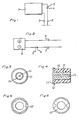
- Fig. 1 shows part of a heating system in which the heat transfer medium is water
- Fig. 2 shows part of a heating medium system
- Figs. 3 and 4 are respectively an end view and a longitudinal section of a throttling means according to the invention
- Figs. 5 and 6 show alternative embodiments of the outer sleeve of the throttling means.
- the part of the heating system shown in Fig. 1 comprises a radiator 1 having a supply conduit 2 and a return conduit 3.
- a radiator valve 4 is mounted in the supply conduit, and a fixed throttling means 5 according to the present invention is mounted on the radiator side of this valve 4. More particularly, the throttling means 5 is mounted in a coupling member of the supply conduit, including the usual elbows.
- Fig. 2 illustrates the mounting of the fixed throttling means according to the invention in a heating medium system.
- a part of this system includes a heating medium battery 6 having a supply conduit 7 and a return conduit 8.
- a shut-off valve 9 is mounted in the supply conduit, and a fixed throttling means 5 according to the invention is mounted on the battery side of the said valve 9.
- the fixed throttling means is concealed in a coupling member of the supply conduits 2 and 7, respectively, in that it is insertable coaxially therein so that it is inaccessible to unauthorized persons.
- the throttling means comprises an outer sleeve 10 of resilient material, preferably rubber, and an inner, rigid sleeve 11, preferably of brass.
- the two sleeves 10 and 11 are essentially cylindrical and are provided each with one end flange 12 and 13, respectively.
- the outer sleeve 10 has an external shape corresponding to the internal shape of the coupling member in which the throttling means is mounted.
- Alternative embodiments of the outer sleeve 10 to adapt it to difference cross-sectional shapes of the coupling members and elbows available on the market are shown in Figs. 5 and 6.
- the outer sleeve 10 has a throughpassage for receiving the inner sleeve 11 which has a central hole 14 having an exactly defined flow-controlling cross-sectional area.
- the hole 14 has the same diameter along its entire length and a sharp edge at the transition to the end surface at the flange 13.
- the end surface preferably is planar, at least adjacent the hole 14, the length of which is large in relation to the diameter. A length of the order 10 mm and greater has been found to be practically useful.
- the special design of the hole 14 guarantees an almost completely silent throttling, also at pressure drops as high as 6-8 meters of water column.
- the throughpassage of the outer sleeve 10 has, independently of the external shape of the sleeve, the same cross-sectional area throughout its length.
- the exterior shape of the inner sleeve 11 is the same and corresponds to the passage shape of the outer sleeve 10, independently of the size of the precision-drilled hole 14 in the inner sleeve 11.
- the central hole 14 of the inner sleeve 11 preferably has a cross-sectional area of a value selected from a group of predetermined values. This value is established depending on the desired temperature drop of the heating medium across the radiator, and the pressure available.
- the inner sleeve may be designed with a selected number of different ky values in the range 0.02-3.00.
- the number of different details required for the apparatus according to the present invention will thus be equal to the sum of the different types of cross-sectional shapes of the coupling members available on the market and the desired number of different cross-sectional areas of the hole 14.
- the throttling means may be mounted on the side of the control or shut-off valve facing away from the radiator, but this variant is not preferred.
- the throttling means may be mounted in the outlet or return conduit, but this usually increases the risk of blocking.
Landscapes
- Engineering & Computer Science (AREA)
- Physics & Mathematics (AREA)
- Thermal Sciences (AREA)
- Chemical & Material Sciences (AREA)
- Combustion & Propulsion (AREA)
- Mechanical Engineering (AREA)
- General Engineering & Computer Science (AREA)
- Steam Or Hot-Water Central Heating Systems (AREA)
- Sliding Valves (AREA)
Priority Applications (1)
| Application Number | Priority Date | Filing Date | Title |
|---|---|---|---|
| AT83901747T ATE29776T1 (de) | 1982-06-01 | 1983-05-26 | Heizungsanlage fuer ein haus. |
Applications Claiming Priority (2)
| Application Number | Priority Date | Filing Date | Title |
|---|---|---|---|
| SE8203360 | 1982-06-01 | ||
| SE8203360A SE435318B (sv) | 1982-06-01 | 1982-06-01 | Ljuddempande strypnippel for verme/kylsystem |
Publications (2)
| Publication Number | Publication Date |
|---|---|
| EP0125239A1 EP0125239A1 (en) | 1984-11-21 |
| EP0125239B1 true EP0125239B1 (en) | 1987-09-16 |
Family
ID=20346933
Family Applications (1)
| Application Number | Title | Priority Date | Filing Date |
|---|---|---|---|
| EP83901747A Expired EP0125239B1 (en) | 1982-06-01 | 1983-05-26 | A house heating system |
Country Status (6)
| Country | Link |
|---|---|
| EP (1) | EP0125239B1 (da) |
| DE (1) | DE3373701D1 (da) |
| DK (1) | DK153103C (da) |
| FI (1) | FI73305C (da) |
| SE (1) | SE435318B (da) |
| WO (1) | WO1983004297A1 (da) |
Cited By (1)
| Publication number | Priority date | Publication date | Assignee | Title |
|---|---|---|---|---|
| US10429864B2 (en) | 2017-05-19 | 2019-10-01 | Qsec Ab | Method for adjusting a climate system |
Families Citing this family (3)
| Publication number | Priority date | Publication date | Assignee | Title |
|---|---|---|---|---|
| FR2584171A1 (fr) * | 1985-06-26 | 1987-01-02 | Benhaim Alain | Dispositif limitateur de debit de circulation d'un fluide caloporteur pour radiateur de chauffage central et son procede de mise en oeuvre |
| SE508568C2 (sv) * | 1997-03-03 | 1998-10-19 | Mikael Lundberg | Strypdon |
| FR2812076B1 (fr) * | 2000-07-20 | 2006-01-27 | Manuli Auto France | Dispositif detendeur pour fluide frigorigene et circuit de conditionnement comprenant un tel dispositif |
Family Cites Families (14)
| Publication number | Priority date | Publication date | Assignee | Title |
|---|---|---|---|---|
| US752175A (en) * | 1904-02-16 | Mute for water-pipes | ||
| DE158823C (da) * | 1904-01-12 | |||
| US1055318A (en) * | 1911-12-01 | 1913-03-11 | Alvin C Casavant | Pipe-fitting. |
| US1493409A (en) * | 1922-01-31 | 1924-05-06 | Simplex Heating Specialty Comp | Steam-radiator valve |
| US1942783A (en) * | 1931-02-21 | 1934-01-09 | Webster Tallmadge & Company In | Orifice disk for steam radiators |
| US2244311A (en) * | 1939-05-08 | 1941-06-03 | Raymond M Nee | Flow restrictor |
| US2249469A (en) * | 1940-10-04 | 1941-07-15 | Mueller Brass Co | Orifice element for joints |
| US2676470A (en) * | 1950-04-24 | 1954-04-27 | Alquin J Streitz | Flow regulator in a refrigerating system |
| US2834379A (en) * | 1956-08-21 | 1958-05-13 | Scovill Manufacturing Co | Fluid flow control unit |
| US2933905A (en) * | 1957-07-09 | 1960-04-26 | Gen Motors Corp | Refrigerating apparatus |
| SE334724B (da) * | 1968-07-04 | 1971-05-03 | P Andersson | |
| US3517700A (en) * | 1968-12-23 | 1970-06-30 | Tydeman Machine Works Inc | Compensating element for hydrostatic bearings |
| US3820571A (en) * | 1971-11-11 | 1974-06-28 | Fischer & Porter Co | Fluid restriction assembly |
| DE2526581C3 (de) * | 1975-06-13 | 1981-09-24 | Benteler-Werke Ag Werk Neuhaus, 4790 Paderborn | Stauscheibe zum Einbau in das untere Verteilerrohr eines Heizkörpers |
-
1982
- 1982-06-01 SE SE8203360A patent/SE435318B/sv not_active IP Right Cessation
-
1983
- 1983-05-26 DE DE8383901747T patent/DE3373701D1/de not_active Expired
- 1983-05-26 EP EP83901747A patent/EP0125239B1/en not_active Expired
- 1983-05-26 WO PCT/SE1983/000208 patent/WO1983004297A1/en not_active Ceased
-
1984
- 1984-01-31 DK DK043684A patent/DK153103C/da not_active IP Right Cessation
- 1984-06-28 FI FI842619A patent/FI73305C/fi not_active IP Right Cessation
Cited By (1)
| Publication number | Priority date | Publication date | Assignee | Title |
|---|---|---|---|---|
| US10429864B2 (en) | 2017-05-19 | 2019-10-01 | Qsec Ab | Method for adjusting a climate system |
Also Published As
| Publication number | Publication date |
|---|---|
| DE3373701D1 (en) | 1987-10-22 |
| DK43684D0 (da) | 1984-01-31 |
| FI73305B (fi) | 1987-05-29 |
| FI842619A0 (fi) | 1984-06-28 |
| DK153103B (da) | 1988-06-13 |
| DK43684A (da) | 1984-01-31 |
| FI842619L (fi) | 1984-06-28 |
| SE435318B (sv) | 1984-09-17 |
| WO1983004297A1 (en) | 1983-12-08 |
| DK153103C (da) | 1988-10-31 |
| SE8203360L (sv) | 1983-12-02 |
| FI73305C (fi) | 1987-09-10 |
| EP0125239A1 (en) | 1984-11-21 |
Similar Documents
| Publication | Publication Date | Title |
|---|---|---|
| EP0993584B1 (en) | Distribution header for potable water and hot water space heating | |
| US4346731A (en) | Buoyant element check valve for a thermosiphon energy system | |
| US5950575A (en) | Hydronic manifold | |
| CN1746570B (zh) | 循环加热供暖系统的整体设备及供热方法 | |
| CN1161565C (zh) | 自动平衡液体热传递系统的装置 | |
| US5860591A (en) | Valve for a system having an energy-carrying medium | |
| US4314547A (en) | Solar hot water system with sub-loop hydronic heating | |
| EP0125239B1 (en) | A house heating system | |
| EP0568122A2 (en) | A valve assembly for plants providing both heating and domestic hot water | |
| PL216199B1 (pl) | Wielosegmentowy grzejnik wyposażony w co najmniej dwa różne segmenty grzejne | |
| US2375870A (en) | Control system | |
| GB2242247A (en) | A telescopic pipe coupling device | |
| EP0693658A1 (en) | An improved valve assembly for plants providing both heating and domestic hot water | |
| US6907905B2 (en) | Manifold of a plastics material for hot-water heating system and the like | |
| CA1264267A (en) | Arrangement in heating/cooling systems for flow adjustment | |
| EP0783642B1 (en) | Valve for a system having a heat-carrying medium | |
| US2626755A (en) | Heating system with outdoor control | |
| KR200417942Y1 (ko) | 구별 분리형 온수분배기 | |
| EP0533454A1 (en) | Heat radiators | |
| KR100727019B1 (ko) | 구별 분리형 온수분배기 | |
| US20250043961A1 (en) | Modular Hydronic Heating System Core | |
| RU2272224C2 (ru) | Отопительный конвектор | |
| RU195496U1 (ru) | Радиатор отопления с нижним подключением со встроенным термостатическим клапаном | |
| GR1003325B (el) | Συστηματα συνδεσεως θερμαντικων σωματων | |
| US4498623A (en) | Hot water heating system |
Legal Events
| Date | Code | Title | Description |
|---|---|---|---|
| PUAI | Public reference made under article 153(3) epc to a published international application that has entered the european phase |
Free format text: ORIGINAL CODE: 0009012 |
|
| 17P | Request for examination filed |
Effective date: 19840621 |
|
| AK | Designated contracting states |
Designated state(s): AT BE CH DE FR GB LI LU NL |
|
| GRAA | (expected) grant |
Free format text: ORIGINAL CODE: 0009210 |
|
| AK | Designated contracting states |
Kind code of ref document: B1 Designated state(s): AT BE CH DE FR GB LI LU NL |
|
| REF | Corresponds to: |
Ref document number: 29776 Country of ref document: AT Date of ref document: 19871015 Kind code of ref document: T |
|
| REF | Corresponds to: |
Ref document number: 3373701 Country of ref document: DE Date of ref document: 19871022 |
|
| ET | Fr: translation filed | ||
| PLBE | No opposition filed within time limit |
Free format text: ORIGINAL CODE: 0009261 |
|
| STAA | Information on the status of an ep patent application or granted ep patent |
Free format text: STATUS: NO OPPOSITION FILED WITHIN TIME LIMIT |
|
| 26N | No opposition filed | ||
| EPTA | Lu: last paid annual fee | ||
| PGFP | Annual fee paid to national office [announced via postgrant information from national office to epo] |
Ref country code: LU Payment date: 19980508 Year of fee payment: 16 Ref country code: AT Payment date: 19980508 Year of fee payment: 16 |
|
| PGFP | Annual fee paid to national office [announced via postgrant information from national office to epo] |
Ref country code: NL Payment date: 19980527 Year of fee payment: 16 |
|
| PGFP | Annual fee paid to national office [announced via postgrant information from national office to epo] |
Ref country code: BE Payment date: 19980615 Year of fee payment: 16 |
|
| PGFP | Annual fee paid to national office [announced via postgrant information from national office to epo] |
Ref country code: CH Payment date: 19980810 Year of fee payment: 16 |
|
| PG25 | Lapsed in a contracting state [announced via postgrant information from national office to epo] |
Ref country code: LU Free format text: LAPSE BECAUSE OF NON-PAYMENT OF DUE FEES Effective date: 19990526 Ref country code: AT Free format text: LAPSE BECAUSE OF NON-PAYMENT OF DUE FEES Effective date: 19990526 |
|
| PG25 | Lapsed in a contracting state [announced via postgrant information from national office to epo] |
Ref country code: LI Free format text: LAPSE BECAUSE OF NON-PAYMENT OF DUE FEES Effective date: 19990531 Ref country code: CH Free format text: LAPSE BECAUSE OF NON-PAYMENT OF DUE FEES Effective date: 19990531 Ref country code: BE Free format text: LAPSE BECAUSE OF NON-PAYMENT OF DUE FEES Effective date: 19990531 |
|
| BERE | Be: lapsed |
Owner name: HANDELSBOLAGET E.B. VARMEINREGLERING Effective date: 19990531 |
|
| PG25 | Lapsed in a contracting state [announced via postgrant information from national office to epo] |
Ref country code: NL Free format text: LAPSE BECAUSE OF NON-PAYMENT OF DUE FEES Effective date: 19991201 |
|
| REG | Reference to a national code |
Ref country code: CH Ref legal event code: PL |
|
| NLV4 | Nl: lapsed or anulled due to non-payment of the annual fee |
Effective date: 19991201 |
|
| PGFP | Annual fee paid to national office [announced via postgrant information from national office to epo] |
Ref country code: GB Payment date: 20000502 Year of fee payment: 18 |
|
| PGFP | Annual fee paid to national office [announced via postgrant information from national office to epo] |
Ref country code: DE Payment date: 20000518 Year of fee payment: 18 |
|
| PGFP | Annual fee paid to national office [announced via postgrant information from national office to epo] |
Ref country code: FR Payment date: 20000525 Year of fee payment: 18 |
|
| PG25 | Lapsed in a contracting state [announced via postgrant information from national office to epo] |
Ref country code: GB Free format text: LAPSE BECAUSE OF NON-PAYMENT OF DUE FEES Effective date: 20010526 |
|
| GBPC | Gb: european patent ceased through non-payment of renewal fee |
Effective date: 20010526 |
|
| PG25 | Lapsed in a contracting state [announced via postgrant information from national office to epo] |
Ref country code: FR Free format text: LAPSE BECAUSE OF NON-PAYMENT OF DUE FEES Effective date: 20020131 |
|
| PG25 | Lapsed in a contracting state [announced via postgrant information from national office to epo] |
Ref country code: DE Free format text: LAPSE BECAUSE OF NON-PAYMENT OF DUE FEES Effective date: 20020301 |