EP0124262A1 - Molten carbonate fuel cell - Google Patents
Molten carbonate fuel cell Download PDFInfo
- Publication number
- EP0124262A1 EP0124262A1 EP84302119A EP84302119A EP0124262A1 EP 0124262 A1 EP0124262 A1 EP 0124262A1 EP 84302119 A EP84302119 A EP 84302119A EP 84302119 A EP84302119 A EP 84302119A EP 0124262 A1 EP0124262 A1 EP 0124262A1
- Authority
- EP
- European Patent Office
- Prior art keywords
- layer
- porous
- anode
- cathode
- molten carbonate
- Prior art date
- Legal status (The legal status is an assumption and is not a legal conclusion. Google has not performed a legal analysis and makes no representation as to the accuracy of the status listed.)
- Granted
Links
- BVKZGUZCCUSVTD-UHFFFAOYSA-L Carbonate Chemical compound [O-]C([O-])=O BVKZGUZCCUSVTD-UHFFFAOYSA-L 0.000 title claims abstract description 63
- 239000000446 fuel Substances 0.000 title claims abstract description 38
- 239000011148 porous material Substances 0.000 claims abstract description 54
- 239000003792 electrolyte Substances 0.000 claims abstract description 46
- 230000009471 action Effects 0.000 claims abstract description 17
- 230000001590 oxidative effect Effects 0.000 claims abstract description 17
- 239000007800 oxidant agent Substances 0.000 claims abstract description 16
- 239000002657 fibrous material Substances 0.000 claims abstract description 14
- 239000007789 gas Substances 0.000 claims description 50
- PXHVJJICTQNCMI-UHFFFAOYSA-N Nickel Chemical compound [Ni] PXHVJJICTQNCMI-UHFFFAOYSA-N 0.000 claims description 28
- 239000000463 material Substances 0.000 claims description 18
- 239000002737 fuel gas Substances 0.000 claims description 9
- 229910000990 Ni alloy Inorganic materials 0.000 claims description 4
- 229910052759 nickel Inorganic materials 0.000 claims description 4
- 239000010410 layer Substances 0.000 description 99
- 229910052751 metal Inorganic materials 0.000 description 16
- 239000002184 metal Substances 0.000 description 16
- 238000006243 chemical reaction Methods 0.000 description 15
- 239000011651 chromium Substances 0.000 description 9
- 239000000843 powder Substances 0.000 description 9
- 239000011230 binding agent Substances 0.000 description 5
- 230000006835 compression Effects 0.000 description 5
- 238000007906 compression Methods 0.000 description 5
- 238000009792 diffusion process Methods 0.000 description 5
- 238000005245 sintering Methods 0.000 description 5
- UFHFLCQGNIYNRP-UHFFFAOYSA-N Hydrogen Chemical compound [H][H] UFHFLCQGNIYNRP-UHFFFAOYSA-N 0.000 description 4
- 239000000919 ceramic Substances 0.000 description 4
- 229910000480 nickel oxide Inorganic materials 0.000 description 4
- 229910000008 nickel(II) carbonate Inorganic materials 0.000 description 4
- 230000002459 sustained effect Effects 0.000 description 4
- 229910045601 alloy Inorganic materials 0.000 description 3
- 239000000956 alloy Substances 0.000 description 3
- 239000001257 hydrogen Substances 0.000 description 3
- 229910052739 hydrogen Inorganic materials 0.000 description 3
- 150000002739 metals Chemical class 0.000 description 3
- 229910000623 nickel–chromium alloy Inorganic materials 0.000 description 3
- 239000012466 permeate Substances 0.000 description 3
- 239000002002 slurry Substances 0.000 description 3
- CURLTUGMZLYLDI-UHFFFAOYSA-N Carbon dioxide Chemical compound O=C=O CURLTUGMZLYLDI-UHFFFAOYSA-N 0.000 description 2
- WHXSMMKQMYFTQS-UHFFFAOYSA-N Lithium Chemical compound [Li] WHXSMMKQMYFTQS-UHFFFAOYSA-N 0.000 description 2
- NBIIXXVUZAFLBC-UHFFFAOYSA-N Phosphoric acid Chemical compound OP(O)(O)=O NBIIXXVUZAFLBC-UHFFFAOYSA-N 0.000 description 2
- QVGXLLKOCUKJST-UHFFFAOYSA-N atomic oxygen Chemical compound [O] QVGXLLKOCUKJST-UHFFFAOYSA-N 0.000 description 2
- 235000011089 carbon dioxide Nutrition 0.000 description 2
- 229910052804 chromium Inorganic materials 0.000 description 2
- 238000001816 cooling Methods 0.000 description 2
- 230000001186 cumulative effect Effects 0.000 description 2
- 230000003247 decreasing effect Effects 0.000 description 2
- 238000010438 heat treatment Methods 0.000 description 2
- 238000007731 hot pressing Methods 0.000 description 2
- 230000006872 improvement Effects 0.000 description 2
- 229910052744 lithium Inorganic materials 0.000 description 2
- 238000000034 method Methods 0.000 description 2
- 239000000203 mixture Substances 0.000 description 2
- GNRSAWUEBMWBQH-UHFFFAOYSA-N oxonickel Chemical compound [Ni]=O GNRSAWUEBMWBQH-UHFFFAOYSA-N 0.000 description 2
- 239000001301 oxygen Substances 0.000 description 2
- 229910052760 oxygen Inorganic materials 0.000 description 2
- 239000002245 particle Substances 0.000 description 2
- 230000002035 prolonged effect Effects 0.000 description 2
- 239000012495 reaction gas Substances 0.000 description 2
- 239000002344 surface layer Substances 0.000 description 2
- UGFAIRIUMAVXCW-UHFFFAOYSA-N Carbon monoxide Chemical class [O+]#[C-] UGFAIRIUMAVXCW-UHFFFAOYSA-N 0.000 description 1
- VYZAMTAEIAYCRO-UHFFFAOYSA-N Chromium Chemical compound [Cr] VYZAMTAEIAYCRO-UHFFFAOYSA-N 0.000 description 1
- 229910000531 Co alloy Inorganic materials 0.000 description 1
- 229910017709 Ni Co Inorganic materials 0.000 description 1
- 229910003267 Ni-Co Inorganic materials 0.000 description 1
- 229910003262 Ni‐Co Inorganic materials 0.000 description 1
- 229910018487 Ni—Cr Inorganic materials 0.000 description 1
- NPXOKRUENSOPAO-UHFFFAOYSA-N Raney nickel Chemical compound [Al].[Ni] NPXOKRUENSOPAO-UHFFFAOYSA-N 0.000 description 1
- RTAQQCXQSZGOHL-UHFFFAOYSA-N Titanium Chemical compound [Ti] RTAQQCXQSZGOHL-UHFFFAOYSA-N 0.000 description 1
- NRTOMJZYCJJWKI-UHFFFAOYSA-N Titanium nitride Chemical compound [Ti]#N NRTOMJZYCJJWKI-UHFFFAOYSA-N 0.000 description 1
- QXZUUHYBWMWJHK-UHFFFAOYSA-N [Co].[Ni] Chemical compound [Co].[Ni] QXZUUHYBWMWJHK-UHFFFAOYSA-N 0.000 description 1
- 230000005856 abnormality Effects 0.000 description 1
- 229910052782 aluminium Inorganic materials 0.000 description 1
- XAGFODPZIPBFFR-UHFFFAOYSA-N aluminium Chemical compound [Al] XAGFODPZIPBFFR-UHFFFAOYSA-N 0.000 description 1
- 229910000147 aluminium phosphate Inorganic materials 0.000 description 1
- 229910002091 carbon monoxide Inorganic materials 0.000 description 1
- 239000003054 catalyst Substances 0.000 description 1
- 239000007795 chemical reaction product Substances 0.000 description 1
- 238000005229 chemical vapour deposition Methods 0.000 description 1
- 239000000788 chromium alloy Substances 0.000 description 1
- SZMZREIADCOWQA-UHFFFAOYSA-N chromium cobalt nickel Chemical compound [Cr].[Co].[Ni] SZMZREIADCOWQA-UHFFFAOYSA-N 0.000 description 1
- 229910017052 cobalt Inorganic materials 0.000 description 1
- 239000010941 cobalt Substances 0.000 description 1
- GUTLYIVDDKVIGB-UHFFFAOYSA-N cobalt atom Chemical compound [Co] GUTLYIVDDKVIGB-UHFFFAOYSA-N 0.000 description 1
- 239000000470 constituent Substances 0.000 description 1
- 230000001419 dependent effect Effects 0.000 description 1
- 239000002612 dispersion medium Substances 0.000 description 1
- 230000000694 effects Effects 0.000 description 1
- 238000003487 electrochemical reaction Methods 0.000 description 1
- 239000000835 fiber Substances 0.000 description 1
- XLYOFNOQVPJJNP-UHFFFAOYSA-M hydroxide Chemical compound [OH-] XLYOFNOQVPJJNP-UHFFFAOYSA-M 0.000 description 1
- YQNQTEBHHUSESQ-UHFFFAOYSA-N lithium aluminate Chemical compound [Li+].[O-][Al]=O YQNQTEBHHUSESQ-UHFFFAOYSA-N 0.000 description 1
- 230000007246 mechanism Effects 0.000 description 1
- 229920000609 methyl cellulose Polymers 0.000 description 1
- 239000001923 methylcellulose Substances 0.000 description 1
- 235000010981 methylcellulose Nutrition 0.000 description 1
- 229910021508 nickel(II) hydroxide Inorganic materials 0.000 description 1
- ZULUUIKRFGGGTL-UHFFFAOYSA-L nickel(ii) carbonate Chemical compound [Ni+2].[O-]C([O-])=O ZULUUIKRFGGGTL-UHFFFAOYSA-L 0.000 description 1
- 229910000510 noble metal Inorganic materials 0.000 description 1
- 230000002093 peripheral effect Effects 0.000 description 1
- 238000007747 plating Methods 0.000 description 1
- 230000008569 process Effects 0.000 description 1
- 230000009467 reduction Effects 0.000 description 1
- 239000007784 solid electrolyte Substances 0.000 description 1
- 238000004544 sputter deposition Methods 0.000 description 1
- 239000010935 stainless steel Substances 0.000 description 1
- 229910001220 stainless steel Inorganic materials 0.000 description 1
- VEALVRVVWBQVSL-UHFFFAOYSA-N strontium titanate Chemical compound [Sr+2].[O-][Ti]([O-])=O VEALVRVVWBQVSL-UHFFFAOYSA-N 0.000 description 1
- MTPVUVINMAGMJL-UHFFFAOYSA-N trimethyl(1,1,2,2,2-pentafluoroethyl)silane Chemical compound C[Si](C)(C)C(F)(F)C(F)(F)F MTPVUVINMAGMJL-UHFFFAOYSA-N 0.000 description 1
- 239000002699 waste material Substances 0.000 description 1
- XLYOFNOQVPJJNP-UHFFFAOYSA-N water Substances O XLYOFNOQVPJJNP-UHFFFAOYSA-N 0.000 description 1
Images


Classifications
-
- H—ELECTRICITY
- H01—ELECTRIC ELEMENTS
- H01M—PROCESSES OR MEANS, e.g. BATTERIES, FOR THE DIRECT CONVERSION OF CHEMICAL ENERGY INTO ELECTRICAL ENERGY
- H01M8/00—Fuel cells; Manufacture thereof
- H01M8/02—Details
- H01M8/0202—Collectors; Separators, e.g. bipolar separators; Interconnectors
- H01M8/023—Porous and characterised by the material
- H01M8/0232—Metals or alloys
-
- H—ELECTRICITY
- H01—ELECTRIC ELEMENTS
- H01M—PROCESSES OR MEANS, e.g. BATTERIES, FOR THE DIRECT CONVERSION OF CHEMICAL ENERGY INTO ELECTRICAL ENERGY
- H01M4/00—Electrodes
- H01M4/86—Inert electrodes with catalytic activity, e.g. for fuel cells
- H01M4/8605—Porous electrodes
- H01M4/8621—Porous electrodes containing only metallic or ceramic material, e.g. made by sintering or sputtering
-
- H—ELECTRICITY
- H01—ELECTRIC ELEMENTS
- H01M—PROCESSES OR MEANS, e.g. BATTERIES, FOR THE DIRECT CONVERSION OF CHEMICAL ENERGY INTO ELECTRICAL ENERGY
- H01M4/00—Electrodes
- H01M4/86—Inert electrodes with catalytic activity, e.g. for fuel cells
- H01M4/90—Selection of catalytic material
- H01M4/9041—Metals or alloys
-
- H—ELECTRICITY
- H01—ELECTRIC ELEMENTS
- H01M—PROCESSES OR MEANS, e.g. BATTERIES, FOR THE DIRECT CONVERSION OF CHEMICAL ENERGY INTO ELECTRICAL ENERGY
- H01M8/00—Fuel cells; Manufacture thereof
- H01M8/14—Fuel cells with fused electrolytes
- H01M8/141—Fuel cells with fused electrolytes the anode and the cathode being gas-permeable electrodes or electrode layers
- H01M8/142—Fuel cells with fused electrolytes the anode and the cathode being gas-permeable electrodes or electrode layers with matrix-supported or semi-solid matrix-reinforced electrolyte
-
- H—ELECTRICITY
- H01—ELECTRIC ELEMENTS
- H01M—PROCESSES OR MEANS, e.g. BATTERIES, FOR THE DIRECT CONVERSION OF CHEMICAL ENERGY INTO ELECTRICAL ENERGY
- H01M8/00—Fuel cells; Manufacture thereof
- H01M8/14—Fuel cells with fused electrolytes
- H01M2008/147—Fuel cells with molten carbonates
-
- H—ELECTRICITY
- H01—ELECTRIC ELEMENTS
- H01M—PROCESSES OR MEANS, e.g. BATTERIES, FOR THE DIRECT CONVERSION OF CHEMICAL ENERGY INTO ELECTRICAL ENERGY
- H01M2300/00—Electrolytes
- H01M2300/0017—Non-aqueous electrolytes
- H01M2300/0048—Molten electrolytes used at high temperature
- H01M2300/0051—Carbonates
-
- H—ELECTRICITY
- H01—ELECTRIC ELEMENTS
- H01M—PROCESSES OR MEANS, e.g. BATTERIES, FOR THE DIRECT CONVERSION OF CHEMICAL ENERGY INTO ELECTRICAL ENERGY
- H01M4/00—Electrodes
- H01M4/86—Inert electrodes with catalytic activity, e.g. for fuel cells
- H01M4/8647—Inert electrodes with catalytic activity, e.g. for fuel cells consisting of more than one material, e.g. consisting of composites
-
- Y—GENERAL TAGGING OF NEW TECHNOLOGICAL DEVELOPMENTS; GENERAL TAGGING OF CROSS-SECTIONAL TECHNOLOGIES SPANNING OVER SEVERAL SECTIONS OF THE IPC; TECHNICAL SUBJECTS COVERED BY FORMER USPC CROSS-REFERENCE ART COLLECTIONS [XRACs] AND DIGESTS
- Y02—TECHNOLOGIES OR APPLICATIONS FOR MITIGATION OR ADAPTATION AGAINST CLIMATE CHANGE
- Y02E—REDUCTION OF GREENHOUSE GAS [GHG] EMISSIONS, RELATED TO ENERGY GENERATION, TRANSMISSION OR DISTRIBUTION
- Y02E60/00—Enabling technologies; Technologies with a potential or indirect contribution to GHG emissions mitigation
- Y02E60/30—Hydrogen technology
- Y02E60/50—Fuel cells
Definitions
- the present invention relates to a molten carbonate fuel cell and, more particularly, to a molten carbonate fuel cell wherein an anode and a cathode are formed in contact with an electrolyte layer containing a carbonate and are porous layers, and the supply of reactive gas and the discharge of reaction products are performed through small pores in these electrodes.
- Fuel cells are roughly classified based on the type of electrolyte used in fuel cells of phosphoric acid, molten carbonate, and solid electrolyte type. Of these types, molten carbonate fuel cells are operated at a temperature around 650°C. Molten carbonate fuel cells do not require the use of a noble metal as catalyst, allow the use of carbon monoxides in place of hydrogen as fuel, have a relatively high voltage generated per unit cell, and allow utilization of high-temperature waste energy.
- Such a molten carbonate fuel cell generally consists of a plurality of stacked unit cells. Output voltage from each unit cell is at best about 1 V. Thus, in order to obtain a practical cell, a plurality of such unit cells must be electrically connected in a series.
- Each unit cell of such a molten carbonate fuel cell generally comprises an electrolyte layer in a plate-like form containing: a carbonate, melted at operating temperature; a cathode and an anode, which are formed in tight contact to sandwich the electrolyte layer and which comprise plates of porous material; an element for supplying fuel gas to the interface between the cathode and the electrolyte layer through pores in the cathode; and another element for supplying an oxidant gas to the interface between the anode and the electrolyte layer through pores in the anode.
- the elements for supplying the fuel and oxidant gases comprise a plurality of gas guide grooves, defined between those surfaces of conductive interconnectors inserted between each adjacent unit cells and which contact the unit cells when such unit cells are stacked.
- Gas guide grooves for guiding the fuel gas and those for guiding the oxidant gas are formed perpendicularly to each other, so as to allow each connection access to sources of the respective gases.
- the fuel gas guided by such gas guide grooves is diffused in the cathode in its direction of thickness toward the electrolyte layer.
- the oxidant gas guided through the corresponding gas guide grooves is diffused through the anode in its direction of thickness toward the electrolyte layer.
- the output characteristics are largely dependent on the structure and characteristics of the anode and cathode.
- the anode and cathode must satisfy the following requirements: the anode and cathode are chemically stable against a molten carbonate at a temperature of 600 to 700°C, have a capacity of guiding the fuel gas and oxidant gas to the reaction site through internal pores, are capable of sustaining guide paths of gases over a long period of time, of guiding the molten carbonate to the reaction site, of stably sustaining the guide path of the molten carbonate, have good electron conductivity, can reduce the contact resistance with the electrolyte layer or the interconnector, and have a large specific surface area so as to have a large number of three-phase surfaces (reaction points) where the electrodes, the reactive material, and carbonate ions are all present.
- a cathode and an anode comprise porous plates, which are obtained by sintering a nickel-based alloy powder to have a narrow pore size distribution.
- an electrode which comprises a sintered porous plate of a powdery material, wherein the average pore size is small toward the electrolyte layer and is large toward the gas supply side.
- the electrode when a powdery material is sintered to form a porous electrode, the electrode has a porous structure wherein the points of powder particles contact each other. For this reason, when the porosity is set to be 50% or more, the electron conductivity is decreased and a voltage drop between the cathode or anode is increased.
- a porous electrode of such a structure has low mechanical strength and elasticity. The electrode may be broken due to stress applied by a shrinkage difference between the electrode and electrolyte layer when the cell temperature is decreased. The contact between the electrode and the interconnector may be made non-uniform to increase the contact resistance at this portion.
- a molten carbonate fuel cell comprising unit cells each having an electrolyte layer in a plate-like form which contains a carbonate melted at an operating temperature, a cathode and an anode which are formed in tight contact to sandwich the electrolyte layer and which comprise plates of porous material, an element for supplying fuel gas to the interface between the cathode and the electrolyte layer through pores in the cathode, and another element for supplying an oxidant gas to the interface between the anode and the electrolyte layer through pores in the anode.
- each cathode and anode of the cell in this invention comprises a bilayered structure having a first porous layer formed in contact with the electrolyte layer, and a second porous layer formed at the side of the element for supplying fuel (or oxidant) gas and consisting of a sintered fibrous material.
- the pores formed in the first porous layer at least the pores near the electrolyte layer are formed to have a size allowing capillary action of the molten carbonate to pass through.
- the pores of the second porous layer are formed to have a size which does not allow capillary action to pass through.
- each cathode and anode of a unit cell has a bilayered structure of first and second porous layers.
- the first porous layer of each cathode and anode is in contact with the electrolyte layer, and the second porous layer thereof is in contact with the gas supply element, that is, the interconnector.
- the second porous layer comprises a sintered layer of a fibrous material. Since a porous body, obtained by sintering an electrically conductive fibrous material, has a large contact area between fibers, it has an extremely high electron conductivity as compared to a porous body obtained by sintering a powdery material. Thus, the voltage drop between the cathode or anode can be reduced.
- a porous body obtained by sintering a fibrous material has high mechanical strength in the lateral direction and good elasticity.
- a cathode or anode comprises such a porous body, its mechanical strength can be improved and the contact resistance with the interconnector can be significantly reduced.
- the voltage drop between the electrodes or between the electrode and the interconnector can be reduced.
- damage to the electrodes generally caused by a difference in shrinkage between the electrodes and the electrolyte when the temperature of the cell is lowered, can be prevented.
- the electrolyte can be sustained over a long period of time, and the output density can be improved.
- the molten carbonate permeates into the first porous layer and tends to move toward the second porous layer in both the cathode and anode.
- the second porous layer does not allow capillary action.
- the pores of the second porous layer are in contact with the supply source of the reactive gas.
- the permeated carbonate only permeates to a position where the permeating power of the carbonate by capillary action balances the gas pressure acting through the pores of the second porous layer.
- the permeated carbonate is then stabilized. No compression force acts on the molten carbonate in the electrolyte layer, and no force acts to transfer the molten carbonate into the path of the reactive gas through the pores of the cathode and anode.
- the molten carbonate is therefore stably sustained over a long period of time, and the cell life is prolonged.
- the second porous layer Since the second porous layer has a large pore size, it contributes to decrease the diffusion resistance of the reactive gas. Meanwhile, since the first porous layer has a small pore size and has the molten carbonate permeated therein, it contributes to increase the number of reaction points, that is, a specific surface area. Thus, the output density is improved.
- Fig. 1 shows a main section 10 of a molten carbonate fuel cell of the present invention.
- the main section 10 comprises a stacked body consisting of a plurality of unit cells 11 with an interconnector 12 inserted between each pair of unit cells 11.
- Each unit cell 11 consists of an electrolyte layer 13 of a plate-like shape, a cathode 14 and an anode 15 of plate-like shape formed in,contact,with the surfaces of the electrolyte later 13, and a plurality of gas guide grooves 16 and 17, formed in the surfaces of the interconnector 12, which contact with the cathode 14 and the anode 15, respectively.
- the electrolyte layer 13 comprises a plate having a thickness of, for example, 2 mm and formed by hot pressing at 450°C a mixture consisting of, for example, .. 60% by weight of a carbonate and 40% by weight of a ceramic-type binder.
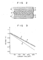
- the cathode 14 and anode 15 comprise porous bodies having a thickness of, for example, 1 mm. More specifically, each of the cathode 14 and anode 15 comprises a bilayered structure having a first porous layer 18, formed at the side of the electrolyte layer 13, and a second porous layer 19, formed at the opposite side, as shown in Fig. 2.
- the first porous layer 18 comprises a sintered body of a fibrous or powdery nickel or nickel-chromium alloy.
- the first porous layer 18 has a pore size to allow capillary action of the molten carbonate, such as a pore size of 0.3 to 20 um, a porosity of 60 to 80%, and a thickness of 0.3 mm.
- the second porous layer 19 comprises a sintered body of a fibrous nickel or nickel-chromium alloy.
- the second porous layer 19 has a pore size not to allow capillary action of the molten carbonate, such as a pore size of 21 to 50 ⁇ m, a porosity of 60 to 80%, and a thickness of 0.7 mm.
- Each interconnector 12 consists of stainless steel which is chemically inert against the carbonate.
- the gas guide grooves 16 and 17, formed on the two surfaces of each interconnector 12, are perpendicular to each other.
- the surface portion of the interconnector 12 in which the grooves 16 or 17 are formed, is recessed at a depth corresponding to the thickness of the cathode 14 or anode 15. Therefore, when the cathode 14 or anode 15 is fitted with the corresponding surface of the interconnector 12, the surface of the cathode 14 or anode 15 in contact with the electrolyte layer 13 is coplanar with the peripheral portion of the same surface of the interconnector 12.
- the main section 10 comprising a stacked body of unit cells 11 and interconnectors 12, is fastened with a fastening mechanism (not shown) in the stacking direction.
- Manifolds (not shown) for supplying the supply gas are hermetically attached to the four sides of the stacked body.
- an electrical load is connected across the stacked body, which is heated to a temperature at which the carbonate in the electrolyte layer 13 is molten.
- an oxidant gas flows to the gas guide grooves 17 through the corresponding manifolds in the direction indicated by the thick broken arrow P shown in Fig. 1.
- fuel gas is also supplied to the gas guide grooves 16 through the corresponding manifolds in the direction indicated by thick arrow Q.
- Part of the fuel gas flowing through the gas guide grooves 16 is diffused in the pores of the cathode 14 and reaches the reaction points at which the cathode 14 and the carbonate meet.
- part of the oxidant gas, flowing through the gas guide grooves 17 is diffused in the pores of the anode 15 to reach the reaction points at which the anode 15 and the carbonate meet. The electromotive reaction is thus effected.
- each of the cathode 14 and anode 15, as the constituent elements of each unit cell 11, comprises a bilayered structure of first and second porous layers 18 and 19.
- the pore size of the first porous layer 18, located at the side of the electrolyte later 13, is set to allow capillary action of the molten carbonate.
- the pore size of the second porous layer 19, located at the opposite side is set to not allow such capillary action.
- the carbonate can be sustained for a long period of time, and the cell life can be prolonged. Since the first porous layer 18 has a small pore size and contains the molten carbonate permeated therein, the specific surface area can be increased. On the other hand, the second porous layer 19 has a large pore size and can satisfactorily reduce the diffusion resistance of the reactive gas. As a consequence, the number of reaction points can be increased, and a sufficient amount of the reaction gas can be supplied to these reaction points, so that the output density can be improved.
- the second porous layer 19 located at the side of the interconnector 12 comprises a sintered body of an electrically conductive fibrous material.
- a porous body obtained by sintering a fibrous material has a higher mechanical strength and elasticity than that of a porous material obtained by a powdery material and has a lower electrical resistance in the direction of thickness than that of the latter.
- the presence of the second porous layer 19 prevents damage of the cathode 14 and anode 15 due to the heating/cooling cycle and reduces the voltage drop between the electrodes and between the electrode and interconnector.
- a fibrous metal consisting of Ni (80) -Cr (20) having an average diameter of 25 ⁇ m and an aspect ratio of 4 or more, were charged into a former.
- the metals were formed into a plate.
- the plate was placed in an H 2(20) -N 2(80) gas atmosphere and was sintered at 850°C for 1 hour.
- a porous body of Ni (80) -Cr (20) was thus obtained.
- the porous body was microscopically observed in a section.along the direction of its thickness.
- a layer of the fibrous metal having the diameter of 25 ⁇ m had a pore size of 22 to 30 ⁇ m, which does not cause capillary action, and a porosity of 75%.
- a layer of the fibrous material having the diameter of 4 ⁇ m had a pore size of 2 to 5 ⁇ m, which easily causes capillary action, and a porosity of 75%.
- a layer of the fibrous metal having the average diameter of 30 ⁇ m (second porous layer) had a pore size of 25 to 35 ⁇ m and a porosity of 70%.
- a layer of the fibrous metal having the average diameter of 8 ⁇ m (first porous layer) had a pore size of 8 to 12 ⁇ m and a porosity of 70%.
- the ratio of the thicknesses of the first and second porous layers was about 1.0 : 3.2.
- the Ni (80) -Cr (20) porous body and the Ni porous body thus prepared separately were placed on two sides of an electrolyte layer such that the Ni (80) -Cr (20) porous body was used as a cathode and the Ni porous body was used as an anode, and each first porous layer faced the electrolyte layer.
- a fuel cell was thus assembled.
- the electrolyte layer was obtained by hot pressing at 450°C and by forming a mixture of 60% by weight of a carbonate and 40% by weight of a ceramic as a binder.
- Fig. 3 shows a current-voltage characteristic curve A of the fuel cell prepared in this manner together with that B of a fuel cell having as gas diffusion electrode porous bodies of a conventional structure.
- the cell of the present invention has better characteristics than those of the cell of a conventional structure. This fact indicates that in the cell of the present invention when the pore size in the second porous layer, located at the gas supply side, is large, the supply of the reactive gas can be performed satisfactorily.
- Fig. 4 shows changes in output voltage of the cell during operation over an extended period of time.
- Curve A corresponds to a cell of the present invention
- curve B corresponds to a cell of conventional structure.
- the fuel cell of the present invention can stably provide the electromotive reaction over a long period of time. This also indicates that the electrolyte is stably held by the cathode and anode, demonstrating that the first porous layers having a small pore size are serving their original purpose.
- the cell prepared in the manner described above was subjected to a plurality of heat cycles each comprising heating from room temperature to the operating temperature and cooling back to room temperature again.
- the cell exhibited no abnormality in the cathode and anode.
- a fibrous metal of an Ni(80)-Cr(20) alloy having a diameter of 2 to 10 ⁇ m and an aspect ratio of 4 or more, was charged in a former in a layered form of 0.5 mm thickness.
- the metals were formed by compression into a plate of 0.8 mm thickness.
- the plate was sintered in a hydrogen-containing atmosphere at 1,050°C for 1 hour to provide a bilayered porous electrode.
- the sintered layer of powdery material had a pore size of 22 to 30 ⁇ m and the sintered layer of fibrous material had a pore size of 22 to 30 ⁇ m.
- the former layer had a porosity of 75%, and the latter layer had a porosity of 70%.
- Electrodes each consisting of such sintered layers of powdery and fibrous materials were prepared.
- the electrodes were presintered in the air at 500°C to vaporize the binder and to thermally decompose the nickel carbonate into nickel oxide (NiO). Thereafter, the electrodes were sintered in hydrogen at 1,000°C for 1 hour to reduce the nickel oxide. Fine powdery layers of 0.05 to 0.2 mm thickness precipitated on the surfaces of the sintered layers of powdery material of the respective electrodes.
- electrodes were prepared each having a sintered layer of the powdery material and a fine powder layer as the first porous layer, and a sintered layer of fibrous material as the second porous layer.
- the fine powder layers of the two electrodes thus prepared had a porosity of 60 to 80% and a pore size distribution (cumulative volume fraction: 10 to 90%) of 0.3 to 1.5 ⁇ m.
- a unit cell was assembled using the two electrodes such that the fine powder layers faced the electrolyt layer, following the same procedures as in Example 1.
- the unit cell was heated from room temperature to 650°C at a rate of 50°C/h and was kept at 650°C.
- the electromotive reaction was performed with a fuel gas having a ratio of air to carbonic acid gas of 8 : 2 and an oxidant gas having a ratio of air to carbonic acid gas of 7 : 3.
- the relationship between the terminal voltage and the current density was examined.
- the results revealed the characteristics indicated by curve C in Fig. 3.
- the bubble pressure of the cell in Example 2 also presented a 15% improvement over that of the cell in Example 1.
- the cell in Example 2 had a cathode and anode with satisfactory mechanical strength and elasticity which were suitable for electrodes of a molten carbonate fuel cell.
- the powdery and fibrous materials were nickel or nickel-chromium alloys. However, they need not be limited to these materials.
- Example 2 compression is performed so as to form electrodes.
- fibrous and powdery layers can be formed into soft layers containing a binder, and these layers can then be adhered with rollers and sintered.
- Example 2 when fine powder layers were formed, a slurry of NiC0 3 with water as a dispersion medium w applied to the electrodes. Fine Ni particles were precipitated and sintered to form fine powder layers.
- the material for the above is not limited to Ni but may be any material which does not generate a corrosive gas such as Ni(OH) 2 or (CH 3 C00) 2 Ni.
- NiC0 3 or (CH 3 C00) 2 Ni can be decomposed in an oxygen atmosphere, and then a slurry containing NiO can be applied onto the surface of the sintered layers of powdery material.
- the material need not be limited to Ni alone but may be a carbonate or hydroxide containing Ni and Cr or Co. When such a material is used, it is thermally decomposed to form fine powder layers of Ni-Cr, Ni-Co or Ni-Cr-Co.
Landscapes
- Chemical & Material Sciences (AREA)
- General Chemical & Material Sciences (AREA)
- Engineering & Computer Science (AREA)
- Chemical Kinetics & Catalysis (AREA)
- Electrochemistry (AREA)
- Life Sciences & Earth Sciences (AREA)
- Manufacturing & Machinery (AREA)
- Sustainable Development (AREA)
- Sustainable Energy (AREA)
- Ceramic Engineering (AREA)
- Materials Engineering (AREA)
- Fuel Cell (AREA)
- Inert Electrodes (AREA)
Abstract
Description
- The present invention relates to a molten carbonate fuel cell and, more particularly, to a molten carbonate fuel cell wherein an anode and a cathode are formed in contact with an electrolyte layer containing a carbonate and are porous layers, and the supply of reactive gas and the discharge of reaction products are performed through small pores in these electrodes.
- When a gas which can be easily oxidized, such as hydrogen gas, and a gas which has a strong oxidizing power, such as oxygen, are reacted through an electrochemical reaction process, DC power can be generated. A fuel cell realizes such a reaction process.
- Fuel cells are roughly classified based on the type of electrolyte used in fuel cells of phosphoric acid, molten carbonate, and solid electrolyte type. Of these types, molten carbonate fuel cells are operated at a temperature around 650°C. Molten carbonate fuel cells do not require the use of a noble metal as catalyst, allow the use of carbon monoxides in place of hydrogen as fuel, have a relatively high voltage generated per unit cell, and allow utilization of high-temperature waste energy.
- Such a molten carbonate fuel cell generally consists of a plurality of stacked unit cells. Output voltage from each unit cell is at best about 1 V. Thus, in order to obtain a practical cell, a plurality of such unit cells must be electrically connected in a series.
- Each unit cell of such a molten carbonate fuel cell generally comprises an electrolyte layer in a plate-like form containing: a carbonate, melted at operating temperature; a cathode and an anode, which are formed in tight contact to sandwich the electrolyte layer and which comprise plates of porous material; an element for supplying fuel gas to the interface between the cathode and the electrolyte layer through pores in the cathode; and another element for supplying an oxidant gas to the interface between the anode and the electrolyte layer through pores in the anode. The elements for supplying the fuel and oxidant gases comprise a plurality of gas guide grooves, defined between those surfaces of conductive interconnectors inserted between each adjacent unit cells and which contact the unit cells when such unit cells are stacked. Gas guide grooves for guiding the fuel gas and those for guiding the oxidant gas are formed perpendicularly to each other, so as to allow each connection access to sources of the respective gases. The fuel gas guided by such gas guide grooves is diffused in the cathode in its direction of thickness toward the electrolyte layer. On the other hand, the oxidant gas guided through the corresponding gas guide grooves is diffused through the anode in its direction of thickness toward the electrolyte layer.
- In a molten carbonate fuel cell of the type described above, the output characteristics are largely dependent on the structure and characteristics of the anode and cathode. In order that a molten carbonate fuel cell has stable output characteristics over a long period of time, the anode and cathode must satisfy the following requirements: the anode and cathode are chemically stable against a molten carbonate at a temperature of 600 to 700°C, have a capacity of guiding the fuel gas and oxidant gas to the reaction site through internal pores, are capable of sustaining guide paths of gases over a long period of time, of guiding the molten carbonate to the reaction site, of stably sustaining the guide path of the molten carbonate, have good electron conductivity, can reduce the contact resistance with the electrolyte layer or the interconnector, and have a large specific surface area so as to have a large number of three-phase surfaces (reaction points) where the electrodes, the reactive material, and carbonate ions are all present.
- In view of these requirements, in a conventional molten carbonate fuel cell, a cathode and an anode comprise porous plates, which are obtained by sintering a nickel-based alloy powder to have a narrow pore size distribution.
- When a cathode and anode of a material having a large average pore size, for example, 20 µm or more, are used to stably supply the fuel and oxidant gases, the pressure of the supplied gas is applied to the electrolyte layer. This may reduce the number of reaction points. Then, output density cannot be improved. On .. the other hand, when a cathode and anode of a porous material having a small average pore size, for example, 2 µm or less, are used to provide a large number of reaction points, the molten carbonate is guided toward the gas guide grooves by capillary action through the electrodes. Then, in this case, the electrolyte cannot be stably sustained. Furthermore, in this case, the electrolyte which has permeated into the pores results in an increase in the diffusion resistance of the gas, so that supply of reactive gas is prevented.
- In order to solve these problems, an electrode has been proposed which comprises a sintered porous plate of a powdery material, wherein the average pore size is small toward the electrolyte layer and is large toward the gas supply side. When a cathode and anode of such a structure are assembled, pores having different sizes in the direction of thickness serve well to improve the output density and to sustain the electrolyte over a long period of time.
- However, when a powdery material is sintered to form a porous electrode, the electrode has a porous structure wherein the points of powder particles contact each other. For this reason, when the porosity is set to be 50% or more, the electron conductivity is decreased and a voltage drop between the cathode or anode is increased. In addition, a porous electrode of such a structure has low mechanical strength and elasticity. The electrode may be broken due to stress applied by a shrinkage difference between the electrode and electrolyte layer when the cell temperature is decreased. The contact between the electrode and the interconnector may be made non-uniform to increase the contact resistance at this portion.
- It is an object of the present invention to provide a molten carbonate fuel cell which can be operated at a high output density over a long period of time and which allows reduction in the internal resistance of the cell.
- In order to achieve the above object of the present invention, there is provided a molten carbonate fuel cell comprising unit cells each having an electrolyte layer in a plate-like form which contains a carbonate melted at an operating temperature, a cathode and an anode which are formed in tight contact to sandwich the electrolyte layer and which comprise plates of porous material, an element for supplying fuel gas to the interface between the cathode and the electrolyte layer through pores in the cathode, and another element for supplying an oxidant gas to the interface between the anode and the electrolyte layer through pores in the anode.
- In a molten carbonate fuel cell having such a structure, each cathode and anode of the cell in this invention comprises a bilayered structure having a first porous layer formed in contact with the electrolyte layer, and a second porous layer formed at the side of the element for supplying fuel (or oxidant) gas and consisting of a sintered fibrous material. Of the pores formed in the first porous layer, at least the pores near the electrolyte layer are formed to have a size allowing capillary action of the molten carbonate to pass through. In addition to this, the pores of the second porous layer are formed to have a size which does not allow capillary action to pass through.
- In a molten carbonate fuel cell of the present invention, each cathode and anode of a unit cell has a bilayered structure of first and second porous layers. The first porous layer of each cathode and anode is in contact with the electrolyte layer, and the second porous layer thereof is in contact with the gas supply element, that is, the interconnector. The second porous layer comprises a sintered layer of a fibrous material. Since a porous body, obtained by sintering an electrically conductive fibrous material, has a large contact area between fibers, it has an extremely high electron conductivity as compared to a porous body obtained by sintering a powdery material. Thus, the voltage drop between the cathode or anode can be reduced. A porous body obtained by sintering a fibrous material has high mechanical strength in the lateral direction and good elasticity. When a cathode or anode comprises such a porous body, its mechanical strength can be improved and the contact resistance with the interconnector can be significantly reduced. In this manner, according to the present invention, the voltage drop between the electrodes or between the electrode and the interconnector can be reduced. In addition to this, damage to the electrodes, generally caused by a difference in shrinkage between the electrodes and the electrolyte when the temperature of the cell is lowered, can be prevented. The electrolyte can be sustained over a long period of time, and the output density can be improved. In operation, the molten carbonate permeates into the first porous layer and tends to move toward the second porous layer in both the cathode and anode. However, the second porous layer does not allow capillary action. Furthermore, the pores of the second porous layer are in contact with the supply source of the reactive gas. For this reason, the permeated carbonate only permeates to a position where the permeating power of the carbonate by capillary action balances the gas pressure acting through the pores of the second porous layer. The permeated carbonate is then stabilized. No compression force acts on the molten carbonate in the electrolyte layer, and no force acts to transfer the molten carbonate into the path of the reactive gas through the pores of the cathode and anode. The molten carbonate is therefore stably sustained over a long period of time, and the cell life is prolonged.
- Since the second porous layer has a large pore size, it contributes to decrease the diffusion resistance of the reactive gas. Meanwhile, since the first porous layer has a small pore size and has the molten carbonate permeated therein, it contributes to increase the number of reaction points, that is, a specific surface area. Thus, the output density is improved.
- This invention can be more fully understood from the following detailed description when taken in conjunction with the accompanying drawings, in which:
- Fig. 1 is an exploded perspective view showing the main part of a molten carbonate fuel cell according to an embodiment of the present invention;
- Fig. 2 is a cross-sectional view of the main part of a unit cell used in the cell shown in Fig. 1;
- Fig. 3 is a graph showing output voltage-output current characteristics of a molten carbonate fuel cell of the present invention compared with those of a conventional cell; and
- Fig. 4 is a graph showing changes in output voltages against time of the molten carbonate fuel cell of the present invention together with those of the conventional cell.
- Fig. 1 shows a
main section 10 of a molten carbonate fuel cell of the present invention. Themain section 10 comprises a stacked body consisting of a plurality ofunit cells 11 with aninterconnector 12 inserted between each pair ofunit cells 11. - Each
unit cell 11 consists of anelectrolyte layer 13 of a plate-like shape, acathode 14 and ananode 15 of plate-like shape formed in,contact,with the surfaces of the electrolyte later 13, and a plurality ofgas guide grooves interconnector 12, which contact with thecathode 14 and theanode 15, respectively. - The
electrolyte layer 13 comprises a plate having a thickness of, for example, 2 mm and formed by hot pressing at 450°C a mixture consisting of, for example, .. 60% by weight of a carbonate and 40% by weight of a ceramic-type binder. - The
cathode 14 andanode 15 comprise porous bodies having a thickness of, for example, 1 mm. More specifically, each of thecathode 14 andanode 15 comprises a bilayered structure having a firstporous layer 18, formed at the side of theelectrolyte layer 13, and a secondporous layer 19, formed at the opposite side, as shown in Fig. 2. The firstporous layer 18 comprises a sintered body of a fibrous or powdery nickel or nickel-chromium alloy. The firstporous layer 18 has a pore size to allow capillary action of the molten carbonate, such as a pore size of 0.3 to 20 um, a porosity of 60 to 80%, and a thickness of 0.3 mm. The secondporous layer 19 comprises a sintered body of a fibrous nickel or nickel-chromium alloy. The secondporous layer 19 has a pore size not to allow capillary action of the molten carbonate, such as a pore size of 21 to 50 µm, a porosity of 60 to 80%, and a thickness of 0.7 mm. - Each
interconnector 12 consists of stainless steel which is chemically inert against the carbonate. Thegas guide grooves grooves cathode 14 oranode 15. Therefore, when thecathode 14 oranode 15 is fitted with the corresponding surface of theinterconnector 12, the surface of thecathode 14 oranode 15 in contact with theelectrolyte layer 13 is coplanar with the peripheral portion of the same surface of theinterconnector 12. - The
main section 10, comprising a stacked body ofunit cells 11 andinterconnectors 12, is fastened with a fastening mechanism (not shown) in the stacking direction. Manifolds (not shown) for supplying the supply gas are hermetically attached to the four sides of the stacked body. In order to cause the actual electromotive reaction, an electrical load is connected across the stacked body, which is heated to a temperature at which the carbonate in theelectrolyte layer 13 is molten. Subsequently, an oxidant gas flows to thegas guide grooves 17 through the corresponding manifolds in the direction indicated by the thick broken arrow P shown in Fig. 1. At the same time, fuel gas is also supplied to thegas guide grooves 16 through the corresponding manifolds in the direction indicated by thick arrow Q. - Part of the fuel gas flowing through the
gas guide grooves 16 is diffused in the pores of thecathode 14 and reaches the reaction points at which thecathode 14 and the carbonate meet. Likewise, part of the oxidant gas, flowing through thegas guide grooves 17, is diffused in the pores of theanode 15 to reach the reaction points at which theanode 15 and the carbonate meet. The electromotive reaction is thus effected. - In the molten carbonate fuel cell of the present invention, each of the
cathode 14 andanode 15, as the constituent elements of eachunit cell 11, comprises a bilayered structure of first and secondporous layers porous layer 18, located at the side of the electrolyte later 13, is set to allow capillary action of the molten carbonate. On the other hand, the pore size of the secondporous layer 19, located at the opposite side, is set to not allow such capillary action. Thus, the carbonate which has permeated through the firstporous layer 18 can permeate only to a position at which the permeating force of the capillary action is balanced by the gas pressure acting through the pores of the secondporous layer 19, and it is stabilized at such a position. For this reason, no compression or suction force acts on the molten carbonate in theelectrolyte layer 13. Loss of the carbonate is smaller than in the case where the carbonate is subject to such a compression or suction force. The carbonate can be sustained for a long period of time, and the cell life can be prolonged. Since the firstporous layer 18 has a small pore size and contains the molten carbonate permeated therein, the specific surface area can be increased. On the other hand, the secondporous layer 19 has a large pore size and can satisfactorily reduce the diffusion resistance of the reactive gas. As a consequence, the number of reaction points can be increased, and a sufficient amount of the reaction gas can be supplied to these reaction points, so that the output density can be improved. When the permeating power of the molten carbonate is properly set by suitably selecting the pore size of the firstporous layer 18, the bubble pressure can be improved by about 50% compared to a conventional case, and this serves to prevent intermixing of the fuel and oxidant gases. This simplifies the supply of the reaction gas and improves safety. The secondporous layer 19 located at the side of theinterconnector 12 comprises a sintered body of an electrically conductive fibrous material. A porous body obtained by sintering a fibrous material has a higher mechanical strength and elasticity than that of a porous material obtained by a powdery material and has a lower electrical resistance in the direction of thickness than that of the latter. The presence of the secondporous layer 19 prevents damage of thecathode 14 andanode 15 due to the heating/cooling cycle and reduces the voltage drop between the electrodes and between the electrode and interconnector. - The present invention will now be described by way of examples to demonstrate the effects thereof.
- Three parts of a fibrous metal consisting of Ni(80)-Cr(20), having an average diameter of 25 µm and an aspect ratio of 4 or more, were charged into a former. One part of a fibrous metal consisting of Ni(80)-Cr(20), having an average diameter of 4 µm and an aspect ratio of 4 or more, was charged onto the former metal portion. The metals were formed into a plate. The plate was placed in an H2(20)-N2(80) gas atmosphere and was sintered at 850°C for 1 hour. A porous body of Ni(80)-Cr(20) was thus obtained. The porous body was microscopically observed in a section.along the direction of its thickness. A layer of the fibrous metal having the diameter of 25 µm (second porous layer) had a pore size of 22 to 30 µm, which does not cause capillary action, and a porosity of 75%. A layer of the fibrous material having the diameter of 4 µm (first porous layer) had a pore size of 2 to 5 µm, which easily causes capillary action, and a porosity of 75%.
- Mechanical tests of the porous body revealed that the porous body had tensile strength, softness, and surface smoothness which were satisfactory for a gas diffusion electrode of a fuel cell.
- Separately, three parts of a fibrous metal Ni having an average diameter of 30 µm and one part of a fibrous metal Ni having an average diameter of 8 µm were charged into a former in a layered form. The metals were formed into a plate. The plate was sintered in an H2(20) N2(80) gas atmosphere at 820°C for 1 hour to provide an Ni porous body. The Ni porous body was microscopically observed in a section along the direction of its thickness. The following results were obtained. A layer of the fibrous metal having the average diameter of 30 µm (second porous layer) had a pore size of 25 to 35 µm and a porosity of 70%. A layer of the fibrous metal having the average diameter of 8 µm (first porous layer) had a pore size of 8 to 12 µm and a porosity of 70%. The ratio of the thicknesses of the first and second porous layers was about 1.0 : 3.2.
- The Ni(80)-Cr(20) porous body and the Ni porous body thus prepared separately were placed on two sides of an electrolyte layer such that the Ni(80)-Cr(20) porous body was used as a cathode and the Ni porous body was used as an anode, and each first porous layer faced the electrolyte layer. A fuel cell was thus assembled. The electrolyte layer was obtained by hot pressing at 450°C and by forming a mixture of 60% by weight of a carbonate and 40% by weight of a ceramic as a binder.
- Fig. 3 shows a current-voltage characteristic curve A of the fuel cell prepared in this manner together with that B of a fuel cell having as gas diffusion electrode porous bodies of a conventional structure. As can be seen from Fig. 3, the cell of the present invention has better characteristics than those of the cell of a conventional structure. This fact indicates that in the cell of the present invention when the pore size in the second porous layer, located at the gas supply side, is large, the supply of the reactive gas can be performed satisfactorily.
- Fig. 4 shows changes in output voltage of the cell during operation over an extended period of time. Curve A corresponds to a cell of the present invention, and curve B corresponds to a cell of conventional structure. As can be seen from Fig. 4, the fuel cell of the present invention can stably provide the electromotive reaction over a long period of time. This also indicates that the electrolyte is stably held by the cathode and anode, demonstrating that the first porous layers having a small pore size are serving their original purpose.
- The cell prepared in the manner described above was subjected to a plurality of heat cycles each comprising heating from room temperature to the operating temperature and cooling back to room temperature again. The cell exhibited no abnormality in the cathode and anode.
- A fibrous metal of an Ni(80)-Cr(20) alloy, having a diameter of 2 to 10 µm and an aspect ratio of 4 or more, was charged in a former in a layered form of 0.5 mm thickness. A powdery metal of an Ni(80)-Cr(20) alloy, having a size distribution (cumulative volume fraction) of 10 to 90% and a size of 2 to 8 µm, was placed on the former metal in the same weight. The metals were formed by compression into a plate of 0.8 mm thickness. The plate was sintered in a hydrogen-containing atmosphere at 1,050°C for 1 hour to provide a bilayered porous electrode. When the electrode was observed under an electron microscope, the sintered layer of powdery material had a pore size of 22 to 30 µm and the sintered layer of fibrous material had a pore size of 22 to 30 µm. The former layer had a porosity of 75%, and the latter layer had a porosity of 70%.
- Two electrodes each consisting of such sintered layers of powdery and fibrous materials were prepared. An aqueous slurry, containing NiC03 and methyl cellulose (3% by weight) as a binder, was applied on the sintered layer of powdery material of each electrode. The electrodes were presintered in the air at 500°C to vaporize the binder and to thermally decompose the nickel carbonate into nickel oxide (NiO). Thereafter, the electrodes were sintered in hydrogen at 1,000°C for 1 hour to reduce the nickel oxide. Fine powdery layers of 0.05 to 0.2 mm thickness precipitated on the surfaces of the sintered layers of powdery material of the respective electrodes. Thus, electrodes were prepared each having a sintered layer of the powdery material and a fine powder layer as the first porous layer, and a sintered layer of fibrous material as the second porous layer.
- The fine powder layers of the two electrodes thus prepared had a porosity of 60 to 80% and a pore size distribution (cumulative volume fraction: 10 to 90%) of 0.3 to 1.5 µm.
- A unit cell was assembled using the two electrodes such that the fine powder layers faced the electrolyt layer, following the same procedures as in Example 1. The unit cell was heated from room temperature to 650°C at a rate of 50°C/h and was kept at 650°C. The electromotive reaction was performed with a fuel gas having a ratio of air to carbonic acid gas of 8 : 2 and an oxidant gas having a ratio of air to carbonic acid gas of 7 : 3. The relationship between the terminal voltage and the current density was examined. The results revealed the characteristics indicated by curve C in Fig. 3. It was confirmed that the fine powder layers of the electrodes caused an improvement of 30% in the bubble pressure, serving to prevent intermixing of the fuel and oxidant gases, over that (curve B) of the conventional case. The bubble pressure of the cell in Example 2 also presented a 15% improvement over that of the cell in Example 1. The cell in Example 2 had a cathode and anode with satisfactory mechanical strength and elasticity which were suitable for electrodes of a molten carbonate fuel cell.
- In the Examples described above, the powdery and fibrous materials were nickel or nickel-chromium alloys. However, they need not be limited to these materials. A combination of a metal layer and an electron- conductive ceramic layer formed by nonelectrolytic plating, sputtering or chemical vapor deposition on a surface layer of a metal such as nickel-aluminum, nickel-cobalt, or nickel-chromium-cobalt alloy in which chromium, aluminum or cobalt is diffused in its surface layer; a ceramic which has an electron conductivity and is stable against carbonate in a reducing atmosphere, such as titanium carbide or titanium nitride; or a ceramic stable against carbonate, such as lithium aluminate, strontium titanate, lithium zirconate, or lithium titanate may be used.
- In Example 2, compression is performed so as to form electrodes. However, fibrous and powdery layers can be formed into soft layers containing a binder, and these layers can then be adhered with rollers and sintered.
- In Example 2, when fine powder layers were formed, a slurry of NiC03 with water as a dispersion medium w applied to the electrodes. Fine Ni particles were precipitated and sintered to form fine powder layers. However, the material for the above is not limited to Ni but may be any material which does not generate a corrosive gas such as Ni(OH)2 or (CH3C00)2Ni. Furthermore, NiC03 or (CH3C00)2Ni can be decomposed in an oxygen atmosphere, and then a slurry containing NiO can be applied onto the surface of the sintered layers of powdery material. The material need not be limited to Ni alone but may be a carbonate or hydroxide containing Ni and Cr or Co. When such a material is used, it is thermally decomposed to form fine powder layers of Ni-Cr, Ni-Co or Ni-Cr-Co.
Claims (6)
characterized in that
each of said cathode (14) and said anode (15) comprises a bilayered structure having a first porous layer (18) which is in contact with said electrolyte layer (13) and a second porous layer (19) which is located at the side of said element for supplying said fuel or oxidant gas and which comprises a sintered layer of a fibrous material, pores in at least a portion of said first porous layer (18), which is adjacent to said electrolyte layer (13), have a size capable of capillary action of the molten carbonate and pores of said second norous layer (19) have a size not capable of capillary action of the molten carbonate.
Applications Claiming Priority (4)
| Application Number | Priority Date | Filing Date | Title |
|---|---|---|---|
| JP55998/83 | 1983-03-31 | ||
| JP58055998A JPS59181462A (en) | 1983-03-31 | 1983-03-31 | Fuel battery |
| JP58091013A JPS59215665A (en) | 1983-05-24 | 1983-05-24 | Electrode for fuel cell |
| JP91013/83 | 1983-05-24 |
Publications (2)
| Publication Number | Publication Date |
|---|---|
| EP0124262A1 true EP0124262A1 (en) | 1984-11-07 |
| EP0124262B1 EP0124262B1 (en) | 1987-11-11 |
Family
ID=26396900
Family Applications (1)
| Application Number | Title | Priority Date | Filing Date |
|---|---|---|---|
| EP84302119A Expired EP0124262B1 (en) | 1983-03-31 | 1984-03-28 | Molten carbonate fuel cell |
Country Status (2)
| Country | Link |
|---|---|
| US (1) | US4554225A (en) |
| EP (1) | EP0124262B1 (en) |
Cited By (8)
| Publication number | Priority date | Publication date | Assignee | Title |
|---|---|---|---|---|
| EP0196465A1 (en) * | 1985-03-29 | 1986-10-08 | Institute of Gas Technology | Sulfur tolerant molten carbonate fuel cell anode and process |
| EP0324479A1 (en) * | 1988-01-14 | 1989-07-19 | Hitachi, Ltd. | Method of producing a Fuel Cell |
| EP0327887A1 (en) * | 1988-01-25 | 1989-08-16 | Hitachi, Ltd. | A fuel cell, electrode for the cell and method of preparation thereof |
| WO1994009521A1 (en) * | 1992-10-21 | 1994-04-28 | Fraunhofer-Gesellschaft zur Förderung der angewandten Forschung e.V. | High-temperature fuel cell |
| WO1996015561A1 (en) * | 1994-11-15 | 1996-05-23 | Mtu Motoren- Und Turbinen-Union Friedrichshafen Gmbh | Double layer cathode for molten carbonate fuel cells |
| US5545748A (en) * | 1989-03-29 | 1996-08-13 | The Clorox Company | Polyglycolate peracid precursors |
| KR101374868B1 (en) * | 2012-12-31 | 2014-03-27 | 트윈에너지(주) | Molten carbonate fuel cell with multi-electrolyte |
| CN104009248A (en) * | 2014-05-28 | 2014-08-27 | 惠州亿纬锂能股份有限公司 | Soft-pack arc battery molding method and molding equipment |
Families Citing this family (22)
| Publication number | Priority date | Publication date | Assignee | Title |
|---|---|---|---|---|
| US4704340A (en) * | 1985-04-08 | 1987-11-03 | Gas Research Institute | Molten carbonate electrolyte creepage barrier |
| JPH0626126B2 (en) * | 1986-06-13 | 1994-04-06 | 株式会社日立製作所 | Fuel cell |
| US4898631A (en) * | 1988-01-15 | 1990-02-06 | California Institute Of Technology | Method for fabricating ceramic filaments and high density tape casting method |
| US5057362A (en) * | 1988-02-01 | 1991-10-15 | California Institute Of Technology | Multilayer ceramic oxide solid electrolyte for fuel cells and electrolysis cells |
| US4957673A (en) * | 1988-02-01 | 1990-09-18 | California Institute Of Technology | Multilayer ceramic oxide solid electrolyte for fuel cells and electrolysis cells and method for fabrication thereof |
| US4859292A (en) * | 1988-03-28 | 1989-08-22 | The Texas A & M University System | Method and apparatus for H2 S electrolysis |
| US5316555A (en) * | 1992-11-03 | 1994-05-31 | Institute Of Gas Technology | Molten carbonate fuel cell electrolyte toughening |
| DE4303136C1 (en) * | 1993-02-04 | 1994-06-16 | Mtu Friedrichshafen Gmbh | Molten carbonate fuel cell - comprises matrix layer impregnated with molten electrolyte contg. lithium carbonate, having anode and cathode layers on either side |
| US5558948A (en) * | 1994-11-09 | 1996-09-24 | Energy Research Corporation | Fuel cell anode and fuel cell |
| ATE175525T1 (en) * | 1995-07-21 | 1999-01-15 | Siemens Ag | HIGH TEMPERATURE FUEL CELL AND HIGH TEMPERATURE FUEL CELL STACK WITH COMPOSITE CIRCUIT BOARDS CARRYING A CHROME SPINEL CONTACT LAYER |
| DE19619333C1 (en) * | 1996-05-14 | 1997-05-15 | Dirk Schulze | Electrode covered by graded fine-coarse-fine sintered layers of titanium particles |
| US5851689A (en) * | 1997-01-23 | 1998-12-22 | Bechtel Corporation | Method for operating a fuel cell assembly |
| US6228521B1 (en) * | 1998-12-08 | 2001-05-08 | The University Of Utah Research Foundation | High power density solid oxide fuel cell having a graded anode |
| WO2001095414A1 (en) * | 2000-06-08 | 2001-12-13 | Aquarius Technologies Limited | Molten carbonate fuel cell with immersed metal wire electrodes |
| EP1307340A4 (en) * | 2000-07-14 | 2007-05-30 | Ngimat Co | Reduced grain boundary crystalline thin films |
| RU2168807C1 (en) * | 2000-11-29 | 2001-06-10 | Аквариус Текнолоджиз Лимитед | Fuel cell |
| DE10045912C2 (en) * | 2000-09-16 | 2002-08-01 | Mtu Friedrichshafen Gmbh | Process for producing a molten carbonate fuel cell and molten carbonate fuel cell |
| EP1327492A1 (en) * | 2002-01-15 | 2003-07-16 | N.V. Bekaert S.A. | Porous metal stack for fuel cells or electrolysers |
| JP2004273359A (en) * | 2003-03-11 | 2004-09-30 | Sumitomo Electric Ind Ltd | Porous member, method for producing the same, and electrochemical device using the same |
| JP5269372B2 (en) * | 2007-09-25 | 2013-08-21 | 株式会社東芝 | Fuel cell |
| KR100980205B1 (en) * | 2008-12-30 | 2010-09-03 | 두산중공업 주식회사 | Method for manufacturing anode reinforcing sheet for in-situ sintering of molten carbonate fuel cell |
| EP3888173A4 (en) | 2018-12-11 | 2022-01-19 | Ekona Power Inc. | Molten carbonate direct carbon fuel cell systems and methods |
Citations (5)
| Publication number | Priority date | Publication date | Assignee | Title |
|---|---|---|---|---|
| US2914596A (en) * | 1958-01-17 | 1959-11-24 | Consolidation Coal Co | Shaped porous semi-conducting compositions of lithiated nickel oxide |
| FR1246135A (en) * | 1956-08-23 | 1960-11-18 | Era Patents Ltd | Improvements to electric batteries |
| US3331706A (en) * | 1963-07-26 | 1967-07-18 | Energy Conversion Ltd | Battery of fuel cells |
| CA954934A (en) * | 1968-12-30 | 1974-09-17 | Raymond W. Vine | Molten carbonate fuel cell and matrix therefor |
| US3953237A (en) * | 1971-07-06 | 1976-04-27 | Brunswick Corporation | Electric energy sources such as fuel cells and batteries |
Family Cites Families (4)
| Publication number | Priority date | Publication date | Assignee | Title |
|---|---|---|---|---|
| US3481788A (en) * | 1964-09-09 | 1969-12-02 | Gen Electric | Gaseous fuel cell |
| GB1143868A (en) * | 1966-05-16 | |||
| US4007058A (en) * | 1973-04-04 | 1977-02-08 | Minnesota Mining And Manufacturing Company | Matrix construction for fuel cells |
| JPS58129782A (en) * | 1982-01-29 | 1983-08-02 | Hitachi Ltd | Fused carbonate type fuel cell |
-
1984
- 1984-03-28 EP EP84302119A patent/EP0124262B1/en not_active Expired
- 1984-03-29 US US06/594,980 patent/US4554225A/en not_active Expired - Fee Related
Patent Citations (5)
| Publication number | Priority date | Publication date | Assignee | Title |
|---|---|---|---|---|
| FR1246135A (en) * | 1956-08-23 | 1960-11-18 | Era Patents Ltd | Improvements to electric batteries |
| US2914596A (en) * | 1958-01-17 | 1959-11-24 | Consolidation Coal Co | Shaped porous semi-conducting compositions of lithiated nickel oxide |
| US3331706A (en) * | 1963-07-26 | 1967-07-18 | Energy Conversion Ltd | Battery of fuel cells |
| CA954934A (en) * | 1968-12-30 | 1974-09-17 | Raymond W. Vine | Molten carbonate fuel cell and matrix therefor |
| US3953237A (en) * | 1971-07-06 | 1976-04-27 | Brunswick Corporation | Electric energy sources such as fuel cells and batteries |
Non-Patent Citations (2)
| Title |
|---|
| CHEM. ZENTRALBLATT, no. 17, 1966, pages 5531, no. 0504; B.S. BAKER et al.: "Hochtemperatur-Naturgas-Brennstoffelemente" & ADVANCES CHEM. SER. no. 47, 247-61, 1965 * |
| EXTENDED ABSTRACTS, vol. 77-1, SPRING MEETING, 8th-13th May 1977, Philadelphia, Pennsylvania, pages 992-993, abstract no. 391; J.P. ACKERMAN: "Molten carbonate fuel cell systems - Status and potential" * |
Cited By (9)
| Publication number | Priority date | Publication date | Assignee | Title |
|---|---|---|---|---|
| EP0196465A1 (en) * | 1985-03-29 | 1986-10-08 | Institute of Gas Technology | Sulfur tolerant molten carbonate fuel cell anode and process |
| EP0324479A1 (en) * | 1988-01-14 | 1989-07-19 | Hitachi, Ltd. | Method of producing a Fuel Cell |
| EP0327887A1 (en) * | 1988-01-25 | 1989-08-16 | Hitachi, Ltd. | A fuel cell, electrode for the cell and method of preparation thereof |
| US5545748A (en) * | 1989-03-29 | 1996-08-13 | The Clorox Company | Polyglycolate peracid precursors |
| WO1994009521A1 (en) * | 1992-10-21 | 1994-04-28 | Fraunhofer-Gesellschaft zur Förderung der angewandten Forschung e.V. | High-temperature fuel cell |
| WO1996015561A1 (en) * | 1994-11-15 | 1996-05-23 | Mtu Motoren- Und Turbinen-Union Friedrichshafen Gmbh | Double layer cathode for molten carbonate fuel cells |
| KR101374868B1 (en) * | 2012-12-31 | 2014-03-27 | 트윈에너지(주) | Molten carbonate fuel cell with multi-electrolyte |
| CN104009248A (en) * | 2014-05-28 | 2014-08-27 | 惠州亿纬锂能股份有限公司 | Soft-pack arc battery molding method and molding equipment |
| CN104009248B (en) * | 2014-05-28 | 2016-08-17 | 惠州亿纬锂能股份有限公司 | Soft Roll arc anode ring forming method and former |
Also Published As
| Publication number | Publication date |
|---|---|
| US4554225A (en) | 1985-11-19 |
| EP0124262B1 (en) | 1987-11-11 |
Similar Documents
| Publication | Publication Date | Title |
|---|---|---|
| US4554225A (en) | Molten carbonate fuel cell | |
| AU722708B2 (en) | An electrical interconnect for a planar fuel cell | |
| JP5581216B2 (en) | High performance multilayer electrode for use in reducing gases | |
| CN1111919C (en) | Electrochemical appliance and method thereof | |
| JP5608674B2 (en) | Current collector for solid oxide fuel cell stack | |
| TW201117461A (en) | Internal reforming anode for solid oxide fuel cells | |
| JP2011507161A (en) | High performance multilayer electrode for use in oxygen-containing gases | |
| US20050053819A1 (en) | Solid oxide fuel cell interconnect with catalyst coating | |
| EP3960902B1 (en) | Cell, cell stack device, module, and module accommodation device | |
| JPH0536425A (en) | Alloy separator for solid oxide fuel cell and method for producing the same | |
| JPH09505684A (en) | Electrochemical device | |
| JP2009187887A (en) | Fuel electrode current collector and solid electrolyte fuel cell | |
| EP1467421B1 (en) | Fuel cell and passive support | |
| AU3618601A (en) | Method of fabricating an assembly comprising an anode-supported electrolyte, and ceramic cell comprising such an assembly | |
| JP2004319491A (en) | Fuel cell or electrode with inert support | |
| JP7832766B2 (en) | Alloy components, electrochemical modules, solid oxide fuel cells, solid oxide electrolytic cells, electrochemical devices, energy systems, and methods for manufacturing alloy components. | |
| JP2002343376A (en) | Stacked structure of flat solid oxide fuel cell | |
| EP1528615B1 (en) | Fuel cell | |
| JP2979911B2 (en) | Fuel reforming catalyst for fuel cells | |
| JP2010103009A (en) | Internally modified solid oxide fuel cell, and fuel cell system | |
| JP2018206693A (en) | Conductive member, electrochemical reaction unit, and electrochemical reaction cell stack | |
| KR102114627B1 (en) | Fuel cell power generation unit and fuel cell stack | |
| JP2007012423A (en) | Fuel cell and fuel cell | |
| EP4478462A1 (en) | Electrochemical cell, electrochemical cell device, module, and module accommodating device | |
| JP6917182B2 (en) | Conductive members, electrochemical reaction units, and electrochemical reaction cell stacks |
Legal Events
| Date | Code | Title | Description |
|---|---|---|---|
| PUAI | Public reference made under article 153(3) epc to a published international application that has entered the european phase |
Free format text: ORIGINAL CODE: 0009012 |
|
| 17P | Request for examination filed |
Effective date: 19840419 |
|
| AK | Designated contracting states |
Designated state(s): DE FR GB |
|
| 17Q | First examination report despatched |
Effective date: 19860325 |
|
| GRAA | (expected) grant |
Free format text: ORIGINAL CODE: 0009210 |
|
| AK | Designated contracting states |
Kind code of ref document: B1 Designated state(s): GB |
|
| PLBE | No opposition filed within time limit |
Free format text: ORIGINAL CODE: 0009261 |
|
| STAA | Information on the status of an ep patent application or granted ep patent |
Free format text: STATUS: NO OPPOSITION FILED WITHIN TIME LIMIT |
|
| 26N | No opposition filed | ||
| PGFP | Annual fee paid to national office [announced via postgrant information from national office to epo] |
Ref country code: GB Payment date: 19940318 Year of fee payment: 11 |
|
| PG25 | Lapsed in a contracting state [announced via postgrant information from national office to epo] |
Ref country code: GB Effective date: 19950328 |
|
| GBPC | Gb: european patent ceased through non-payment of renewal fee |
Effective date: 19950328 |