EP0123743B1 - Solar heating of water utilizing covering members - Google Patents
Solar heating of water utilizing covering members Download PDFInfo
- Publication number
- EP0123743B1 EP0123743B1 EP83302416A EP83302416A EP0123743B1 EP 0123743 B1 EP0123743 B1 EP 0123743B1 EP 83302416 A EP83302416 A EP 83302416A EP 83302416 A EP83302416 A EP 83302416A EP 0123743 B1 EP0123743 B1 EP 0123743B1
- Authority
- EP
- European Patent Office
- Prior art keywords
- water
- covering members
- barrier according
- liquid
- air
- Prior art date
- Legal status (The legal status is an assumption and is not a legal conclusion. Google has not performed a legal analysis and makes no representation as to the accuracy of the status listed.)
- Expired
Links
- XLYOFNOQVPJJNP-UHFFFAOYSA-N water Substances O XLYOFNOQVPJJNP-UHFFFAOYSA-N 0.000 title claims description 89
- 238000010438 heat treatment Methods 0.000 title claims description 19
- 239000007788 liquid Substances 0.000 claims description 23
- 230000004888 barrier function Effects 0.000 claims description 17
- 230000005855 radiation Effects 0.000 claims description 14
- 238000006243 chemical reaction Methods 0.000 claims description 11
- 239000004033 plastic Substances 0.000 claims description 11
- 229920003023 plastic Polymers 0.000 claims description 11
- 238000001704 evaporation Methods 0.000 claims description 8
- 230000008020 evaporation Effects 0.000 claims description 7
- 238000000034 method Methods 0.000 claims description 7
- -1 polyethylene Polymers 0.000 claims description 7
- 239000004698 Polyethylene Substances 0.000 claims description 5
- 229920000573 polyethylene Polymers 0.000 claims description 5
- 239000012530 fluid Substances 0.000 claims description 4
- 239000002985 plastic film Substances 0.000 claims description 3
- 229920006255 plastic film Polymers 0.000 claims description 3
- 239000004743 Polypropylene Substances 0.000 claims description 2
- 229920000098 polyolefin Polymers 0.000 claims description 2
- 229920001155 polypropylene Polymers 0.000 claims description 2
- 239000000463 material Substances 0.000 claims 1
- 239000000126 substance Substances 0.000 description 6
- 230000007423 decrease Effects 0.000 description 4
- 238000009360 aquaculture Methods 0.000 description 3
- 244000144974 aquaculture Species 0.000 description 3
- 238000009833 condensation Methods 0.000 description 3
- 230000005494 condensation Effects 0.000 description 3
- 230000000694 effects Effects 0.000 description 3
- 239000010408 film Substances 0.000 description 3
- 230000008439 repair process Effects 0.000 description 3
- 239000010409 thin film Substances 0.000 description 3
- 230000008901 benefit Effects 0.000 description 2
- 239000003337 fertilizer Substances 0.000 description 2
- 239000013505 freshwater Substances 0.000 description 2
- 239000000446 fuel Substances 0.000 description 2
- 229910052500 inorganic mineral Inorganic materials 0.000 description 2
- 230000002262 irrigation Effects 0.000 description 2
- 238000003973 irrigation Methods 0.000 description 2
- 239000011707 mineral Substances 0.000 description 2
- 230000008569 process Effects 0.000 description 2
- 239000004094 surface-active agent Substances 0.000 description 2
- 235000014653 Carica parviflora Nutrition 0.000 description 1
- 241000243321 Cnidaria Species 0.000 description 1
- 241000195493 Cryptophyta Species 0.000 description 1
- 239000001828 Gelatine Substances 0.000 description 1
- 238000010521 absorption reaction Methods 0.000 description 1
- 229910000365 copper sulfate Inorganic materials 0.000 description 1
- ARUVKPQLZAKDPS-UHFFFAOYSA-L copper(II) sulfate Chemical compound [Cu+2].[O-][S+2]([O-])([O-])[O-] ARUVKPQLZAKDPS-UHFFFAOYSA-L 0.000 description 1
- 230000003247 decreasing effect Effects 0.000 description 1
- 238000010586 diagram Methods 0.000 description 1
- 229920000159 gelatin Polymers 0.000 description 1
- 235000019322 gelatine Nutrition 0.000 description 1
- 239000012212 insulator Substances 0.000 description 1
- 235000015097 nutrients Nutrition 0.000 description 1
- 238000000746 purification Methods 0.000 description 1
- 230000009467 reduction Effects 0.000 description 1
- 239000013535 sea water Substances 0.000 description 1
- 235000014102 seafood Nutrition 0.000 description 1
- 239000002352 surface water Substances 0.000 description 1
Images
Classifications
-
- F—MECHANICAL ENGINEERING; LIGHTING; HEATING; WEAPONS; BLASTING
- F24—HEATING; RANGES; VENTILATING
- F24S—SOLAR HEAT COLLECTORS; SOLAR HEAT SYSTEMS
- F24S10/00—Solar heat collectors using working fluids
- F24S10/10—Solar heat collectors using working fluids the working fluids forming pools or ponds
- F24S10/17—Solar heat collectors using working fluids the working fluids forming pools or ponds using covers or floating solar absorbing elements
-
- Y—GENERAL TAGGING OF NEW TECHNOLOGICAL DEVELOPMENTS; GENERAL TAGGING OF CROSS-SECTIONAL TECHNOLOGIES SPANNING OVER SEVERAL SECTIONS OF THE IPC; TECHNICAL SUBJECTS COVERED BY FORMER USPC CROSS-REFERENCE ART COLLECTIONS [XRACs] AND DIGESTS
- Y02—TECHNOLOGIES OR APPLICATIONS FOR MITIGATION OR ADAPTATION AGAINST CLIMATE CHANGE
- Y02E—REDUCTION OF GREENHOUSE GAS [GHG] EMISSIONS, RELATED TO ENERGY GENERATION, TRANSMISSION OR DISTRIBUTION
- Y02E10/00—Energy generation through renewable energy sources
- Y02E10/30—Energy from the sea, e.g. using wave energy or salinity gradient
-
- Y—GENERAL TAGGING OF NEW TECHNOLOGICAL DEVELOPMENTS; GENERAL TAGGING OF CROSS-SECTIONAL TECHNOLOGIES SPANNING OVER SEVERAL SECTIONS OF THE IPC; TECHNICAL SUBJECTS COVERED BY FORMER USPC CROSS-REFERENCE ART COLLECTIONS [XRACs] AND DIGESTS
- Y02—TECHNOLOGIES OR APPLICATIONS FOR MITIGATION OR ADAPTATION AGAINST CLIMATE CHANGE
- Y02E—REDUCTION OF GREENHOUSE GAS [GHG] EMISSIONS, RELATED TO ENERGY GENERATION, TRANSMISSION OR DISTRIBUTION
- Y02E10/00—Energy generation through renewable energy sources
- Y02E10/40—Solar thermal energy, e.g. solar towers
- Y02E10/44—Heat exchange systems
Definitions
- the invention relates to solar heating of bodies of water which has its surface exposed to air and solar radiation, and specifically to an improved method and system wherein the surface of the water is covered in order to reduce heat absorbing evaporation of the water to the air.
- a method and system of heating bodies of water will be described which is not polluting to the environment, which insulates the body of water from the air in order to reduce heat loss, which is less costly to repair because it tends to repair itself and which does not collect water on its upper surface.
- a barrier for reducing heat absorbing evaporation of water to air of a body of water which has its surface exposed to air whilst permitting heating thereof by solar radiation comprising a floating blanket of a plurality of individual and discrete covering members which are each passable by at least some solar radiation characterised in that each covering member includes a fluid body and has a flexible wall and the covering members are applied to the surface of the water in a manner whereby each covering member presses against its neighbouring covering members and its flexible wall conforms to the shape of the contacting parts of the flexible walls of the neighbouring covering mem- . bers.
- each covering member is a sealed bag with its wall comprising a thin translucent film of plastic which encases a translucent liquid and a translucent gas.
- the liquid and the gas may conveniently be water and air respectively and the plastic may suitably be a polyolefine such as polyethylene or polypropylene.
- the covering members may be compartmented. Small amounts of surfactant may be added to the liquid in order to control condensation of vapor on the inside wall of the covering members.
- the blanket of covering members may be placed in separate frames in a floating framework. It is an advantage that the bottom of the body of water is of a dark colour, in order to maximize absorption and minimize the reflection of solar radiation.
- the invention also includes a method of solar heating utilising such a barrier. Further objects and advantages of my invention will become apparent from a consideration of the drawings and the description thereof.
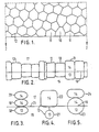
- Figure 1 shows a segment of a blanket of covering members of a preferred embodiment of the invention seen from above.
- Figure 2 is a sectional view of Figure 1 taken through a plane indicated by section line 2-2 in Figure 1 seen from the side.
- Figures 3, 4 and 5 show alternative preferred embodiments of covering members of the invention seen from the side.
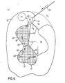
- Figure 6 is a schematic diagram which shows a body of water being heated by the sun utilising covering members and a floating framework of the invention seen from above.
- FIGs 1 and 2 show a segment of a barrier consisting of thousands of covering members 10 and 11 seen in Figure 1 from above and seen in Figure 2 from the side.
- Each covering member is a sealed bag with its wall 12 comprising a thin translucent film of polyethylene plastic which encases a translucent liquid of water 13 and a translucent gas of air 14.
- Each covering member 10 presses against its neighbouring covering members 11 whereby its thin flexible wall 12 conforms to the shape of the contacting part of the neighbouring covering members'thin flexible walls 12.
- Above the blanket of covering members 10 and 11 is air 17.
- the blanket of covering members 10 and 11 floats on a body of water 15.
- the surface of the body of water 15 and the surface 16 of the liquid of water 13 inside the covering members 10 and 11 ar approximately at the same elevation.
- the liquid and the gas inside the covering member may biL separated by a film of plastic at 16 to prevent condensation of liquid on the upper wall of the covering member.
- the radiation from the sun comes from above and passes through the blanket of covering members 10 and 11, since the gas of air 14 and the liquid of water 13 and the polyethylene plastic all are translucent.
- the radiation from the sun continues into the body of water 15 where it is converted into heat. Some of the radiation will strike the bottom of the water, now shown, which has a dark colour and the radiation will here be converted to heat, which will be transferred to the body of water 15 by conduction and convection.
- the blanket of covering members 10 and 11 reduces heat loss from the heated water 17.
- the continuous blanket of covering members reduces heat absorbing evaporation from the body of water 15 to the air 17, and thermally insulates the body of water 15 from the air 17, since the gas of air 14 inside the cover members 10 and 11 is a good heat insulator.
- FIG. 3 shows alternative embodiments of the cover members.
- the cover member shown in Figure 3 consists of three separate compartments.
- the bottom compartment 18 is submerged below the surface of the water 25 and contains a liquid of water 13; the middle compartment 19 and the upper compartment 20 are floating and upheld in the air 17 and mainly above the surface of the water 25, and contain a gas of air' 14.
- This embodiment of a cover member has a particularly high insulating effect since heat in order to escape from the body of water 15 will have to pass through all three compartments 18, 19 and 20.
- the cover member shown in Figure 4 consists of two separate compartments.
- the bottom compartment 21 is submerged below the surface of the water and contains a liquid of water 13.
- the top compartment 22 is mainly in the air 17 floating on the body of water 15 and contains a gas of air 14.
- the bottom compartment 21 is connected to the top compartment 22 and its wall 12 encases the liquid of water 13 and the gas of air 14.
- the cover member shown in Figure 5 consists of two separate compartments.
- the bottom compartment 23 floats in the body of water 15. Some of the compartment 23 is below the surface of the water 15 and some of the compartment 23 is in the air 17 above the surface 25 of the water 15. The surface 25 of the body of water 15 and the surface 16 of the liquid of water 13 inside the compartment 23 are approximately at the same elevation.
- the top compartment 24 is elevated in the air 17 and contains a gas of air 14.
- This embodiment of a cover meter has a very high insulating effect since heat in order to escape from the body of water 15 will have to pass through the liquid of water 13 and the gas of air 14 on the bottom compartment 23, and the gas of air 14 at the top compartment 24.
- Figure 6 illustrates how the solar heating of water utilizing cover members can be used to facilitate most of man's basic needs, such as power, fresh water, irrigation for agriculture, acquaculture, and chemicals such as fuel, fertilizer and purification of minerals.
- FIG. 6 Shown in Figure 6 is a tropical island in the ocean 51.
- a lagoon 52 which is connected to the ocean 51 through the opening 53.
- a coral reef 54 shields the opening 53 of the lagoon 52 from tall waves.
- a number of dykes 55 have been built whereby the body of water in the lagoon has been divided into a number of basins: a basin 56 for aquaculture, a basin 57 for primary heating of water, and a basin 58 for secondary heating of water.
- a floating framework 59 and 66 respectively, which provides separate frames 60 into which blankets of cover members are placed.
- the floating frameworks 59 and 66 are moored at many places to the bottom of the lagoon 52 and to the shoreline 61 of the lagoon 52 and the dykes 55.
- a current state-of-the-art ocean thermal energy conversion system 62 Located near the basin 58 for secondary heating of water is a current state-of-the-art ocean thermal energy conversion system 62 as one of the systems described for example in the Proceedings of the Eighth Ocean Energy Conference held June 7-11, 1981 in Washington, D.C.
- the conversion system 62 is connected by electric cable 63 to chemical plant 64.
- chemical plant 64 Leading from a depth of approximately 1 km on the ocean bottom to the conversion system is a cold water pipe 65.
- This basin is covered with a blanket of cover members the type illustrated in Figure 5, the blanket of cover members is placed in separate frames of a floating framework 59.
- this basin 58 for secondary heating of water its temperature increases from about 40°C to 47°, at which temperature it again enters the conversion system 62. During the conversion process the temperature of the water decreases to about 17°C and is hereafter discarded to the ocean.
- the power is directed to a chemical plant 64 which converts ocean water to fresh water used for irrigation of local agriculture.
- the chemical plant 64 may also purify minerals, produce fertilizer and produce fuel for export purposes.
- An ideally located island which advantageously would be able to utilize the coverites of this invention would be Grand Cayman in the Caribbean.
- the total required length of the cold water pipe would be less than 3 km; a lagoon of about 60 square kilometers is found on the northern part of the island which on the average is only 3 meters deep.
- Many other places in the world have swamps, lakes or lagoons which at present do not contribute to the economy of man, and which would be well suited for projects which would involve the heating of water.
Landscapes
- Engineering & Computer Science (AREA)
- Physics & Mathematics (AREA)
- Life Sciences & Earth Sciences (AREA)
- Sustainable Development (AREA)
- Sustainable Energy (AREA)
- Thermal Sciences (AREA)
- Chemical & Material Sciences (AREA)
- Combustion & Propulsion (AREA)
- Mechanical Engineering (AREA)
- General Engineering & Computer Science (AREA)
- Heat Treatment Of Water, Waste Water Or Sewage (AREA)
Priority Applications (2)
| Application Number | Priority Date | Filing Date | Title |
|---|---|---|---|
| AT83302416T ATE35453T1 (de) | 1983-04-28 | 1983-04-28 | Wassererwaermung durch sonnenenergie unter verwendung von abdeckelementen. |
| DE8383302416T DE3377226D1 (en) | 1983-04-28 | 1983-04-28 | Solar heating of water utilizing covering members |
Applications Claiming Priority (1)
| Application Number | Priority Date | Filing Date | Title |
|---|---|---|---|
| US32048481A | 1981-11-12 | 1981-11-12 |
Publications (2)
| Publication Number | Publication Date |
|---|---|
| EP0123743A1 EP0123743A1 (en) | 1984-11-07 |
| EP0123743B1 true EP0123743B1 (en) | 1988-06-29 |
Family
ID=23246635
Family Applications (1)
| Application Number | Title | Priority Date | Filing Date |
|---|---|---|---|
| EP83302416A Expired EP0123743B1 (en) | 1981-11-12 | 1983-04-28 | Solar heating of water utilizing covering members |
Country Status (5)
| Country | Link |
|---|---|
| EP (1) | EP0123743B1 (esLanguage) |
| AU (1) | AU565462B2 (esLanguage) |
| CA (1) | CA1223163A (esLanguage) |
| GB (1) | GB2109105B (esLanguage) |
| IN (1) | IN159030B (esLanguage) |
Families Citing this family (1)
| Publication number | Priority date | Publication date | Assignee | Title |
|---|---|---|---|---|
| ATE57431T1 (de) * | 1983-10-12 | 1990-10-15 | Shimon Klier | Lichtdurchlaessiger isolationsapparat. |
Family Cites Families (4)
| Publication number | Priority date | Publication date | Assignee | Title |
|---|---|---|---|---|
| DE2139986A1 (de) * | 1971-08-10 | 1973-02-22 | Heinz Friebe | Waermesperre fuer schwimmbecken |
| DE2527414A1 (de) * | 1975-06-20 | 1976-12-30 | Geb Oehrig Edith Boening | Konvexdach als sonnenheizung zur dachung von gebaeuden, haeusern und hohlkoerpern |
| DE2552559A1 (de) * | 1975-11-24 | 1977-06-02 | Heinz Dipl Chem Dr Piffko | Isoliermatte mit solarkollektoreffekt |
| GB1597459A (en) * | 1977-12-14 | 1981-09-09 | Robinson F J L | Apparatus for extracting heat from solar energy |
-
1982
- 1982-06-11 GB GB08216966A patent/GB2109105B/en not_active Expired
-
1983
- 1983-04-20 AU AU13817/83A patent/AU565462B2/en not_active Ceased
- 1983-04-28 EP EP83302416A patent/EP0123743B1/en not_active Expired
- 1983-05-02 IN IN535/CAL/83A patent/IN159030B/en unknown
- 1983-05-09 CA CA000427771A patent/CA1223163A/en not_active Expired
Also Published As
| Publication number | Publication date |
|---|---|
| AU1381783A (en) | 1984-10-25 |
| EP0123743A1 (en) | 1984-11-07 |
| GB2109105A (en) | 1983-05-25 |
| GB2109105B (en) | 1985-06-12 |
| AU565462B2 (en) | 1987-09-17 |
| CA1223163A (en) | 1987-06-23 |
| IN159030B (esLanguage) | 1987-03-14 |
Similar Documents
| Publication | Publication Date | Title |
|---|---|---|
| US4108373A (en) | Method and an installation for the air-conditioning of greenhouses and frames | |
| DE2543687C2 (esLanguage) | ||
| CN102060340B (zh) | 一种自动式太阳能膜蒸馏海水淡化装置 | |
| US4470544A (en) | Method of and means for weather modification | |
| US4959127A (en) | System for desalinization of saltwater | |
| Mowla et al. | Mathematical modelling of solar stills in Iran | |
| US4613409A (en) | High rate solar still and process | |
| US4467786A (en) | Solar heating of water utilizing coverites | |
| US4582048A (en) | Floating blanket barrier utilizing coverites | |
| US4215672A (en) | Method and an installation for the air-conditioning of greenhouses and frames | |
| CN201634461U (zh) | 一种漂浮式海水自动淡化设备 | |
| EP0123743B1 (en) | Solar heating of water utilizing covering members | |
| DE2650482C3 (de) | Vorrichtung zur Entsalzung von Meerwasser durch Destillation mittels Sonnenlicht | |
| Tiwari et al. | Studies on various designs of solar distillation systems | |
| US4470403A (en) | Saltless solar pond | |
| Tabor | Solar ponds | |
| CN2219290Y (zh) | 一种海水淡化装置 | |
| EP0462306A1 (de) | Verfahren und Vorrichtung zur Entmineralisierung von Wasser mit Sonnenenergie in einem kreislaufgeschlossenem Luftsystem | |
| CN107986360A (zh) | 制造蒸馏水的简易结构 | |
| GB1599809A (en) | Water distillation plant | |
| JPS59189252A (ja) | 太陽熱温水製造方法及び太陽熱温水製造装置 | |
| EP0045821A1 (de) | Multifunktionales Rinnendach und Montageverfahren | |
| DE102004028621A1 (de) | Vorrichtung zur Gewinnung von Wasserdampf | |
| JPS5777855A (en) | Solar pond | |
| JPH07290041A (ja) | 蒸留水の製造方法 |
Legal Events
| Date | Code | Title | Description |
|---|---|---|---|
| PUAI | Public reference made under article 153(3) epc to a published international application that has entered the european phase |
Free format text: ORIGINAL CODE: 0009012 |
|
| AK | Designated contracting states |
Designated state(s): AT BE CH DE FR LI NL SE |
|
| 17P | Request for examination filed |
Effective date: 19850404 |
|
| 17Q | First examination report despatched |
Effective date: 19860131 |
|
| R17C | First examination report despatched (corrected) |
Effective date: 19860910 |
|
| GRAA | (expected) grant |
Free format text: ORIGINAL CODE: 0009210 |
|
| AK | Designated contracting states |
Kind code of ref document: B1 Designated state(s): AT BE CH DE FR LI NL SE |
|
| PG25 | Lapsed in a contracting state [announced via postgrant information from national office to epo] |
Ref country code: NL Effective date: 19880629 Ref country code: LI Effective date: 19880629 Ref country code: CH Effective date: 19880629 Ref country code: BE Effective date: 19880629 Ref country code: AT Effective date: 19880629 |
|
| REF | Corresponds to: |
Ref document number: 35453 Country of ref document: AT Date of ref document: 19880715 Kind code of ref document: T |
|
| PG25 | Lapsed in a contracting state [announced via postgrant information from national office to epo] |
Ref country code: SE Effective date: 19880630 |
|
| REF | Corresponds to: |
Ref document number: 3377226 Country of ref document: DE Date of ref document: 19880804 |
|
| ET | Fr: translation filed | ||
| REG | Reference to a national code |
Ref country code: CH Ref legal event code: PL |
|
| NLV1 | Nl: lapsed or annulled due to failure to fulfill the requirements of art. 29p and 29m of the patents act | ||
| PLBE | No opposition filed within time limit |
Free format text: ORIGINAL CODE: 0009261 |
|
| STAA | Information on the status of an ep patent application or granted ep patent |
Free format text: STATUS: NO OPPOSITION FILED WITHIN TIME LIMIT |
|
| 26N | No opposition filed | ||
| PGFP | Annual fee paid to national office [announced via postgrant information from national office to epo] |
Ref country code: FR Payment date: 19970327 Year of fee payment: 15 |
|
| PGFP | Annual fee paid to national office [announced via postgrant information from national office to epo] |
Ref country code: DE Payment date: 19970423 Year of fee payment: 15 |
|
| PG25 | Lapsed in a contracting state [announced via postgrant information from national office to epo] |
Ref country code: FR Free format text: THE PATENT HAS BEEN ANNULLED BY A DECISION OF A NATIONAL AUTHORITY Effective date: 19980430 |
|
| PG25 | Lapsed in a contracting state [announced via postgrant information from national office to epo] |
Ref country code: DE Free format text: LAPSE BECAUSE OF NON-PAYMENT OF DUE FEES Effective date: 19990202 |
|
| REG | Reference to a national code |
Ref country code: FR Ref legal event code: ST |