EP0123608A1 - Vibrant shaft viscosimeter - Google Patents
Vibrant shaft viscosimeter Download PDFInfo
- Publication number
- EP0123608A1 EP0123608A1 EP84400747A EP84400747A EP0123608A1 EP 0123608 A1 EP0123608 A1 EP 0123608A1 EP 84400747 A EP84400747 A EP 84400747A EP 84400747 A EP84400747 A EP 84400747A EP 0123608 A1 EP0123608 A1 EP 0123608A1
- Authority
- EP
- European Patent Office
- Prior art keywords
- sensor
- electromagnet
- rod
- signal
- output signal
- Prior art date
- Legal status (The legal status is an assumption and is not a legal conclusion. Google has not performed a legal analysis and makes no representation as to the accuracy of the status listed.)
- Granted
Links
- 229910052751 metal Inorganic materials 0.000 claims abstract description 5
- 239000002184 metal Substances 0.000 claims abstract description 5
- 238000007598 dipping method Methods 0.000 claims abstract description 3
- 230000005284 excitation Effects 0.000 claims description 15
- 238000005259 measurement Methods 0.000 claims description 14
- 239000000523 sample Substances 0.000 claims description 9
- 230000003321 amplification Effects 0.000 claims description 3
- 230000005294 ferromagnetic effect Effects 0.000 claims description 3
- 238000003199 nucleic acid amplification method Methods 0.000 claims description 3
- 208000019300 CLIPPERS Diseases 0.000 claims 2
- 230000006978 adaptation Effects 0.000 claims 2
- 208000021930 chronic lymphocytic inflammation with pontine perivascular enhancement responsive to steroids Diseases 0.000 claims 2
- 239000003990 capacitor Substances 0.000 description 4
- 230000010355 oscillation Effects 0.000 description 4
- 238000012986 modification Methods 0.000 description 3
- 230000004048 modification Effects 0.000 description 3
- 229910001220 stainless steel Inorganic materials 0.000 description 3
- 239000010935 stainless steel Substances 0.000 description 3
- 239000004020 conductor Substances 0.000 description 2
- 238000010586 diagram Methods 0.000 description 2
- 239000007788 liquid Substances 0.000 description 2
- 235000011837 pasties Nutrition 0.000 description 2
- BASFCYQUMIYNBI-UHFFFAOYSA-N platinum Chemical compound [Pt] BASFCYQUMIYNBI-UHFFFAOYSA-N 0.000 description 2
- 238000003466 welding Methods 0.000 description 2
- 238000004804 winding Methods 0.000 description 2
- BQCADISMDOOEFD-UHFFFAOYSA-N Silver Chemical compound [Ag] BQCADISMDOOEFD-UHFFFAOYSA-N 0.000 description 1
- 229910000831 Steel Inorganic materials 0.000 description 1
- 238000005219 brazing Methods 0.000 description 1
- 238000006073 displacement reaction Methods 0.000 description 1
- 238000010894 electron beam technology Methods 0.000 description 1
- 238000001914 filtration Methods 0.000 description 1
- 238000007654 immersion Methods 0.000 description 1
- 238000009434 installation Methods 0.000 description 1
- 238000000034 method Methods 0.000 description 1
- 210000000056 organ Anatomy 0.000 description 1
- 229910052697 platinum Inorganic materials 0.000 description 1
- 230000001681 protective effect Effects 0.000 description 1
- 238000007789 sealing Methods 0.000 description 1
- 229910052709 silver Inorganic materials 0.000 description 1
- 239000004332 silver Substances 0.000 description 1
- 239000010959 steel Substances 0.000 description 1
- 238000003860 storage Methods 0.000 description 1
Images

Classifications
-
- G—PHYSICS
- G01—MEASURING; TESTING
- G01N—INVESTIGATING OR ANALYSING MATERIALS BY DETERMINING THEIR CHEMICAL OR PHYSICAL PROPERTIES
- G01N11/00—Investigating flow properties of materials, e.g. viscosity, plasticity; Analysing materials by determining flow properties
- G01N11/10—Investigating flow properties of materials, e.g. viscosity, plasticity; Analysing materials by determining flow properties by moving a body within the material
- G01N11/16—Investigating flow properties of materials, e.g. viscosity, plasticity; Analysing materials by determining flow properties by moving a body within the material by measuring damping effect upon oscillatory body
Definitions
- the invention relates to vibrating rod viscometers of the type comprising a base connected to a region of a straight metal rod, situated between the ends of the rod, one of which, opposite to that intended for dipping in the product whose viscosity is to be measured, is provided with means for transversely vibrating the rod and with a motion sensor. It finds an application in all fields where it is necessary to measure in real time the viscosity of a liquid or pasty product, in circulation or immobile, at a pressure and / or at a temperature which can vary within wide limits.
- Viscosimeters of this type are known (FR-A-899 057).
- the means for transversely vibrating the rod are supplied by a constant frequency generator.
- the immersion depth must be varied, which is unacceptable in an industrial installation. Consequently, these viscometers have insufficient accuracy for most needs and, moreover, they allow measurements only in a low viscosity range. For this reason, they were abandoned in favor of viscometers whose vibrating organ is in the form of a hairpin (FR-A-2 353 847).
- the invention aims to provide a viscometer of the type defined above which better meets those previously known to the requirements of practice, in particular in that it has increased precision and a greater operating range and in that it is capable of '' be equipped with means making the measurement practically independent of the temperature in a wide range of values.
- the invention provides in particular a viscometer in which said means comprise a ferromagnetic element, generally a permanent magnet, fixed to the rod and placed in the air gap of an electromagnet, and a winding supply circuit of the electromagnet which receives the output signal from the sensor and slaves the supply frequency of the winding to the natural frequency of the rod.
- said means comprise a ferromagnetic element, generally a permanent magnet, fixed to the rod and placed in the air gap of an electromagnet, and a winding supply circuit of the electromagnet which receives the output signal from the sensor and slaves the supply frequency of the winding to the natural frequency of the rod.
- Such a viscometer allows measurements to be made over a very wide range of values, typically from 1 to 1,000,000 cpo.
- the lifespan of the excitation device is much longer than that of a conventional rotating cam system, presenting rapid wear of the bearings, axes and springs in continuous operation.
- the rod will generally be made up by a straight metal needle of small diameter mounted coaxially in a section of tube, one end of which is fixed to the base and the other end of which is fixed to the needle, the transverse vibration node being placed between the ends of the tube.
- the measurement can be carried out by several different processes.
- the circuit is controlled so as to maintain constant the amplitude of the output signal from the sensor and the measurement signal representative of the viscosity is the power supplied to the electromagnet.
- the circuit supplies the electromagnet with constant power and the sensor output signal constitutes the measurement signal.
- sensors can be used, in particular electromagnetic sensors.
- a Hall probe which has good linearity and which is commercially available in the form of a complete temperature compensated circuit.
- the output signal of the probe like the vibration of the rod, is very substantially sinusofdal; but it is advantageous to excite the coil in square signals, obtained by strong amplification and clipping of the circuit supplied by the probe. This solution allows an extremely safe starting of the system, without external excitation, the slightest vibration, always present in reality, sufficient to trigger the operation.
- the electromechanical part of the viscometer shown in Figure 1, comprises a base 10, intended to be fixed on the container or the pipe in which the liquid or pasty product whose viscosity is to be measured.
- a base 10 intended to be fixed on the container or the pipe in which the liquid or pasty product whose viscosity is to be measured.
- an elastic tube 12 made of metal (stainless steel in general).
- a cylindrical needle 14 disposed coaxially with the tube 12 protrudes on both sides of the latter and it is fixed to it in an intermediate zone, for example by silver brazing or welding by electron beam.
- Means for making the rod 16 constituted by the assembly of the needle 14 (generally made of hard steel or stainless steel) and the tube 12 oscillate transversely in flexion, comprise a permanent magnet 18 with a strong coercive field fixed at the end from the needle which is far from that which plunges into the product.
- the magnet 18 is placed in the air gap of an electromagnet 20 provided with an excitation coil 22 and carried by a bracket 24 secured to the base 10.
- the bracket 24 also carries a displacement sensor 26, which will subsequently be assumed to be a Hall probe, cooperating with a magnet 28 carried by the needle 14.
- the assembly thus formed is placed in a protective hood 30 fixed to the base 10 and pierced with a hole 32 for the outlet of the electrical conductors connecting the sensor 26 and the coil 22 with the external circuits.
- a finned sleeve 34 can be provided around the bell 30 to dissipate the heat.
- This arrangement allows the rod 16 to be produced using a simple mechanical assembly. As an example, it can be indicated that satisfactory results are obtained with a stainless steel tube 12 50 mm long, 4 mm in internal diameter and 0.25 mm thick, and a needle of 150 mm long and 3 mm in diameter. A higher needle length or diameter will be chosen when the viscosity to be measured is lower.
- the circuits associated with the electro-mechanical part can have the constitution shown in FIG. 2, provided for measuring the braking of the oscillation, therefore the viscosity, by determining the amplitude of the oscillation at constant excitation power.
- This circuit supplies the excitation signals in the form of square signals of constant voltage, at least at constant temperature. Whenever the operating temperature range is large, this circuit is completed by means of compensating for the variation in resistance of the coil 22 as a function of the temperature.
- the sensor 26 constituted by a Hall probe commercially available in the form of a wafer provided with its own temperature compensation circuit (92 SS12-2 probe from HONEYWELL for example) provides a sinusoidal output signal of proportional amplitude. to that of oscillation in a large area.
- the output of this sensor drives a measurement branch and an excitation branch of the electromagnet 22.
- the excitation branch of the electromagnet comprises an operational amplifier 36 mounted in open loop so as to have a very high gain.
- Two Zener diodes 38 mounted head to tail between the output of amplifier 36 and ground clip the signal and transform it into square slots.
- Zener diodes having a starting voltage of 5.1 V type BZX 46C whose characteristics vary little with the temperature.
- the square signal thus obtained is applied to a second operational amplifier 40 mounted as a follower which, in the illustrated embodiment, drives an amplifier 42 mounted as a summator and whose role will appear below.
- the output signal of the latter is applied to the coil 22 via an operational amplifier 44 for gain adjustment.
- the circuit shown in Figure 2 includes temperature compensation means for supplying square signals, at the output frequency of the sensor 26, of amplitude determined according to the temperature variations of the coil.
- This compensation circuit will not be described in detail, its general constitution possibly being conventional and based on operational amplifiers.
- This 4-5 Counterclaims preiavé circuit receives a signal at the output of the amolificateur 40 and a signal provided by a temperature probe 48 placed close to the coil 22.
- the temperature sensor 48 can in particular be constituted by a resistance thermometer platinum 100n at 0 ° C type K 201 S (THERMO-EST).
- the summation of the output signal from the amplifier 40 and the temperature compensation signal is effected by a network of resistors 50, 52 connected to the inverting input of the operational amplifier 42 so that the latter performs a summons.
- the measurement branch of the circuit of FIG. 2 comprises an operational amplifier 54 followed by a rectifying diode 56 and a storage capacitor 58 so as to operate as a rectifier-integrator.
- the continuous signal across the capacitor 58 drives an amplifier 60 mounted as an impedance matching follower and is supplied to a recorder 62 which can be of any suitable type.
- the viscometer which has just been described guarantees the excitation of the rod at its natural frequency of resonance, whatever the product to be measured; measures the amplitude of oscillation without mechanical contact; prevents any wear of the excitation mechanism; and, finally, by its very design, is insensitive to disturbances of the electrical network in voltage and frequency, being supplied with direct current. In addition, it is capable of operating in any orientation and has a small footprint.
- the operation of the viscometer resulting from the foregoing description and its constitution, it will suffice here to consider it briefly.
- the viscometer is mounted so that the entire length of tube 12 and the portion of rod 14 which projects beyond it is immersed in the product.
- the measurement and excitation circuit is energized and operation takes place immediately, without any external excitation.
- the electronics can be placed at a great distance from the electro-mechanical part without disadvantage.
- a grommet can be mounted on the bell 30 to allow passage to the various conductors required, usually two for the coil 22, three for the Hall sensor 26 and three for the compensation temperature sensor.
- sensors other than a Hall probe can be used.
- Each particular type of sensor will generally require its own temperature compensation circuit.
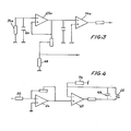
- FIG. 3 shows the head part of a measurement circuit which uses an electromagnetic sensor 26a, provided with a filtering capacitor 64.
- the signal supplied is applied to a looped operational amplifier 40a which drives an open loop amplifier 36a.
- a coil 66 brought to the same temperature as the sensor provides compensation. It links a connection to the measurement loop to ground.
- the temperature compensation circuit of the coil 22 can be eliminated by operating it at constant current. In FIG. 4, this result is achieved by a modification of the excitation branch of FIG. 2.
- the coil 22 is inserted in the feedback loop of the operational amplifier 42 which thus automatically takes into account the variations d coil impedance.
- the circuit is completed by a capacitor 68 for adjusting to the average resonant frequency and by a current limiting resistor 70 ensuring safety.
Landscapes
- Physics & Mathematics (AREA)
- Health & Medical Sciences (AREA)
- Life Sciences & Earth Sciences (AREA)
- Chemical & Material Sciences (AREA)
- Analytical Chemistry (AREA)
- Biochemistry (AREA)
- General Health & Medical Sciences (AREA)
- General Physics & Mathematics (AREA)
- Immunology (AREA)
- Pathology (AREA)
- Investigating Or Analyzing Materials By The Use Of Magnetic Means (AREA)
Abstract
Le viscosimètre comporte une embase (10) reliée à une région d'une aiguille métallique droite (14) située entre les extrémités de l'aiguille par un tronçon de tube élastique (12) coaxial à l'aiguille. L'extrémité de l'aiguille opposée à celle destinée à tremper dans le produit dont la viscosité est à mesurer est munie d'un aimant (18) placé dans l'entrefer d'un électro-aimant (20) de mise en vibration transversale. La bobine (22) de cet électro-aimant est alimentée par un circuit à la fréquence propre de l'aiguille, détectée par un capteur (26) coopérant avec le même extrémité de l'aiguille.The viscometer has a base (10) connected to a region of a straight metal needle (14) located between the ends of the needle by a section of elastic tube (12) coaxial with the needle. The end of the needle opposite to that intended for dipping in the product whose viscosity is to be measured is provided with a magnet (18) placed in the air gap of an electromagnet (20) for transverse vibration . The coil (22) of this electromagnet is supplied by a circuit at the natural frequency of the needle, detected by a sensor (26) cooperating with the same end of the needle.
Description
L'invention concerne les viscosimètres à tige vibrante du type comportant une embase reliée à une région d'une tige métallique droite, située entre les extrémités de la tige dont l'une, opposée à celle destinée à tremper dans le produit dont la viscosité est à mesurer, est munie de moyens de mise en vibration transversale de la tige et d'un capteur de mouvement. Elle trouve une application dans tous les domaines où il est nécessaire de mesurer en temps réel la viscosité d'un produit liquide ou pâteux, en circulation ou immobile, à une pression et/ou à une température pouvant varier dans de larges limites.The invention relates to vibrating rod viscometers of the type comprising a base connected to a region of a straight metal rod, situated between the ends of the rod, one of which, opposite to that intended for dipping in the product whose viscosity is to be measured, is provided with means for transversely vibrating the rod and with a motion sensor. It finds an application in all fields where it is necessary to measure in real time the viscosity of a liquid or pasty product, in circulation or immobile, at a pressure and / or at a temperature which can vary within wide limits.
On connaît des viscosimètres de ce type (FR-A-899 057). Les moyens de mise en vibration transversale de la tige sont alimentés par un générateur à fréquence constante. Pour la rendre à peu près égale à la fréquence propre de la tige, on doit faire varier la profondeur d'immersion, ce qui est inacceptable dans une installation industrielle. En conséquence, ces viscosimètres ont une précision insuffisante pour la plupart des besoins et, de plus, ils ne permettent des mesures que dans une plage de viscosité faible. Pour cette raison, ils ont été abandonnés au profit de viscosimètres dont l'organe vibrant est en forme d'épingle à cheveux (FR-A-2 353 847).Viscosimeters of this type are known (FR-A-899 057). The means for transversely vibrating the rod are supplied by a constant frequency generator. To make it roughly equal to the natural frequency of the rod, the immersion depth must be varied, which is unacceptable in an industrial installation. Consequently, these viscometers have insufficient accuracy for most needs and, moreover, they allow measurements only in a low viscosity range. For this reason, they were abandoned in favor of viscometers whose vibrating organ is in the form of a hairpin (FR-A-2 353 847).
L'invention vise à fournir un viscosimètre du type ci-dessus défini répondant mieux que ceux antérieurement connus aux exigences de la pratique, notamment en ce qu'il présente une précision et un domaine de fonctionnement accrus et en ce qu'il est susceptible d'être équipé de moyens rendant la mesure pratiquement indépendante de la température dans une gamme de valeurs importante.The invention aims to provide a viscometer of the type defined above which better meets those previously known to the requirements of practice, in particular in that it has increased precision and a greater operating range and in that it is capable of '' be equipped with means making the measurement practically independent of the temperature in a wide range of values.
Dans ce but, l'invention propose notamment un viscosimètre dans lequel lesdits moyens comportent un élément ferromagnétique, généralement un aimant permanent, fixé à la tige et placé dans l'entrefer d'un électro-aimant, et un circuit d'alimentation du bobinage de l'électro-aimant qui reçoit le signal de sortie du capteur et asservit la fréquence d'alimentation du bobinage à la fréquence propre de la tige.To this end, the invention provides in particular a viscometer in which said means comprise a ferromagnetic element, generally a permanent magnet, fixed to the rod and placed in the air gap of an electromagnet, and a winding supply circuit of the electromagnet which receives the output signal from the sensor and slaves the supply frequency of the winding to the natural frequency of the rod.
Un tel viscosimètre permet d'effectuer des mesures dans un domaine très large de valeurs, typiquement de 1 à 1 000 000 cpo. La durée de vie du dispositif d'excitation est beaucoup plus longue que celle d'un système classique à came tournante, présentant une usure rapide des paliers, axes et ressorts en fonctionnement continu. La tige sera généralement constituée par une aiguille métallique droite de faible diamètre montée coaxialement dans un tronçon de tube dont une extrémité est fixée à l'embase et dont l'autre extrémité est fixée à l'aiguille, le noeud de vibration transversale se plaçant entre les extrémités du tube. La mesure peut être effectuée par plusieurs processus différents. Dans une première variante, le circuit est asservi de façon à maintenir constante l'amplitude du signal de sortie du capteur et le signal de mesure représentatif de la viscos ité est la puissance fournie à l'électro-aimant. Dans une autre variante, le circuit fournit à l'électro-aimant une puissance constante et le - signal de sortie du capteur constitue le signal de mesure.Such a viscometer allows measurements to be made over a very wide range of values, typically from 1 to 1,000,000 cpo. The lifespan of the excitation device is much longer than that of a conventional rotating cam system, presenting rapid wear of the bearings, axes and springs in continuous operation. The rod will generally be made up by a straight metal needle of small diameter mounted coaxially in a section of tube, one end of which is fixed to the base and the other end of which is fixed to the needle, the transverse vibration node being placed between the ends of the tube. The measurement can be carried out by several different processes. In a first variant, the circuit is controlled so as to maintain constant the amplitude of the output signal from the sensor and the measurement signal representative of the viscosity is the power supplied to the electromagnet. In another variant, the circuit supplies the electromagnet with constant power and the sensor output signal constitutes the measurement signal.
On peut utiliser différents types de capteurs, notamment des capteurs électro-magnétiques. Toutefois, il sera en général avantageux d'utiliser une sonde de Hall, qui présente une bonne linéarité et qui est disponible dans le commerce sous forme d'un circuit complet compensé en température.Different types of sensors can be used, in particular electromagnetic sensors. However, it will generally be advantageous to use a Hall probe, which has good linearity and which is commercially available in the form of a complete temperature compensated circuit.
Le signal de sortie de la sonde, comme la vibration de la tige, est très sensiblement sinusofdal; mais il est avantageux d'exciter la bobine en signaux carrés, obtenus par forte amplification et écrêtage du circuit fourni par la sonde. Cette solution permet un démarrage extrêmement sûr du système, sans excitation extérieure, la moindre vibration, toujours présente dans la réalité, suffisant à déclencher le fonctionnement.The output signal of the probe, like the vibration of the rod, is very substantially sinusofdal; but it is advantageous to excite the coil in square signals, obtained by strong amplification and clipping of the circuit supplied by the probe. This solution allows an extremely safe starting of the system, without external excitation, the slightest vibration, always present in reality, sufficient to trigger the operation.
L'invention sera mieux comprise à la lecture de la description qui suit d'un viscosimètre qui en constitue un mode particulier de réalisation, donné à titre d'exemple non limitatif.The invention will be better understood on reading the following description of a viscometer which constitutes a particular embodiment thereof, given by way of nonlimiting example.
La description se réfère au dessin qui l'accompagne, dans lequel :
- - la Figure 1 est un schéma de la partie mécanique du viscosimètre, représentée en coupe suivant un plan passant par son axe ;
- - la Figure 2 est un synoptique du circuit de mesure et d'excitation du viscosimètre,
- - les Figures 3 et 4 montrent dès modifications possibles de la Figure 2.
- - Figure 1 is a diagram of the mechanical part of the viscometer, shown in section along a plane passing through its axis;
- - Figure 2 is a block diagram of the measurement and excitation circuit of the viscometer,
- - Figures 3 and 4 show possible modifications to Figure 2.
La partie électromécanique du viscosimètre, montrée en Figure 1, comprend une embase 10, prévue pour être fixée sur le récipient ou la conduite dans lequel se trouve le produit liquide ou pâteux dont la viscosité est à mesurer. A l'embase 10 est fixé, généralement par emmanchement et soudage, un tube élastique 12 en métal (acier inoxydable en général). Une aiguille cylindrique 14 disposée coaxialement au tube 12 fait saillie des deux côtés de ce dernier et elle lui est fixée en une zone intermédiaire, par exemple par brasage à l'argent ou soudage par faisceau d'électrons. Des moyens pour faire osciller transversalement en flexion la tige 16 constituée par l'assemblage de l'aiguille 14 (généralement en acier dur ou en acier inoxydable) et du tube 12, comprennent un aimant permanent 18 à fort champ coercitif fixé à l'extrémité de l'aiguille qui est éloignée de celle qui plonge dans le produit. L'aimant 18 est placé dans l'entrefer d'un électro-aimant 20 muni d'une bobine d'excitation 22 et porté par une potence 24 solidaire de l'embase 10. La potence 24 porte également un capteur de déplacement 26, qu'on supposera par la suite être une sonde de Hall, coopérant avec un aimant 28 porté par l'aiguille 14.The electromechanical part of the viscometer, shown in Figure 1, comprises a
L'ensemble ainsi constitué est placé dans une cloche de protection 30 fixée à l'embase 10 et percée d'un trou 32 de sortie des conducteurs électriques de jonction du capteur 26 et de la bobine 22 avec les circuits extérieurs. Un manchon à ailettes 34 peut être prévu autour de la cloche 30 pour évacuer la chaleur.The assembly thus formed is placed in a
Cette disposition permet de réaliser la tige 16 à l'aide d'un montage mécanique simple. A titre d'exemple, on peut indiquer qu'on obtient des résultats satisfaisants avec un tube 12 en acier inoxydable de 50 mm de long, de 4 mm de diamètre interne et de 0,25 mm d'épaisseur, et une aiguille de 150 mm de long et de 3 mm de diamètre. On choisira une longueur ou un diamètre d'aiguille plus élevé lorsque la viscosité à mesurer est plus faible.This arrangement allows the
Les circuits associés-à la partie électro-mécanique peuvent avoir la constitution montrée en Figure 2, prévue pour mesurer le freinage de l'oscillation, donc la viscosité, par détermination de l'amplitude de l'oscillation à puissance d'excitation constante. Ce circuit fournit les signaux d'excitation sous forme de signaux carrés de tension constante, du moins à température constante. Chaque fois que la plage de température de fonctionnement est importante, ce circuit est complété par des moyens de compensation de la variation de résistance de la bobine 22 en fonction de la température.The circuits associated with the electro-mechanical part can have the constitution shown in FIG. 2, provided for measuring the braking of the oscillation, therefore the viscosity, by determining the amplitude of the oscillation at constant excitation power. This circuit supplies the excitation signals in the form of square signals of constant voltage, at least at constant temperature. Whenever the operating temperature range is large, this circuit is completed by means of compensating for the variation in resistance of the
Le capteur 26, constitué par une sonde de Hall disponible dans le commerce sous forme de plaquette munie d'un circuit de compensation propre en température (sonde 92 SS12-2 de HONEYWELL par exemple) fournit un signal sinusoïdal de sortie.d'amplitude proportionnelle à celle de l'oscillation dans un large domaine. La sortie de ce capteur attaque une branche de mesure et une branche d'excitation de l'électro-aimant 22.The
La branche d'excitation de l'électro-aimant comporte un amplificateur opérationnel 36 monté en boucle ouverte de façon à avoir un gain très élevé. Deux diodes Zener 38 montées tête-bêche entre la sortie de l'amplificateur 36 et la masse écrêtent le signal et le transforment en créneaux carrés. On peut notamment utiliser des diodes Zener ayant une tension d'amorçage de 5,1 V type BZX 46C dont les caractéristiques varient peu avec la température.The excitation branch of the electromagnet comprises an
Le signal carré ainsi obtenu est appliqué à un second amplificateur opérationnel 40 monté en suiveur qui, dans le mode de réalisation illustré, attaque un amplificateur 42 monté en sommateur et dont le rôle apparaîtra plus loin. Le signal de sortie de ce dernier est appliqué à la bobine 22 par l'intermédiaire d'un amplificateur opérationnel 44 de réglage de gain.The square signal thus obtained is applied to a second
Le circuit représenté en Figure 2 comporte des moyens de compensation de température destinés à fournir des signaux carrés, à la fréquence de sortie du capteur 26, d'amplitude déterminée en fonction des variations de température de la bobine. Ce circuit de compensation ne sera pas décrit en détail, sa constitution générale pouvant être classique et à base d'amplificateurs opérationnels. Ce circuit de compensation 45 reçoit un signal preiavé à la sortie de l'amolificateur 40 et un signal de température fourni par une sonde 48 placée à proximité de la bobine 22. La sonde de température 48 peut notamment être constituée par une sonde à résistance de platine de 100n à 0°C du type K 201 S (THERMO-EST).The circuit shown in Figure 2 includes temperature compensation means for supplying square signals, at the output frequency of the
La sommation du signal de sortie provenant de l'amplificateur 40 et du signal de compensation de température s'effectue par un réseau de résistances 50, 52 reliées à l'entrée inverseuse de l'amplificateur opérationnel 42 de façon que celui-ci effectue une sommation.The summation of the output signal from the
La branche de mesure du circuit de la Figure 2 comporte un amplificateur opérationnel 54 suivi d'une diode de redressement 56 et d'un condensateur de stockage 58 de façon à fonctionner en redresseur-intégrateur. Le signal continu aux bornes du condensateur 58 attaque un amplificateur 60 monté en suiveur d'adaptation d'impédance et il est fourni à un enregistreur 62 qui peut être de n'importe quel type approprié.The measurement branch of the circuit of FIG. 2 comprises an
On voit que le viscosimètre qui vient d'être décrit garantit l'excitation de la tige à sa fréquence propre de résonance, quel que soit le produit à mesurer ; permet de mesurer l'amplitude d'oscillation sans contact mécanique ; évite toute usure du mécanisme d'excitation ; et, enfin, de par sa conception même, est insensible aux perturbations du réseau électrique en tension et en fréquence, étant alimenté en courant continu. Au surplus, il est capable de fonctionner dans n'importe quelle orientation et présente un encombrement réduit.We see that the viscometer which has just been described guarantees the excitation of the rod at its natural frequency of resonance, whatever the product to be measured; measures the amplitude of oscillation without mechanical contact; prevents any wear of the excitation mechanism; and, finally, by its very design, is insensitive to disturbances of the electrical network in voltage and frequency, being supplied with direct current. In addition, it is capable of operating in any orientation and has a small footprint.
Le fonctionnement du viscosimètre résultant de la description qui précède et de sa constitution, il suffira ici de l'envisager sommairement. Le viscosimètre est monté de façon que l'ensemble du tronçon de tube 12 et de la portion de tige 14 qui en déborde baigne dans le produit. Le circuit de mesure et d'excitation est mis en tension et le fonctionnement intervient immédiatement, sans aucune excitation extérieure. L'électronique peut être placée à distance importante de la partie électro-mécanique sans inconvénient. Lorsque l'étanchéité est requise, un passe-fil peut être monté sur la cloche 30 pour livrer passage aux différents conducteurs nécessaires, habituellement deux pour la bobine 22, trois pour la sonde de Hall 26 et trois pour le capteur de température de compensation.The operation of the viscometer resulting from the foregoing description and its constitution, it will suffice here to consider it briefly. The viscometer is mounted so that the entire length of
De nombreuses variantes de réalisation sont possibles. En particulier, des capteurs autres qu'une sonde de Hall sont utilisables. Chaque type particulier de capteur exigera généralement un circuit de compensation de température propre.Many variant embodiments are possible. In particular, sensors other than a Hall probe can be used. Each particular type of sensor will generally require its own temperature compensation circuit.
La figure 3 montre la partie de tête d'un circuit de mesure qui utilise un capteur électromagnétique 26a, muni d'un condensateur de filtrage 64. Le signal fourni est appliqué à un amplificateur opérationnel bouclé 40a qui attaque un amplificateur en boucle ouverte 36a. Une bobine 66 portée à la même température que le capteur assure la compensation. Elle relie une liaison vers la boucle de mesure à la masse.FIG. 3 shows the head part of a measurement circuit which uses an
On peut supprimer le circuit de compensation de température de la bobine 22 en le faisant fonctionner à courant constant. Sur la figure 4, ce résultat est atteint par une modification de la branche d'excitation de la figure 2. La bobine 22 est insérée dans la boucle de contre- réaction de l'amplificateur opérationnel 42 qui prend ainsi automatiquement en compte les variations d'impédance de la bobine. Le circuit est complété par un condensateur 68 d'ajustement à la fréquence de résonance moyenne et par une résistance de limitation de courant 70 assurant la sécurité.The temperature compensation circuit of the
Claims (8)
Applications Claiming Priority (2)
| Application Number | Priority Date | Filing Date | Title |
|---|---|---|---|
| FR8306238A FR2544496B1 (en) | 1983-04-15 | 1983-04-15 | VIBRATING ROD VISCOSIMETER |
| FR8306238 | 1983-04-15 |
Publications (2)
| Publication Number | Publication Date |
|---|---|
| EP0123608A1 true EP0123608A1 (en) | 1984-10-31 |
| EP0123608B1 EP0123608B1 (en) | 1987-09-16 |
Family
ID=9287922
Family Applications (1)
| Application Number | Title | Priority Date | Filing Date |
|---|---|---|---|
| EP84400747A Expired EP0123608B1 (en) | 1983-04-15 | 1984-04-13 | Vibrant shaft viscosimeter |
Country Status (4)
| Country | Link |
|---|---|
| US (1) | US4558588A (en) |
| EP (1) | EP0123608B1 (en) |
| DE (1) | DE3466289D1 (en) |
| FR (1) | FR2544496B1 (en) |
Cited By (2)
| Publication number | Priority date | Publication date | Assignee | Title |
|---|---|---|---|---|
| EP0949489A1 (en) * | 1998-04-06 | 1999-10-13 | Nohken Inc. | Vibration type level detector |
| US9568408B2 (en) | 2014-12-19 | 2017-02-14 | Halliburton Energy Services, Inc. | Methods for determining rheological quantities of a drilling fluid using apparent viscosity |
Families Citing this family (17)
| Publication number | Priority date | Publication date | Assignee | Title |
|---|---|---|---|---|
| DE3306406A1 (en) * | 1983-02-24 | 1984-08-30 | Ernst 2000 Hamburg Thöne | METHOD AND DEVICE FOR MEASURING THE VISCOSITY OF A LIQUID |
| US4799378A (en) * | 1985-10-21 | 1989-01-24 | Alcor, Inc. | Piezoelectric viscometer |
| GB8705757D0 (en) * | 1987-03-11 | 1987-04-15 | Schlumberger Electronics Uk | Fluid transducer |
| US4754640A (en) * | 1987-03-17 | 1988-07-05 | National Metal And Refining Company, Ltd. | Apparatus and method for determining the viscoelasticity of liquids |
| US4862384A (en) * | 1987-08-03 | 1989-08-29 | Rockwell International Corporation | Method of measuring the dynamic viscosity of a viscous fluid utilizing acoustic transducer |
| DE3738901A1 (en) * | 1987-11-17 | 1989-05-24 | Amelung Gmbh Heinrich | Device for recording the change in state of a liquid |
| US5157962A (en) * | 1989-05-08 | 1992-10-27 | National Metal And Refining Company, Inc. | Vibratory viscometer transducer with isolation support for inline viscosity sensor |
| US5067344A (en) * | 1989-05-08 | 1991-11-26 | Natonal Metal And Refining Company, Inc. | Vibratory viscometer transducer with isolation support for inline viscosity sensor |
| JP2709282B2 (en) * | 1995-03-13 | 1998-02-04 | 山一電機株式会社 | Vibration type test equipment |
| JP2002228668A (en) * | 2001-01-31 | 2002-08-14 | Shimadzu Corp | Automatic sampler |
| US6668621B1 (en) | 2002-06-13 | 2003-12-30 | Hubert Arthur Wright | Viscosity measurement by means of damped resonant vibration normal to an approximate rigid plate |
| WO2004055869A2 (en) * | 2002-12-13 | 2004-07-01 | Texas Instruments Incorporated | Current driver for an analog micromirror device |
| US20040114206A1 (en) * | 2002-12-13 | 2004-06-17 | Pillai Narayana Sateesh | Current driver for an analog micromirror device |
| US6907025B2 (en) * | 2003-06-06 | 2005-06-14 | Interdigital Technology Corporation | Adjusting the amplitude and phase characteristics of transmitter generated wireless communication signals in response to base station transmit power control signals and known transmitter amplifier characteristics |
| US8023439B2 (en) * | 2006-11-20 | 2011-09-20 | Airvana Network Solutions, Inc. | Multicast flow distribution |
| FR2911188B1 (en) * | 2007-01-10 | 2010-03-12 | Fr De Services Soc | METHOD AND SYSTEM USING OSCILLATING ELEMENT FOR DETERMINING PHYSICAL CHARACTERISTICS OF A PRODUCT |
| DE102007034585A1 (en) * | 2007-07-25 | 2009-01-29 | Continental Automotive Gmbh | Arrangement for determining a characteristic of a fluid, sensor device and use in a motor vehicle |
Citations (6)
| Publication number | Priority date | Publication date | Assignee | Title |
|---|---|---|---|---|
| FR899057A (en) * | 1942-10-22 | 1945-05-18 | Ig Farbenindustrie Ag | Viscometer for carrying out measurements and adjustments |
| US2550052A (en) * | 1949-02-21 | 1951-04-24 | Shell Dev | Viscosity meter |
| US3270274A (en) * | 1965-02-15 | 1966-08-30 | Automation Prod | Temperature compensating circuit |
| FR2151336A5 (en) * | 1971-08-20 | 1973-04-13 | Medcraft Inc | |
| FR2353847A1 (en) * | 1976-05-31 | 1977-12-30 | Commissariat Energie Atomique | Vibration viscometer for measurement of liq. under pressure - uses vibrating transmission pin with established node point |
| US4148216A (en) * | 1978-01-18 | 1979-04-10 | Do Mau T | Apparatus for determining the viscous behavior of a liquid during coagulation thereof |
Family Cites Families (5)
| Publication number | Priority date | Publication date | Assignee | Title |
|---|---|---|---|---|
| GB851621A (en) * | 1957-04-29 | 1960-10-19 | Bayer Ag | Viscometer |
| US3585457A (en) * | 1969-05-01 | 1971-06-15 | Fuller Co | Material level sensing device and indicating system |
| US3710614A (en) * | 1971-09-09 | 1973-01-16 | Nat Metal & Refining Co | High precision wide dynamic range viscous loss measuring apparatus |
| US3903732A (en) * | 1974-06-17 | 1975-09-09 | Honeywell Inc | Viscosimeter and densitometer apparatus |
| US4166381A (en) * | 1978-02-24 | 1979-09-04 | E. I. Du Pont De Nemours And Company | Apparatus for determining the viscosity of fluids |
-
1983
- 1983-04-15 FR FR8306238A patent/FR2544496B1/en not_active Expired
-
1984
- 1984-04-09 US US06/598,001 patent/US4558588A/en not_active Expired - Lifetime
- 1984-04-13 DE DE8484400747T patent/DE3466289D1/en not_active Expired
- 1984-04-13 EP EP84400747A patent/EP0123608B1/en not_active Expired
Patent Citations (6)
| Publication number | Priority date | Publication date | Assignee | Title |
|---|---|---|---|---|
| FR899057A (en) * | 1942-10-22 | 1945-05-18 | Ig Farbenindustrie Ag | Viscometer for carrying out measurements and adjustments |
| US2550052A (en) * | 1949-02-21 | 1951-04-24 | Shell Dev | Viscosity meter |
| US3270274A (en) * | 1965-02-15 | 1966-08-30 | Automation Prod | Temperature compensating circuit |
| FR2151336A5 (en) * | 1971-08-20 | 1973-04-13 | Medcraft Inc | |
| FR2353847A1 (en) * | 1976-05-31 | 1977-12-30 | Commissariat Energie Atomique | Vibration viscometer for measurement of liq. under pressure - uses vibrating transmission pin with established node point |
| US4148216A (en) * | 1978-01-18 | 1979-04-10 | Do Mau T | Apparatus for determining the viscous behavior of a liquid during coagulation thereof |
Cited By (3)
| Publication number | Priority date | Publication date | Assignee | Title |
|---|---|---|---|---|
| EP0949489A1 (en) * | 1998-04-06 | 1999-10-13 | Nohken Inc. | Vibration type level detector |
| US6105425A (en) * | 1998-04-06 | 2000-08-22 | Nohken Inc. | Vibration type level detector |
| US9568408B2 (en) | 2014-12-19 | 2017-02-14 | Halliburton Energy Services, Inc. | Methods for determining rheological quantities of a drilling fluid using apparent viscosity |
Also Published As
| Publication number | Publication date |
|---|---|
| FR2544496B1 (en) | 1985-10-11 |
| EP0123608B1 (en) | 1987-09-16 |
| FR2544496A1 (en) | 1984-10-19 |
| US4558588A (en) | 1985-12-17 |
| DE3466289D1 (en) | 1987-10-22 |
Similar Documents
| Publication | Publication Date | Title |
|---|---|---|
| EP0123608B1 (en) | Vibrant shaft viscosimeter | |
| EP0172117A2 (en) | Peristaltic pump provided with pressure measuring means | |
| EP0360673A1 (en) | Process and device for indicating the rate of flow of a compressible fluid circulating through a pressure reducer, and vibration sensor for the same | |
| FR2807162A1 (en) | SURFACE ANALYSIS PROBE FOR AN ATOMIC FORCE MICROSCOPE AND ATOMIC FORCE MICROSCOPE CONTAINING IT | |
| EP0401136B1 (en) | Detection circuit and method for temperature-compensating of the oscillation of a resonating circuit | |
| CA1097765A (en) | No translation available | |
| FR2475229A1 (en) | APPARATUS FOR DETECTING MOTION SPEED AND IN PARTICULAR DEBITMETER | |
| EP0187562A1 (en) | Flow meter with a thermally resistant element | |
| FR2548329A1 (en) | DEVICE FOR CONTROLLING CALIBRATED FLOW RATES | |
| EP0014164B1 (en) | Viscometer and viscostat | |
| EP0313450A1 (en) | Superconducting magnetometer device | |
| FR2683322A1 (en) | HIGH FREQUENCY ACOUSTIC RHEOMETER AND DEVICE FOR MEASURING THE VISCOSITY OF A FLUID USING THE RHEOMETER. | |
| FR2674623A1 (en) | DEVICE FOR THE CONTINUOUSLY CONTINUOUS MEASUREMENT OF THE THICKNESS OF A THIN CONDUCTIVE LAYER ON AN INSULATING BRACKET, OF THE FIBER OR RIBBON TYPE, WHICH. | |
| FR2572519A1 (en) | Electromechemical transducer level detector | |
| FR2459456A1 (en) | TURBINE FLOWMETER | |
| WO1980001951A1 (en) | Linear differential sensor of the foucault current type used to measure short displacements of a metal piece | |
| FR2488398A1 (en) | Electromagnetic flowmeter - utilises dipolar excitation current produced intermittently and takes measurement when current is zero | |
| EP0117195A1 (en) | Electromagnetic valves with piezoelectric actuating means | |
| FR2506932A1 (en) | Electronic gas flowmeter e.g. for water treatment plant - has permanent magnet unitary with rotating element and Hall sensor giving periodic signal related of rotation speed | |
| CA1224060A (en) | Vibrating needle viscosity meter | |
| FR2588083A1 (en) | Device for continuously measuring the viscosity of a moving fluid | |
| FR2537278A1 (en) | Transmitting manometer | |
| FR2911188A1 (en) | Fluid product's physical characteristcis e.g. dynamic viscosity, determining method, involves oscillating element at resonance frequency along axle's transversal directions and determining characteristics of product based on oscillation | |
| EP0919792A1 (en) | Volume fluid flow meter | |
| EP0517587A1 (en) | Device for angular position measurement of a throttle valve in an internal combustion engine having electronic injection |
Legal Events
| Date | Code | Title | Description |
|---|---|---|---|
| PUAI | Public reference made under article 153(3) epc to a published international application that has entered the european phase |
Free format text: ORIGINAL CODE: 0009012 |
|
| AK | Designated contracting states |
Designated state(s): DE GB IT NL |
|
| 17P | Request for examination filed |
Effective date: 19850208 |
|
| 17Q | First examination report despatched |
Effective date: 19860421 |
|
| GRAA | (expected) grant |
Free format text: ORIGINAL CODE: 0009210 |
|
| AK | Designated contracting states |
Kind code of ref document: B1 Designated state(s): DE GB IT NL |
|
| REF | Corresponds to: |
Ref document number: 3466289 Country of ref document: DE Date of ref document: 19871022 |
|
| ITF | It: translation for a ep patent filed | ||
| GBT | Gb: translation of ep patent filed (gb section 77(6)(a)/1977) | ||
| PLBE | No opposition filed within time limit |
Free format text: ORIGINAL CODE: 0009261 |
|
| STAA | Information on the status of an ep patent application or granted ep patent |
Free format text: STATUS: NO OPPOSITION FILED WITHIN TIME LIMIT |
|
| 26N | No opposition filed | ||
| PGFP | Annual fee paid to national office [announced via postgrant information from national office to epo] |
Ref country code: GB Payment date: 19930406 Year of fee payment: 10 |
|
| ITTA | It: last paid annual fee | ||
| PGFP | Annual fee paid to national office [announced via postgrant information from national office to epo] |
Ref country code: NL Payment date: 19930430 Year of fee payment: 10 |
|
| PGFP | Annual fee paid to national office [announced via postgrant information from national office to epo] |
Ref country code: DE Payment date: 19930621 Year of fee payment: 10 |
|
| PG25 | Lapsed in a contracting state [announced via postgrant information from national office to epo] |
Ref country code: GB Effective date: 19940413 |
|
| PG25 | Lapsed in a contracting state [announced via postgrant information from national office to epo] |
Ref country code: NL Effective date: 19941101 |
|
| GBPC | Gb: european patent ceased through non-payment of renewal fee |
Effective date: 19940413 |
|
| NLV4 | Nl: lapsed or anulled due to non-payment of the annual fee | ||
| PG25 | Lapsed in a contracting state [announced via postgrant information from national office to epo] |
Ref country code: DE Effective date: 19960103 |