EP0123447B1 - Method of and means for controlling the condition of air in an enclosure - Google Patents
Method of and means for controlling the condition of air in an enclosure Download PDFInfo
- Publication number
- EP0123447B1 EP0123447B1 EP84302023A EP84302023A EP0123447B1 EP 0123447 B1 EP0123447 B1 EP 0123447B1 EP 84302023 A EP84302023 A EP 84302023A EP 84302023 A EP84302023 A EP 84302023A EP 0123447 B1 EP0123447 B1 EP 0123447B1
- Authority
- EP
- European Patent Office
- Prior art keywords
- brine
- air
- enclosure
- during
- reservoir
- Prior art date
- Legal status (The legal status is an assumption and is not a legal conclusion. Google has not performed a legal analysis and makes no representation as to the accuracy of the status listed.)
- Expired - Lifetime
Links
- 238000000034 method Methods 0.000 title claims description 16
- 239000012267 brine Substances 0.000 claims description 137
- HPALAKNZSZLMCH-UHFFFAOYSA-M sodium;chloride;hydrate Chemical compound O.[Na+].[Cl-] HPALAKNZSZLMCH-UHFFFAOYSA-M 0.000 claims description 137
- XLYOFNOQVPJJNP-UHFFFAOYSA-N water Substances O XLYOFNOQVPJJNP-UHFFFAOYSA-N 0.000 claims description 56
- 238000009833 condensation Methods 0.000 claims description 17
- 230000005494 condensation Effects 0.000 claims description 17
- 238000010438 heat treatment Methods 0.000 claims description 13
- 238000001704 evaporation Methods 0.000 claims description 12
- 230000008020 evaporation Effects 0.000 claims description 9
- 230000003750 conditioning effect Effects 0.000 claims description 4
- 239000000463 material Substances 0.000 claims description 4
- 230000001932 seasonal effect Effects 0.000 claims description 4
- 238000005507 spraying Methods 0.000 claims description 2
- 239000003570 air Substances 0.000 claims 18
- 239000012530 fluid Substances 0.000 claims 5
- 239000012080 ambient air Substances 0.000 claims 1
- 239000007921 spray Substances 0.000 description 18
- 238000001816 cooling Methods 0.000 description 10
- 241000196324 Embryophyta Species 0.000 description 7
- CURLTUGMZLYLDI-UHFFFAOYSA-N Carbon dioxide Chemical compound O=C=O CURLTUGMZLYLDI-UHFFFAOYSA-N 0.000 description 6
- 239000010408 film Substances 0.000 description 5
- 238000013459 approach Methods 0.000 description 3
- 229910002092 carbon dioxide Inorganic materials 0.000 description 3
- 239000001569 carbon dioxide Substances 0.000 description 3
- 230000008929 regeneration Effects 0.000 description 3
- 238000011069 regeneration method Methods 0.000 description 3
- 229920006395 saturated elastomer Polymers 0.000 description 3
- 230000000712 assembly Effects 0.000 description 2
- 238000000429 assembly Methods 0.000 description 2
- 239000012141 concentrate Substances 0.000 description 2
- 238000007791 dehumidification Methods 0.000 description 2
- 230000005484 gravity Effects 0.000 description 2
- VNWKTOKETHGBQD-UHFFFAOYSA-N methane Chemical compound C VNWKTOKETHGBQD-UHFFFAOYSA-N 0.000 description 2
- 240000000491 Corchorus aestuans Species 0.000 description 1
- 235000011777 Corchorus aestuans Nutrition 0.000 description 1
- 235000010862 Corchorus capsularis Nutrition 0.000 description 1
- 230000002411 adverse Effects 0.000 description 1
- QVGXLLKOCUKJST-UHFFFAOYSA-N atomic oxygen Chemical compound [O] QVGXLLKOCUKJST-UHFFFAOYSA-N 0.000 description 1
- 238000002485 combustion reaction Methods 0.000 description 1
- 238000004891 communication Methods 0.000 description 1
- 230000001143 conditioned effect Effects 0.000 description 1
- 230000007423 decrease Effects 0.000 description 1
- 230000007812 deficiency Effects 0.000 description 1
- 230000002939 deleterious effect Effects 0.000 description 1
- 238000010586 diagram Methods 0.000 description 1
- 238000007865 diluting Methods 0.000 description 1
- 238000010790 dilution Methods 0.000 description 1
- 239000012895 dilution Substances 0.000 description 1
- 201000010099 disease Diseases 0.000 description 1
- 208000037265 diseases, disorders, signs and symptoms Diseases 0.000 description 1
- 230000000694 effects Effects 0.000 description 1
- 238000005265 energy consumption Methods 0.000 description 1
- 238000004146 energy storage Methods 0.000 description 1
- 239000011552 falling film Substances 0.000 description 1
- 239000003546 flue gas Substances 0.000 description 1
- 230000004907 flux Effects 0.000 description 1
- 239000002803 fossil fuel Substances 0.000 description 1
- 239000013505 freshwater Substances 0.000 description 1
- 239000000446 fuel Substances 0.000 description 1
- 238000002347 injection Methods 0.000 description 1
- 239000007924 injection Substances 0.000 description 1
- 238000002955 isolation Methods 0.000 description 1
- 239000003345 natural gas Substances 0.000 description 1
- 230000008520 organization Effects 0.000 description 1
- 229910052760 oxygen Inorganic materials 0.000 description 1
- 239000001301 oxygen Substances 0.000 description 1
- 230000000737 periodic effect Effects 0.000 description 1
- 238000005057 refrigeration Methods 0.000 description 1
- 238000011160 research Methods 0.000 description 1
- 239000000243 solution Substances 0.000 description 1
- 238000012546 transfer Methods 0.000 description 1
- 235000013311 vegetables Nutrition 0.000 description 1
- 238000010792 warming Methods 0.000 description 1
Images

Classifications
-
- F—MECHANICAL ENGINEERING; LIGHTING; HEATING; WEAPONS; BLASTING
- F24—HEATING; RANGES; VENTILATING
- F24F—AIR-CONDITIONING; AIR-HUMIDIFICATION; VENTILATION; USE OF AIR CURRENTS FOR SCREENING
- F24F3/00—Air-conditioning systems in which conditioned primary air is supplied from one or more central stations to distributing units in the rooms or spaces where it may receive secondary treatment; Apparatus specially designed for such systems
- F24F3/12—Air-conditioning systems in which conditioned primary air is supplied from one or more central stations to distributing units in the rooms or spaces where it may receive secondary treatment; Apparatus specially designed for such systems characterised by the treatment of the air otherwise than by heating and cooling
- F24F3/14—Air-conditioning systems in which conditioned primary air is supplied from one or more central stations to distributing units in the rooms or spaces where it may receive secondary treatment; Apparatus specially designed for such systems characterised by the treatment of the air otherwise than by heating and cooling by humidification; by dehumidification
- F24F3/1411—Air-conditioning systems in which conditioned primary air is supplied from one or more central stations to distributing units in the rooms or spaces where it may receive secondary treatment; Apparatus specially designed for such systems characterised by the treatment of the air otherwise than by heating and cooling by humidification; by dehumidification by absorbing or adsorbing water, e.g. using an hygroscopic desiccant
- F24F3/1417—Air-conditioning systems in which conditioned primary air is supplied from one or more central stations to distributing units in the rooms or spaces where it may receive secondary treatment; Apparatus specially designed for such systems characterised by the treatment of the air otherwise than by heating and cooling by humidification; by dehumidification by absorbing or adsorbing water, e.g. using an hygroscopic desiccant with liquid hygroscopic desiccants
-
- A—HUMAN NECESSITIES
- A01—AGRICULTURE; FORESTRY; ANIMAL HUSBANDRY; HUNTING; TRAPPING; FISHING
- A01G—HORTICULTURE; CULTIVATION OF VEGETABLES, FLOWERS, RICE, FRUIT, VINES, HOPS OR SEAWEED; FORESTRY; WATERING
- A01G9/00—Cultivation in receptacles, forcing-frames or greenhouses; Edging for beds, lawn or the like
- A01G9/24—Devices or systems for heating, ventilating, regulating temperature, illuminating, or watering, in greenhouses, forcing-frames, or the like
- A01G9/246—Air-conditioning systems
-
- F—MECHANICAL ENGINEERING; LIGHTING; HEATING; WEAPONS; BLASTING
- F28—HEAT EXCHANGE IN GENERAL
- F28C—HEAT-EXCHANGE APPARATUS, NOT PROVIDED FOR IN ANOTHER SUBCLASS, IN WHICH THE HEAT-EXCHANGE MEDIA COME INTO DIRECT CONTACT WITHOUT CHEMICAL INTERACTION
- F28C3/00—Other direct-contact heat-exchange apparatus
- F28C3/06—Other direct-contact heat-exchange apparatus the heat-exchange media being a liquid and a gas or vapour
-
- F—MECHANICAL ENGINEERING; LIGHTING; HEATING; WEAPONS; BLASTING
- F24—HEATING; RANGES; VENTILATING
- F24F—AIR-CONDITIONING; AIR-HUMIDIFICATION; VENTILATION; USE OF AIR CURRENTS FOR SCREENING
- F24F3/00—Air-conditioning systems in which conditioned primary air is supplied from one or more central stations to distributing units in the rooms or spaces where it may receive secondary treatment; Apparatus specially designed for such systems
- F24F3/12—Air-conditioning systems in which conditioned primary air is supplied from one or more central stations to distributing units in the rooms or spaces where it may receive secondary treatment; Apparatus specially designed for such systems characterised by the treatment of the air otherwise than by heating and cooling
- F24F3/14—Air-conditioning systems in which conditioned primary air is supplied from one or more central stations to distributing units in the rooms or spaces where it may receive secondary treatment; Apparatus specially designed for such systems characterised by the treatment of the air otherwise than by heating and cooling by humidification; by dehumidification
- F24F2003/144—Air-conditioning systems in which conditioned primary air is supplied from one or more central stations to distributing units in the rooms or spaces where it may receive secondary treatment; Apparatus specially designed for such systems characterised by the treatment of the air otherwise than by heating and cooling by humidification; by dehumidification by dehumidification only
-
- Y—GENERAL TAGGING OF NEW TECHNOLOGICAL DEVELOPMENTS; GENERAL TAGGING OF CROSS-SECTIONAL TECHNOLOGIES SPANNING OVER SEVERAL SECTIONS OF THE IPC; TECHNICAL SUBJECTS COVERED BY FORMER USPC CROSS-REFERENCE ART COLLECTIONS [XRACs] AND DIGESTS
- Y02—TECHNOLOGIES OR APPLICATIONS FOR MITIGATION OR ADAPTATION AGAINST CLIMATE CHANGE
- Y02A—TECHNOLOGIES FOR ADAPTATION TO CLIMATE CHANGE
- Y02A40/00—Adaptation technologies in agriculture, forestry, livestock or agroalimentary production
- Y02A40/10—Adaptation technologies in agriculture, forestry, livestock or agroalimentary production in agriculture
- Y02A40/25—Greenhouse technology, e.g. cooling systems therefor
Definitions
- This invention relates to a method of and means for controlling the condition of air in an enclosure, and more particularly for controlling the temperature and humidity of air in an enclosure such as a greenhouse.
- Agricultural products such as vegetables and flowers, are grown on a large scale in greenhouses throughout the world.
- growing agricultural products introduce water vapor into the greenhouse and extract carbon dioxide from the air.
- the growth of such products is enhanced when excess carbon dioxide is introduced into the greenhouse during daylight hours. This can be accomplished, particularly if heat is needed during the day, by burning LPG or natural gas and passing the products of combustion directly into the greenhouse.
- Water heated by burning the fuel can be stored during the day to provide a reservoir of heat that can be released during the night time to heat the greenhouse.
- the primary deficiency with this approach is the water vapor contained in the flue gases.
- saturated, or nearly saturated conditions are created within the greenhouse. This condition of high humidity produces undesirable stress on all but tropical plans, and increases susceptibility of the plants to various diseases whose control requires periodic spraying or other treatment. As a consequence, considerable resistance has been encountered in applying this approach to greenhouse management.
- U.S. Patent No. 4,265,300 provides for burning LPG or LNG to produce air at about 1100 ° C which is mixed with air selectively drawn from both inside and outside a greenhouse, the ratio of inside to outside air being determined by a valve arrangement under the control of a thermostat. With this arrangement, warm air in the range 5 to 35 ° C can be supplied to the greenhouse when ambient conditions are as low as - 45 C. Prior to its injection into the greenhouse, the air is conditioned by adding an appropriate amount of oxygen, by adding more heat or by extracting heat, and by dehumidification.
- this patent does not address the basic problem of how to add excess carbon dioxide to a greenhouse during daylight hours in the summer without also adding excess water vapor which is deleterious to plant health. Furthermore, this patent does not address the problem of heating a greenhouse at night during the summer in arid regions of the world.
- a brine spray for dehumidification is well known and is illustrated, for example, in U.S. Patent No. 2,405,169.
- a refrigeration system is proposed employing a brine spray. which is first exposed to atmospheric air from within an enclosure for absorbing moisture therefrom, and is then heated, as by a boiler, to enable it to release this moisture when sprayed in a regeneration chamber.
- cooling is produced by passing air through a chamber wherein water is caused to evaporate due to the presence of concentrated brine adjacent thereto. This arrangement may be applicable to conditioning the air in a greenhouse, but it is very inefficient from an energy consumption standpoint.
- US Patent 4,165,125 discloses apparatus for conditioning the air in a greenhouse using a heat exchanger supplied with concentrated brine.
- the apparatus includes a reservoir of brine with concentrated brine being supplied to a direct contact dehumidifier. This arrangement is used for both cooling and warming the greenhouse. However, the brine is refrigerated and heat extracted during cooling is not stored, with consequential loss of efficiency.
- the present invention provides for conditioning air in a greenhouse subject to diurnal heat fluxes due. in part, to solar isolation and evapotranspiration of plants in the greenhouse during the day, and cooling at night.
- the invention involves condensing water vapor in the air in the greenhouse during the day such that the latent heat of condensation is converted into sensible heat, accumulating the sensible heat during the day, and returning sensible heat to the air in the greenhouse during the night without adding water vapor to the air.
- concentrated brine is cycled between a reservoir where brine is stored and a direct-contact heat exchanger in the greenhouse where the brine is contacted with air.
- the brine is sufficiently concentrated, and the reservoir is sufficiently large, to maintain the temperature of the brine entering the heat exchanger during the day at a level at which the vapor pressure at the air/brine interface is less than the vapor pressure of the air in the greenhouse.
- the brine will be hygroscopic and water vapor in the air will condense On the brine.
- condensed water vapor is removed to reconstitute or regenerate the brine.
- removal of water from the brine occurs in a seasonal cycle, e.g., from winter to summer using an evaporating pond.
- brine in the reservoir is heated.
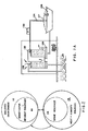
- Fig. 1 is an embodiment of the invention by which a brine dehumidifier according to the present invention is used to dehumidify the air in a greenhouse and to extract and store sensible heat from the air during the day, and to give back the sensible heat to the air during the night for the purpose of heating the greenhouse.
- regeneration of the brine is achieved on an annual basis using solar energy.
- Reference numeral 50 designates a greenhouse containing agricultural products 52 that produce water vapor during the day.
- Duct 54 contains brine dehumidifier 56 through which air in the greenhouse is recirculated by reason of the operation of fan 58.
- Dehumidifier 56 operates such that concentrated brine contained in a reservoir 60 is applied to the dehumidifier so that the brine and humid air come into direct contact.
- water vapor in the air in the greenhouse condenses on the brine diluting the same.
- the temperature of the concentrated brine entering the dehumidifier will be about 30 C; and in this case, the sensible heat from the brine is transferred to the air which is thus heated. About 5°C temperature drop of the brine will occur; and diluted brine, at about 25 C. is delivered to reservoir 60. Thus, at night, the brine will give up about the same amount of heat as was absorbed during the day.
- the concentration of the brine may be about 50%. After the winter season it would be diluted to about 30%. This difference in salinity represents the latent heat of condensation made available for heating during nights of the winter; and this heat must be restored to the brine in order to regenerate it. Regeneration is achieved during the summer.
- Reservoir 60 acts as an evaporator wherein the water vapor accumulated during the winter evaporates thereby concentrating the brine.
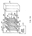
- Fig. 2 illustrates, in schematic form, apparatus for humidity and temperature control of an environment employing brine as the heat transfer medium in accordance with the present invention.
- the apparatus comprises a brine-vapor-air heat exchanger 110 disposed within enclosed environment 112, such as a room, greenhouse or vehicle, or in communication therewith.
- Brine is supplied to heat exchanger 110 from brine reservoir 114 which is associated with sources 116 and/or sinks of heat and/or humidity for governing the temperature and concentration of the brine supplied to the brine-vapor-air heat exchanger.
- the present invention involves a particular appreciation that, because the vapor pressure of the air/brine interface is lower than that of water at the same temperature, brine may be used to heat an environment while at the same time absorbing moisture therefrom.
- the condensation of moisture from the surrounding environment on the brine converts the latent heat of condensation to sensible heat and further heats the brine. Extremely efficient heating of an environment is thus provided in accordance with an embodiment of the present invention.
- reservoir 114 provides sufficient brine storage capacity to enable the brine to be concentrated by solar heat provided by diurnal temperature gradients over time in the ambient environment. These gradients may be relatively short term as between day and night, or between sun and shade, or alternatively they may be longer term, as between summer and winter.
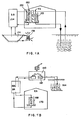
- Fig. 3A illustrates an embodiment of brine-vapor-air heat exchanger constructed and operative in accordance with another aspect of the present invention and comprising brine spray head 120 coupled to source of brine 124 which is coupled, in turn, to brine reservoir 126 which, typically, may be a solar evaporation pond.
- Removable covering 127 may be provided for protecting the pond from rain and resulting dilution of the brine stored therein. The cover also serves to retain heat in the brine when the brine is used for heating.
- air first passes through water spray 128, or is otherwise exposed to a source of water vapor such as produced by growing plants.
- the air then passes through a spray of brine provided by spray head 120.
- the brine spray falls by gravity in direct contact with the air to be treated and collects in receptacle 129.
- pump 130 may be provided to circulate the brine from the brine reservoir 126 through heat exchanger spray head 120.
- the brine reservoir may be located outside of the enclosed environment whose temperature and humidity it is desired to control. According to an alternative embodiment of the invention, the reservoir may be located within the enclosed environment.
- Water spray 128 may be supplied with water from any suitable source including, for example, warm water aquifer 131.
- water spray 128 may be replaced by any other source of water vapor, such as growing plants located within the enclosed atmosphere.
- the presence of a vapor source is important when the brine-vapor-air heat exchanger is being used in a heating mode because it provides vapor for condensation on the brine, thus releasing latent heat of condensation, which is converted into sensible heat as the temperature of the brine is raised.
- the heat sources maintaining the vapor sources at a constant temperature would be eliminated, insofar as possible, and the heat of evaporation would be removed as quickly as possible from the enclosure.
- FIG. 3B illustrates a different type of brine-vapor-air heat exchanger comprising a plurality of elongated falling brine film assemblies 132 operating adjacent an elongated falling water film assembly 133.
- Each of the falling film assemblies comprises a supply trough 134 and a receiving trough 135 and supply and drainage conduits 136 and 138.
- the brine or water falls from the supply troughs 134 through elongated slits formed in the bottom thereof in a generally planar film to the receiving troughs 135.
- a web of material such as woven jute, may be provided to define the film path and to enable relatively slow travel of the brine film therealong.
- any other material having capillary characteristics for slowing the brine flow under gravity may be used.
- the material may communicate with the top of supply trough 134 and thus eliminate the need for provision of slits in the bottom thereof.
- Pump 139 serves to circulate the brine as desired reservoir 140.
- Another pump 142 may be provided to circulate water from a vapor source such as a warm water aquifer 144 to assembly 133.
- the principle of operation of the apparatus of Fig. 3B is substantially similar to that of the apparatus of Fig.
- the water serving as the vapor source may be supplied at a temperature below the temperature of the environment, because the brine, having a lower vapor pressure than the water at the same temperature, acts as a heat pump in causing the vapor to evaporate on the brine, releasing the latent heat of condensation to the brine.
- the vapor source should provide water at 100 C. or more above ambient temperature.
- sufficient brine is provided for circulation through the heat exchanger such that the condensation heat capacity thereof is sufficient to provide desired heating over a period of time, say a season, without requiring other than seasonal concentration of the brine to restore its desired properties. It is also a particular feature of the invention that a brine reservoir of sufficient capacity is provided such that a sufficient quantity of brine at a desired temperature and concentration is available so that desired heat and humidity control can be effected without requiring the use of fossil fuels to reconstitute the brine (i.e., concentrate it).
- sufficient brine reservoir capacity is provided such that diurnal temperature gradients occurring naturally, such as day/night, sun/shade or seasonal temperature gradients can be used to reconstitute the brine.
- brine-vapor-air heat exchanger 150 comprises water and brine spray heads 152 and 153 arranged so as to define an air circulation path therepast such that the air travels parallel to the direction of the spray.
- Heat exchanger 150 is coupled to brine reservoir 154 which may comprise, or be connected to, solar evaporation pond 156.
- pond 156 comprises an open basic filled with brine and exposed to direct sunlight which causes heating and consequent evaporation of the brine.
- the rate of evaporation of the brine may be enhanced by circulation thereof through cooling tower 158.
- Such a cooling tower typically comprises apparatus for permitting the brine to contact air with a high surface area-to-volume ratio and may employ a brine spray.
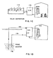
- flash evaporator and condenser 160 is employed for heating and concentrating brine in the presence of vapor source 162 coupled to a warm water reservoir 164.
- Condenser 160 is coupled to a brine reservoir 166 which in turn communicates with a brine-vapor-air heat exchanger 168 located within enclosure 170.
- Fig. 4C illustrates a solar distiller 172 for heating and concentrating brine supplied thereto from a brine reservoir 174.
- Fig. 4D illustrates an alternative embodiment of concentrated brine supply wherein brine aquifer 176 is employed as a virtually limitless supply of concentrated brine.
- the dilute brine is recycled from brine reservoir 177 to the aquifer via conduit 178, while concentrated brine is supplied to the reservoir via conduit 180.
- a reservoir may be located at the inlet to the brine evapartor, particularly where that evaporator is not in the form of a solar evaporation pond. It is a particular feature of the present invention that the reservoir or reservoirs and the overall brine supply should be of sufficient capacity to enable evaporation and cooling of the brine to be carried out primarily by naturally occurring temperature gradients.
Landscapes
- Engineering & Computer Science (AREA)
- Mechanical Engineering (AREA)
- General Engineering & Computer Science (AREA)
- Life Sciences & Earth Sciences (AREA)
- Environmental Sciences (AREA)
- Chemical & Material Sciences (AREA)
- Combustion & Propulsion (AREA)
- Heat Treatment Of Water, Waste Water Or Sewage (AREA)
- Greenhouses (AREA)
- Drying Of Gases (AREA)
- Other Air-Conditioning Systems (AREA)
Priority Applications (1)
| Application Number | Priority Date | Filing Date | Title |
|---|---|---|---|
| EP89119906A EP0361534B1 (en) | 1983-03-25 | 1984-03-26 | Means for controlling the condition of air in an enclosure |
Applications Claiming Priority (2)
| Application Number | Priority Date | Filing Date | Title |
|---|---|---|---|
| US06/479,009 US4819447A (en) | 1982-07-30 | 1983-03-25 | Method and means for controlling the condition of air in an enclosure |
| US479009 | 1983-03-25 |
Related Child Applications (1)
| Application Number | Title | Priority Date | Filing Date |
|---|---|---|---|
| EP89119906.9 Division-Into | 1989-10-26 |
Publications (2)
| Publication Number | Publication Date |
|---|---|
| EP0123447A1 EP0123447A1 (en) | 1984-10-31 |
| EP0123447B1 true EP0123447B1 (en) | 1991-05-15 |
Family
ID=23902279
Family Applications (2)
| Application Number | Title | Priority Date | Filing Date |
|---|---|---|---|
| EP84302023A Expired - Lifetime EP0123447B1 (en) | 1983-03-25 | 1984-03-26 | Method of and means for controlling the condition of air in an enclosure |
| EP89119906A Expired - Lifetime EP0361534B1 (en) | 1983-03-25 | 1984-03-26 | Means for controlling the condition of air in an enclosure |
Family Applications After (1)
| Application Number | Title | Priority Date | Filing Date |
|---|---|---|---|
| EP89119906A Expired - Lifetime EP0361534B1 (en) | 1983-03-25 | 1984-03-26 | Means for controlling the condition of air in an enclosure |
Country Status (6)
| Country | Link |
|---|---|
| US (1) | US4819447A (lt) |
| EP (2) | EP0123447B1 (lt) |
| JP (1) | JPS59210235A (lt) |
| CA (1) | CA1279539C (lt) |
| DE (3) | DE3486328D1 (lt) |
| ES (1) | ES8502838A1 (lt) |
Families Citing this family (16)
| Publication number | Priority date | Publication date | Assignee | Title |
|---|---|---|---|---|
| US4869070A (en) * | 1981-06-18 | 1989-09-26 | Geophysical Engineering Company | Method of and means for controlling the condition of air in an enclosure |
| US4841740A (en) * | 1982-07-30 | 1989-06-27 | Geophysical Engineering Company | Method of and means for controlling the condition of air in an enclosure |
| US5392611A (en) * | 1984-04-16 | 1995-02-28 | Geophysical Engineering Company | Method of and apparatus for reducing the heat load on a greenhouse |
| CA1305857C (en) * | 1985-09-26 | 1992-08-04 | Gad Assaf | Method of and means for controlling the condition of air in an enclosure |
| CA2015839A1 (en) * | 1989-05-11 | 1990-11-11 | Gad Assaf | Method of and apparatus for reducing the heat load on a greenhouse |
| US5109691A (en) * | 1989-12-08 | 1992-05-05 | Research Corporation Technologies, Inc. | Explosive detection screening system |
| FR2670359B1 (fr) * | 1990-12-18 | 1993-04-09 | Herteman Ets Paul | Procede et dispositif de chauffage de serres avec recuperateur de chaleur et enrichissement en gaz carbonique. |
| IL134196A (en) * | 2000-01-24 | 2003-06-24 | Agam Energy Systems Ltd | System for dehumidification of air in an enclosure |
| US10845067B2 (en) * | 2010-05-18 | 2020-11-24 | Energy & Enviornmental Research Center | Hygroscopic cooling tower for waste water disposal |
| US10808948B2 (en) | 2010-05-18 | 2020-10-20 | Energy & Environmental Research Center | Heat dissipation systems with hygroscopic working fluid |
| US10260761B2 (en) * | 2010-05-18 | 2019-04-16 | Energy & Environmental Research Center Foundation | Heat dissipation systems with hygroscopic working fluid |
| JP2013137187A (ja) * | 2011-11-30 | 2013-07-11 | Daiken:Kk | 水利用システム |
| NL2016574B1 (en) * | 2016-04-08 | 2017-11-02 | Hoeven J M Van Der Bv | Process to reduce the temperature of a feed of air and greenhouse. |
| WO2020076735A1 (en) * | 2018-10-08 | 2020-04-16 | Mjnn Llc | Control of latent and sensible loads in controlled environment agriculture |
| US11610158B2 (en) | 2019-05-02 | 2023-03-21 | Mjnn Llc | Automated placement of plant varieties for optimum performance within a grow space subject to environmental condition variability |
| WO2023193093A1 (en) * | 2022-04-05 | 2023-10-12 | Muclitech Inc. | Dehumidifier systems and assemblies |
Family Cites Families (8)
| Publication number | Priority date | Publication date | Assignee | Title |
|---|---|---|---|---|
| US1919781A (en) * | 1931-09-18 | 1933-07-25 | Henry O Forrest | Method and apparatus for conditioning air |
| US2405169A (en) * | 1942-07-06 | 1946-08-06 | Hoover Co | Refrigeration |
| US3247679A (en) * | 1964-10-08 | 1966-04-26 | Lithonia Lighting Inc | Integrated comfort conditioning system |
| US4164125A (en) * | 1977-10-17 | 1979-08-14 | Midland-Ross Corporation | Solar energy assisted air-conditioning apparatus and method |
| JPS5470940A (en) * | 1977-11-10 | 1979-06-07 | Yoshitane Kurimoto | Greenhouse apparatus |
| US4197714A (en) * | 1978-06-05 | 1980-04-15 | Schweitzer Industrial Corporation | System and method for liquid absorption air conditioning |
| US4259849A (en) * | 1979-02-15 | 1981-04-07 | Midland-Ross Corporation | Chemical dehumidification system which utilizes a refrigeration unit for supplying energy to the system |
| GB2073911B (en) * | 1980-04-15 | 1984-02-15 | Agri Projects International Lt | System for the control of temperature and humidity within a greenhouse |
-
1983
- 1983-03-25 US US06/479,009 patent/US4819447A/en not_active Expired - Fee Related
-
1984
- 1984-03-23 CA CA000450355A patent/CA1279539C/en not_active Expired - Lifetime
- 1984-03-23 ES ES530941A patent/ES8502838A1/es not_active Expired
- 1984-03-24 JP JP59057178A patent/JPS59210235A/ja active Granted
- 1984-03-26 DE DE3486328T patent/DE3486328D1/de not_active Expired - Lifetime
- 1984-03-26 EP EP84302023A patent/EP0123447B1/en not_active Expired - Lifetime
- 1984-03-26 DE DE198484302023T patent/DE123447T1/de active Pending
- 1984-03-26 DE DE8484302023T patent/DE3484571D1/de not_active Expired - Lifetime
- 1984-03-26 EP EP89119906A patent/EP0361534B1/en not_active Expired - Lifetime
Also Published As
| Publication number | Publication date |
|---|---|
| EP0123447A1 (en) | 1984-10-31 |
| ES530941A0 (es) | 1985-02-01 |
| ES8502838A1 (es) | 1985-02-01 |
| CA1279539C (en) | 1991-01-29 |
| DE3486328D1 (de) | 1994-09-01 |
| DE3484571D1 (de) | 1991-06-20 |
| EP0361534A2 (en) | 1990-04-04 |
| JPS59210235A (ja) | 1984-11-28 |
| JPH0356375B2 (lt) | 1991-08-28 |
| US4819447A (en) | 1989-04-11 |
| EP0361534A3 (en) | 1990-05-09 |
| EP0361534B1 (en) | 1994-07-27 |
| DE123447T1 (de) | 1986-04-30 |
Similar Documents
| Publication | Publication Date | Title |
|---|---|---|
| US4707995A (en) | Apparatus and method for controlling temperature and humidity within an enclosure | |
| CA1196266A (en) | System of moisture and temperature conditioning air using a solar pond | |
| CA1279539C (en) | Method of and means for controlling the condition of air in an enclosure | |
| CN112639364B (zh) | 液体干燥剂冷却系统和方法 | |
| JP4972106B2 (ja) | 温室空気の除湿用装置と方法及び温度 | |
| US5392611A (en) | Method of and apparatus for reducing the heat load on a greenhouse | |
| US20110203174A1 (en) | Method and apparatus for extracting carbon dioxide from air | |
| JPH05153873A (ja) | 囲い内を空調する方法および手段 | |
| US4803846A (en) | Method of and means for controlling the condition of air in an enclosure | |
| JP6366456B2 (ja) | 園芸施設用エネルギー供給装置 | |
| US4981021A (en) | Heat exchanger, system, and method for using the same | |
| JPH0728615B2 (ja) | 温室へ供給する熱量を低減化する方法及び装置 | |
| US4461339A (en) | Method for increasing the temperature of gaseous inert carrier medium on taking useful heat from a storage medium storing heat by water sorption | |
| US5228303A (en) | Method of and means for controlling the condition of air in an enclosure | |
| US2220219A (en) | Regenerative cooling system | |
| US4745963A (en) | Heat exchanger and systems and methods for using the same | |
| US4995242A (en) | Method of and means for controlling the condition of air in an enclosure | |
| US5097895A (en) | Heat exchanger, system and method for using the same | |
| US4872315A (en) | Heat exchanger and systems and methods for using the same | |
| US5050390A (en) | Method of and means for controlling the condition of air in an enclosure | |
| US5020333A (en) | Method of and means for controlling the condition of air in an enclosure | |
| Souss et al. | Comprehensive Review on Climate Control and Cooling Systems in Greenhouses under Hot and Arid Conditions. Agronomy. 2022; 12: 626 | |
| Ryan | An air modification system to reduce winter ventilation rates in broiler houses | |
| Kubota et al. | Feasibility study for water recovery system for pad-and-fan cooled greenhouse in semiarid climate | |
| Daunicht | Problems of desert greenhouses |
Legal Events
| Date | Code | Title | Description |
|---|---|---|---|
| PUAI | Public reference made under article 153(3) epc to a published international application that has entered the european phase |
Free format text: ORIGINAL CODE: 0009012 |
|
| AK | Designated contracting states |
Kind code of ref document: A1 Designated state(s): BE DE FR GB IT NL Designated state(s): BE DE FR GB IT NL |
|
| 17P | Request for examination filed |
Effective date: 19850430 |
|
| ITCL | It: translation for ep claims filed |
Representative=s name: BUGNION S.P.A. |
|
| TCNL | Nl: translation of patent claims filed | ||
| EL | Fr: translation of claims filed | ||
| DET | De: translation of patent claims | ||
| 17Q | First examination report despatched |
Effective date: 19860409 |
|
| R17C | First examination report despatched (corrected) |
Effective date: 19870430 |
|
| DIN1 | Information on inventor provided before grant (deleted) | ||
| GRAA | (expected) grant |
Free format text: ORIGINAL CODE: 0009210 |
|
| RAP1 | Party data changed (applicant data changed or rights of an application transferred) |
Owner name: GEOPHYSICAL ENGINEERING COMPANY |
|
| RIN1 | Information on inventor provided before grant (corrected) |
Inventor name: ASSAF, GAD |
|
| AK | Designated contracting states |
Kind code of ref document: B1 Designated state(s): BE DE FR GB IT NL |
|
| PG25 | Lapsed in a contracting state [announced via postgrant information from national office to epo] |
Ref country code: NL Effective date: 19910515 Ref country code: BE Effective date: 19910515 |
|
| XX | Miscellaneous (additional remarks) |
Free format text: TEILANMELDUNG 89119906.9 EINGEREICHT AM 26/03/84. |
|
| REF | Corresponds to: |
Ref document number: 3484571 Country of ref document: DE Date of ref document: 19910620 |
|
| ITF | It: translation for a ep patent filed | ||
| EN | Fr: translation not filed | ||
| PG25 | Lapsed in a contracting state [announced via postgrant information from national office to epo] |
Ref country code: FR Effective date: 19911004 |
|
| NLV1 | Nl: lapsed or annulled due to failure to fulfill the requirements of art. 29p and 29m of the patents act | ||
| PGFP | Annual fee paid to national office [announced via postgrant information from national office to epo] |
Ref country code: GB Payment date: 19920316 Year of fee payment: 9 |
|
| PLBE | No opposition filed within time limit |
Free format text: ORIGINAL CODE: 0009261 |
|
| STAA | Information on the status of an ep patent application or granted ep patent |
Free format text: STATUS: NO OPPOSITION FILED WITHIN TIME LIMIT |
|
| 26N | No opposition filed | ||
| PG25 | Lapsed in a contracting state [announced via postgrant information from national office to epo] |
Ref country code: DE Effective date: 19921201 |
|
| REG | Reference to a national code |
Ref country code: FR Ref legal event code: ST |
|
| PG25 | Lapsed in a contracting state [announced via postgrant information from national office to epo] |
Ref country code: GB Effective date: 19930326 |
|
| GBPC | Gb: european patent ceased through non-payment of renewal fee |
Effective date: 19930326 |