EP0123010A1 - Batterie primaire - Google Patents
Batterie primaire Download PDFInfo
- Publication number
- EP0123010A1 EP0123010A1 EP84100014A EP84100014A EP0123010A1 EP 0123010 A1 EP0123010 A1 EP 0123010A1 EP 84100014 A EP84100014 A EP 84100014A EP 84100014 A EP84100014 A EP 84100014A EP 0123010 A1 EP0123010 A1 EP 0123010A1
- Authority
- EP
- European Patent Office
- Prior art keywords
- metal
- housing
- electrode structures
- thicknesses
- terminal
- Prior art date
- Legal status (The legal status is an assumption and is not a legal conclusion. Google has not performed a legal analysis and makes no representation as to the accuracy of the status listed.)
- Withdrawn
Links
Images
Classifications
-
- H—ELECTRICITY
- H01—ELECTRIC ELEMENTS
- H01M—PROCESSES OR MEANS, e.g. BATTERIES, FOR THE DIRECT CONVERSION OF CHEMICAL ENERGY INTO ELECTRICAL ENERGY
- H01M6/00—Primary cells; Manufacture thereof
- H01M6/14—Cells with non-aqueous electrolyte
-
- H—ELECTRICITY
- H01—ELECTRIC ELEMENTS
- H01M—PROCESSES OR MEANS, e.g. BATTERIES, FOR THE DIRECT CONVERSION OF CHEMICAL ENERGY INTO ELECTRICAL ENERGY
- H01M6/00—Primary cells; Manufacture thereof
- H01M6/42—Grouping of primary cells into batteries
- H01M6/46—Grouping of primary cells into batteries of flat cells
Definitions
- the present invention relates to an electrochemical cell and, more particularly, to a primary electrochemical cell capable of selective operation at one or more of several possible discharge rates.
- a single primary electrochemical cell such as a cylindrical electrochemical cell, which is capable of operating at one of several different discharge rates. It may also be a requirement that the cell operate at very low temperatures, for example, down to -40°C.
- a typical application for a cell of the above character might utilize the different values of output voltages corresponding to the different discharge rates to power one or more loads on a selective basis.
- Electrochemical cells capable of high-rate (greater than lmA/cm 2 ), low temperature (to -40°C) operation have been described in detail in U.S. Patent No. 4,284,691, in the names of Franz Goebel and William T. McHugh, and in U.S. Patent No. 4,309,819, in the name of Franz Goebel.
- a cylindrical electrochemical cell is described including a battery stack disposed within a cylindrical metal housing of the cell together with an electrolytic solution.
- the battery stack comprises a large number of generally circular, annular-shaped electrode components superimposed on each other in a single vertical stacked array relative to the housing and relative to a central, elongated, cylindrical, metal terminal member which extends completely through the battery stack and is encircled by the battery stack components.
- the components of the battery stack include a plurality of anode structures and a plurality of carbon current electrode/ separator assemblies. arranged in the array in alternation with the anode structures.
- Each of the anode structures includes a metal disc, for example, of lithium, and a contact member secured to the disc and_ in physical and electrical contact with both the disc and the central terminal member.
- Each of the carbon current collector electrode/separator assemblies includes a pair of carbon/fiberglass cathode structures physically adjacent to opposite sides of a metal (e.g., nickel) current collector disc. These latter components have central openings of a size to space, or electrically isolate, the components from the central terminal member.
- the current collector disc is of a size and configuration so as to make direct physical and electrical contact with the interior wall of the housing of the cell.
- electrochemical cells as briefly described hereinabove and in the aforementioned patents are highly suitable for a wide range of applications requiring high-current drain, low-temperature operation.
- each of the cells as described in the patents is capable of operating within a narrow range of discharge rates.
- a cell as described in the aforementioned patents does not satisfy this requirement.
- an electrochemical cell which offers capabilities lacking in prior art electrochemical cells as described hereinabove.
- the electrochemical cell in accordance with the present invention includes an elongated metal housing and an electrochemical system contained within the housing.
- the electrochemical system includes an electrolytic solution and a plurality of battery stack components exposed to the electrolytic solution and arranged in first and second battery stacks.
- the first and second battery stacks are arranged to respectively encircle first and second spaced-apart elongated metal terminals provided within and along the direction of the housing. The two stacks and their associated metal terminals are spaced apart from each other within the housing.
- the first battery stack as utilized within the cell comprises a first plurality of metal electrode structures and a first plurality of carbon electrode structures.
- the first plurality of metal electrode structures are of first thicknesses and are in direct physical contact with the first elongated metal terminal and spaced from an interior wall of the housing:
- the first plurality of carbon electrode structures are of first thicknesses and are arranged in alternation with the first plurality of metal electrode structures. These carbon electrode structures are in direct physi - cal contact with the interior wall of the housing and are spaced from the first elongated metal terminal,
- the second battery stack as utilized within the cell comprises a second plurality of metal electrode structures and a second plurality of carbon electrode structures.
- the second plurality of metal electrode structures are of second thicknesses and are in direct physical contact with the second elongated metal terminal and spaced from the interior wall of the housing.
- the second plurality of carbon electrode structures are of second thicknesses and are arranged in alternation with the second plurality of metal electrode structures. These carbon electrode structures are in direct physical contact with the interior wall of the housing and are spaced from the second elongated metal terminal.
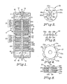
- the electrochemical cell 1 as shown in FIG. 1 generally includes an elongated, cylindrical metal case or housing 2, for example, of stainless steel, within which a pair of battery stacks 3 and 4 are disposed, one above the other, and insulated from each other at a central region by a suitable porous insulator 5, for example, of glass fiber or plastic.
- the housing 2 of the cell 1 further includes an electrolytic solution 6 in contact with the battery stacks 3 and 4.
- the electrolytic solution 6 may include a reducible soluble cathode such as thionyl chloride and an electrolyte solute such as lithium tetrachloroaluminate dissolved in the thionyl chloride.
- Each of the battery stacks 3 and 4 comprises a large number of generally circular, annular-shaped electrode components superimposed on each other in a vertical stacked array as shown in FIG. 1.
- a similar terminal member 8 extends completely and centrally through the battery stack 4 and is surrounded by the electrode components of that stack.
- the electrode components of the two stacks 3 and 4 are retained in position by corresponding pairs of spaced-apart retainer plates 9 and 10, respectively, which are secured to opposing end regions of the respective terminal members 7 and 8 on opposite sides of the respective battery stacks 3 and 4.
- the retainer plates 9 and 10 are preferably of metal and may be secured to the terminal members in any suitable manner, as by welding.
- the diameters of the metal retaining plates are selected to be smaller than the internal diameter of the housing 2 so as to be electrically isolated from the housing 2. If the retainer plates 9 and 10 are of a material other than metal, for example, an electrically-nonconductive material such as plastic, the aforementioned insulator 5 between the stacks is unnecessary and the retainer plates may make direct (e.g., frictional) physical contact with the interior wall of the housing 2. In this case, however, the retainer plates should have openings therein (or otherwise be porous) for permitting bi-directional passage of the electrolytic solution 6 between the two portions of the housing 2 in which the battery stacks 3 and 4 are located.
- the terminal members 7 and 8 as discussed hereinabove are connected at their outer exposed ends by respective metal jumper strips 11 and 12 to respective cylindrical, metal hollow feedthrough members 13 and 14.
- the metal jumper strips 11 and 12, which may be of nickel, are typically connected to, and between, the terminal members 7 and 8 and the feedthrough members 13 and 14 by spot welds.
- the feedthrough members 13 and 14 are insulated from respective hermetically-sealed end caps 15 and 16 of the cell 1 by way of respective standard glass or ceramic-to- metal seals 17 and 18.
- the terminal member 7, the jumper strip 11 and the feedthrough member 13 collectively represent a first negative electrical terminal of the cell l, and, likewise, the terminal member 8, the jumper strip 12 and the feedthrough member 14 collectively represent a second negative electrical terminal of the cell 1.
- the metal housing 2 of the cell 1 serves as a common positive electrical terminal of the cell 1.
- the battery stack 3 as mentioned hereinabove comprises a plurality of anode structures 20 and a plurality of carbon current collector cathode/separator assemblies 21 arranged in alternation with the anode structures 20.
- the battery stack 4 comprises a plurality of anode structures 22 and a plurality of carbon current collector cathode/separator assemblies 23 arranged in alternation with the anode structures 22.
- the components of the two stacks 3 and 4 differ from each other principally in that the anode structures 20 of the stack 3 are thinner than the anode structures 22 of the stack 4 and, similarly, the carbon current collector cathode/separator assemblies 21 of the stack 3 are thinner than the cathode/separator assemblies 23 of the stack 4.
- the effect of the use in the stacks 3 and 4 of the anode structures and cathode/separator assemblies of different thicknesses is to provide a greater total surface area, and a consequential greater current drain capability (during discharge), for the stack 3 than for the stack 4.
- Typical values of thicknesses for the anode structures 20 and 22 are 0.01 inch and 0.06 inch, respectively, and typical values of thicknesses for the cathode/ separator assemblies 21 and 23 are 0.02 inch and 0.10 inch, respectively.
- the diameters of the two anode structures 20 and 22 are the same and, similarly, the diameters of the two cathode/separator assemblies 21 and 23 are the same.
- the total number of electrode components in each of the stacks 3 or 4 is selected so as to achieve the desired time periods or durations of current drain for each of the stacks 3 and 4 during discharge of the cell 1, as will be explained more fully hereinafter.
- FIGS. 2 and 3 illustrate the details of one of the anode structures 20 as employed in the stack 3, and FIGS.
- FIG. 4 and 5 illustrate the details of one of the cathode/ separator assemblies 21 as employed in the stack 3:
- the following discussion of the anode structure 20 and the cathode/separator assembly 21 also applies, but for the differences noted hereinabove, to the anode structures 22 and the cathode/separator assemblies 23 as used in the stack 4.
- similar referencing nomenclature is used in FIG. 1 for the anode structures 22 and the cathode/separator assemblies 23 as used with the anode structure 20 shown in FIGS. 2 and 3 and the cathode/separator assembly 21 shown in FIGS. 4 and 5.
- each of the anode structures 20 comprises a flat, generally circular annular-shaped disc 20a, and a small cross-shaped contact member 20b secured to the disc 20a.
- a suitable material for the disc 20a for use within the cell 1 is an active oxidizable alkali metal, such as lithium, and a suitable thickness therefor is 0.01 inch.
- the cross-shaped contact member 20b which may be of nickel of a thickness of 0.003 inch, is secured to the lithium anode disc 20a by means of several small tines or barbs 20c which are stamped into the arms thereof and which "bite" into the soft lithium metal for making physical and electrical contact therewith.
- the contact member 20b further has a plurality of resilient portions 20d which collectively define a cross-shaped opening 20e in the contact member 20b. This opening is aligned with a large central opening 20f (FIG. 3) in the -lithium anode disc 20a.
- the opening 20e in the contact member 20b has a size as defined by the portions 20d so that the anode structure 20 can be assembled onto the associated terminal member 7 (which may have a diameter of 0.125 inch) by simply forcing the anode structure 20 over the top end of the terminal member 7 and sliding the anode structure 20 along the terminal member 7 to its proper position in the battery stack 3. When in its proper position in the stack, and as indicated in FIG.
- the resilient portions 20d of the contact member 20b are deflected upwardly slightly and make direct physical and electrical contact with the terminal member 7.
- the sharp edges of the portions 20d bite into the terminal member 7 so as to secure the anode structure 20 in position.
- the diameter of each anode structure 20 is selected to be smaller than the internal diameter of the housing 2 of the cell 1 so as to prevent the anode structure 20 from making physical and electrical contact with the interior wall of the housing 2.
- a suitable diameter for the anode structure 20 is 0.90 inch.
- a typical internal diameter for the housing 2, corresponding to a C-size cell, is one inch.
- Corresponding thickness dimensions for the anode structures 22 of the battery stack 4 are a thickness of 0.06 inch for the lithium anode discs 22a and 0.003 inch for the contact member 22b.
- Each of the aforementioned carbon current collector cathode/separator assemblies 21 as shown in FIGS. 4 and 5 generally includes a circular, notched metal current collector substrate 21a, and a pair of integrated carbon/insulator structures 21b on opposite sides of the current collector substrate 21a.
- the integrated carbon/insulator structures 21b as shown in FIGS. 4 and 5 are not secured to the current collector substrate 21a but rather are only in direct physical contact with the substrate 21a when assembled into the cell l.
- the current collector substrate 21a as employed in the cell 1 and shown in FIGS. 4 and 5 takes the form of a circular, flat disc of a metal such as nickel having a central opening 21c (FIG.
- the opening 21c in the substrate 21a is of a diameter greater than the diameter of the associated terminal member 7 so as to establish a spacing, and to be electrically isolated from, the terminal member 7 when the substrate 21a and the associated carbon/insulator structures 21b are assembled together into the cell 1.
- the notches 21d serve to establish multiple passageways by which the electrolytic solution 6 is able quickly and readily to fill void spaces in the cell and permeate porous components of the battery stack 3.
- the notches 21d enable the peripheral portions 2le to be deflected upwardly during assembly of the cell 1 whereby sharp edges of the portions 2le are able to bite into the interior wall of the housing 2 and, as indicated in FIG. 1, make direct physical and electrical contact with the wall of the housing 2 in numerous places.
- the diameter of the substrate 21a prior to insertion into the housing 2 is slightly greater than the internal diameter of the housing 2 so as to permit upward deflection of the arcuate portions 2le when the substrate 2la is inserted into the housing 2 .
- Each of the carbon/insulator structures 21b used with the above-described current collector substrate 21a comprises, as shown in FIG. 5, an arrangement of a porous insulator sheet or disc 21f physically and permanently integrated with a porous carbon layer or disc 21g.
- the porous insulator disc 21f is of an electrically-nonconductive material such as glass fiber and serves as a separator for electrically isolating the associated porous carbon disc 21g from an immediately adjacent one of the lithium anode structures 20.
- the porous carbon disc or layer 21g comprises an aggregation of porous globules or conglomerates containing carbon black and a binder such as "Teflon" and having a network of electrolyte-conducting channels formed throughout its entire mass for permitting the electrolytic solution 6 to permeate the layer 21g and the associated insulator disc 21f.
- the porous insulator disc 21f and the porous carbon layer 21g have respective circular central openings 21h and 21i of the same size as, and aligned with, the opening 21c in the current collector substrate 21 for providing a space between these elements and the terminal member 7 when assembled within the cell l.
- the carbon/insulator structure 21b as described hereinabove is also described in detail, and claimed, in U.S. Patent No. 4,296,187, in the names of John E. Barnes, Franz Goebel, and William T. McHugh.
- the current collector substrate 21a as described hereinabove is also described in detail, and claimed, in U.S. Patent No. 4,315,060, in the names of Franz Goebel and William T. McHugh.
- Suitable thicknesses for the porous insulator disc 21f and the porous carbon layers 2lg are 0.005 inch and 0.01 inch, respectively.
- a suitable thickness for the current collector substrate 21a is 0.003 inch.
- Suitable corresponding thickness dimensions for the cathode/ separator assemblies 23 of the stack 4 are a thickness of 0.005 inch for the porous insulator discs 23f, a thickness of 0.05 inch for the porous carbon layers 23g, and a thickness of 0.003 inch for the current collector substrates 23a. From a comparison of the dimensions of the two types of cathode/separator assemblies 21 and 23, it wil-1 be noted that the current collector substrates 21a and 23a of the two cathode/separator assemblies are of the same thickness, and the porous insulator discs 21f and 23f are also of the same thickness.
- the electrolytic solution 6 which is introduced into the cell 1 by way of either one of the feedthrough members 13 and 14, is readily able to diffuse the stack and permeate the porous components thereof. This latter action is facilitated by the aforedescribed numerous peripheral notches formed in the current collector substrates 21a and 23a and adjacent to the interior wall of the housing 2 and also by the spaces established between the components of the stacks and the interior wall of the housing 2 and the terminal members 7 and 8.
- the electrolytic solution 6 diffuses into the multiple carbon discs 21g and 23g by way of the network of electrolyte-conducting channels formed therein and also diffuses into the multiple porous insulator discs 21f and 23f.
- the cell 1 as described hereinabove is capable of operation at any one of three possible discharge rates.
- a load (not shown) is connected between the negative terminal (feedthrough) member 14 and the housing 2 (positive terminal)
- the cell 1 will discharge at a first rate and produce a first set of values of current drain and output voltage
- the load is connected between the negative terminal (feedthrough) member 13 and the housing 2
- the cell 1 will discharge at a second, higher, rate and produce a second, higher, set of values of current drain and output voltage
- the terminal members 13 and 14 are shorted together and the load is connected between both terminal members 13 and 14 and the housing 2, the cell 1 will discharge at a third rate and produce a third, and highest, set of values of current drain and output voltage.
- the three different rates of discharge of the cell 1 are determined by the total surface areas of the two battery stacks 3 and 4 which, in turn, are determined by the number and thicknesses of the anode structures (20 and 22) and cathode/separator assemblies (21 and 23) used in the stacks 3 and 4.
- this stack will discharge at a higher rate and produce a greater current drain and output voltage than the stack 4 which contains the thicker components.
- the durations of the possible discharge operations are determined by, and directly proportional to, the number of components used in the stacks 3 and 4.
- the reducible soluble cathode in the electrolytic solution 6, namely, the thionyl chloride is catalytically reduced at the surfaces of the multiple carbon discs of either one or both of the stacks 3 and 4 (depending on the selected mode of operation), and the lithium metal of the anode structures of either one or both of the stacks 3 and 4 is gradually and progressively depleted, starting from the outside edges of the anode structures and progressing toward the centers of the anode structures.
- the cell 1 is capable of satisfactory performance down to a temperature as low as -40 0 C.
- the cell 1 may also be used with several loads, selectively connected to the cell in any suitable manner.
Landscapes
- Engineering & Computer Science (AREA)
- Manufacturing & Machinery (AREA)
- Chemical & Material Sciences (AREA)
- Chemical Kinetics & Catalysis (AREA)
- Electrochemistry (AREA)
- General Chemical & Material Sciences (AREA)
- Primary Cells (AREA)
- Battery Electrode And Active Subsutance (AREA)
Applications Claiming Priority (2)
| Application Number | Priority Date | Filing Date | Title |
|---|---|---|---|
| US06/455,090 US4447504A (en) | 1983-01-03 | 1983-01-03 | Electrochemical cell with two rate battery stacks |
| US455090 | 1983-01-03 |
Publications (1)
| Publication Number | Publication Date |
|---|---|
| EP0123010A1 true EP0123010A1 (fr) | 1984-10-31 |
Family
ID=23807362
Family Applications (1)
| Application Number | Title | Priority Date | Filing Date |
|---|---|---|---|
| EP84100014A Withdrawn EP0123010A1 (fr) | 1983-01-03 | 1984-01-02 | Batterie primaire |
Country Status (4)
| Country | Link |
|---|---|
| US (1) | US4447504A (fr) |
| EP (1) | EP0123010A1 (fr) |
| JP (1) | JPS59157964A (fr) |
| DK (1) | DK1184A (fr) |
Families Citing this family (28)
| Publication number | Priority date | Publication date | Assignee | Title |
|---|---|---|---|---|
| DE3633385A1 (de) * | 1986-10-01 | 1988-04-14 | Silberkraft Leichtakku | Galvanische zelle mit einer aus alkali- oder erdalkalimetallen bestehenden loeslichen elektrode |
| US5204610A (en) * | 1991-02-15 | 1993-04-20 | Globe-Union, Inc. | Long lived dual battery with automatic latching switch |
| US5223351A (en) * | 1991-11-14 | 1993-06-29 | Globe-Union Inc. | Dual battery system |
| US5455638A (en) * | 1993-09-10 | 1995-10-03 | Comdisco, Inc. | Electrochromic eyewear |
| US5900720A (en) * | 1993-09-10 | 1999-05-04 | Kallman; William R. | Micro-electronic power supply for electrochromic eyewear |
| US5455637A (en) * | 1993-09-10 | 1995-10-03 | Comdisco, Inc. | Electrochromic eyewear system, rechargeable eyewear and external charger therefor |
| US5835185A (en) * | 1993-09-10 | 1998-11-10 | Kallman; William R. | Spring-hinged frame for eyeware |
| US5993983C1 (en) * | 1997-03-14 | 2001-09-18 | Century Mfg Co | Portable power supply using hybrid battery technology |
| US6677077B2 (en) | 1997-04-04 | 2004-01-13 | Wilson Greatbatch Ltd. | Electrochemical cell having multiplate electrodes with differing discharge rate regions |
| US5935728A (en) * | 1997-04-04 | 1999-08-10 | Wilson Greatbatch Ltd. | Electrochemical cell having multiplate and jellyroll electrodes with differing discharge rate regions |
| US5935724A (en) | 1997-04-04 | 1999-08-10 | Wilson Greatbatch Ltd. | Electrochemical cell having multiplate electrodes with differing discharge rate regions |
| US6451463B1 (en) * | 1997-10-06 | 2002-09-17 | Reveo, Inc. | Electro-chemical power generation systems employing arrays of electronically-controllable discharging and/or recharging cells within a unity support structure |
| US6623884B1 (en) | 2000-08-07 | 2003-09-23 | Wilson Greatbatch Ltd. | Electrochemical lithium ion secondary cell having multiplate and jellyroll electrodes with differing discharge rate regions |
| US6541140B1 (en) | 2000-08-07 | 2003-04-01 | Wilson Greatbatch Technologies, Inc. | Electrochemical lithium ion secondary cell having multiplate electrodes with differing discharge rate regions |
| CA2419108A1 (fr) * | 2000-08-10 | 2002-02-21 | University Of Virginia Patent Foundation | Batterie multifonction et son procede de fabrication |
| TW200830609A (en) * | 2007-01-04 | 2008-07-16 | Wen-Chin Shiau | Double-side usable modularized battery case |
| US8309259B2 (en) | 2008-05-19 | 2012-11-13 | Arizona Board Of Regents For And On Behalf Of Arizona State University | Electrochemical cell, and particularly a cell with electrodeposited fuel |
| PL2309954T3 (pl) * | 2008-07-30 | 2015-03-31 | Dtamedical | Urządzenie do zabiegów, złożone z obudowy wykonanej z co najmniej dwóch komplementarnych części |
| WO2011035176A1 (fr) * | 2009-09-18 | 2011-03-24 | Fluidic, Inc. | Système de pile électrochimique rechargeable avec une commutation de mode de charge et de décharge d'une électrode de charge dans les piles |
| MX2012004237A (es) * | 2009-10-08 | 2012-10-03 | Fluidic Inc | Celda metalica-aire recargable con sistema de manejo de flujo. |
| CN102544638B (zh) | 2010-06-24 | 2015-07-15 | 流体股份有限公司 | 具有阶梯形支架燃料阳极的电化学电池 |
| CN102403525B (zh) | 2010-09-16 | 2016-02-03 | 流体公司 | 具有渐进析氧电极/燃料电极的电化学电池系统 |
| US9105946B2 (en) | 2010-10-20 | 2015-08-11 | Fluidic, Inc. | Battery resetting process for scaffold fuel electrode |
| JP5908251B2 (ja) | 2010-11-17 | 2016-04-26 | フルイディック,インク.Fluidic,Inc. | 階層型アノードのマルチモード充電 |
| JP5514971B2 (ja) * | 2012-01-29 | 2014-06-04 | エクセルギー・パワー・システムズ株式会社 | 積層電池および積層電池システム |
| KR101684365B1 (ko) * | 2014-08-21 | 2016-12-08 | 주식회사 엘지화학 | 수직 적층 구조의 전지셀 |
| JP2019521497A (ja) | 2016-07-22 | 2019-07-25 | ナントエナジー,インク. | 電気化学セル内の水分及び二酸化炭素管理システム |
| US11251476B2 (en) | 2019-05-10 | 2022-02-15 | Form Energy, Inc. | Nested annular metal-air cell and systems containing same |
Citations (6)
| Publication number | Priority date | Publication date | Assignee | Title |
|---|---|---|---|---|
| US2212054A (en) * | 1939-09-25 | 1940-08-20 | Arthur E Spicer | Multiple cell battery |
| US2379374A (en) * | 1943-03-17 | 1945-06-26 | Paul D Payne | Manufacture of electric storage cells |
| GB678847A (en) * | 1950-05-04 | 1952-09-10 | Nat Res Dev | Improvements relating to electric batteries |
| US3242009A (en) * | 1961-11-21 | 1966-03-22 | Gen Motors Corp | Battery |
| US4169920A (en) * | 1978-12-11 | 1979-10-02 | Gte Laboratories Incorporated | Hermetically sealed electrochemical battery |
| WO1981003719A1 (fr) * | 1980-06-13 | 1981-12-24 | Gte Prod Corp | Procede d'assemblage d'une cellule electrochimique |
Family Cites Families (5)
| Publication number | Priority date | Publication date | Assignee | Title |
|---|---|---|---|---|
| US2616937A (en) * | 1949-05-25 | 1952-11-04 | Svenska Ackumulator Ab | Alkaline accumulator |
| US2798895A (en) * | 1954-06-18 | 1957-07-09 | Ray O Vac Co | Point contact battery |
| US3200014A (en) * | 1962-02-14 | 1965-08-10 | Roberts Alan King | Auxiliary battery arrangement |
| US3347709A (en) * | 1964-02-27 | 1967-10-17 | Burndept Ltd | Layer type battery having both terminals at one end |
| US4283470A (en) * | 1980-06-13 | 1981-08-11 | Gte Products Corporation | Anode structure for an electrochemical cell |
-
1983
- 1983-01-03 US US06/455,090 patent/US4447504A/en not_active Expired - Fee Related
- 1983-12-29 JP JP58252292A patent/JPS59157964A/ja active Pending
-
1984
- 1984-01-02 EP EP84100014A patent/EP0123010A1/fr not_active Withdrawn
- 1984-01-02 DK DK1184A patent/DK1184A/da not_active Application Discontinuation
Patent Citations (6)
| Publication number | Priority date | Publication date | Assignee | Title |
|---|---|---|---|---|
| US2212054A (en) * | 1939-09-25 | 1940-08-20 | Arthur E Spicer | Multiple cell battery |
| US2379374A (en) * | 1943-03-17 | 1945-06-26 | Paul D Payne | Manufacture of electric storage cells |
| GB678847A (en) * | 1950-05-04 | 1952-09-10 | Nat Res Dev | Improvements relating to electric batteries |
| US3242009A (en) * | 1961-11-21 | 1966-03-22 | Gen Motors Corp | Battery |
| US4169920A (en) * | 1978-12-11 | 1979-10-02 | Gte Laboratories Incorporated | Hermetically sealed electrochemical battery |
| WO1981003719A1 (fr) * | 1980-06-13 | 1981-12-24 | Gte Prod Corp | Procede d'assemblage d'une cellule electrochimique |
Also Published As
| Publication number | Publication date |
|---|---|
| DK1184D0 (da) | 1984-01-02 |
| DK1184A (da) | 1984-07-04 |
| JPS59157964A (ja) | 1984-09-07 |
| US4447504A (en) | 1984-05-08 |
Similar Documents
| Publication | Publication Date | Title |
|---|---|---|
| US4447504A (en) | Electrochemical cell with two rate battery stacks | |
| US4731305A (en) | Cylindrical bipolar electrode battery | |
| US4283470A (en) | Anode structure for an electrochemical cell | |
| US4539274A (en) | Electrochemical cell having wound electrode structures | |
| US4284691A (en) | Electrochemical cell | |
| US4315060A (en) | Metal substrate for an electrochemical cell | |
| US4539273A (en) | Electrode structure for electrochemical cell | |
| US4347293A (en) | Electrochemical cell | |
| US4309817A (en) | Method for assembling an electrochemical cell | |
| US4743520A (en) | Self-limiting electrochemical cell | |
| EP0163062A2 (fr) | Construction pour batteries électrochimiques | |
| US4309819A (en) | Method for assembling an electrochemical cell | |
| US4471035A (en) | Electrochemical battery | |
| US4369237A (en) | Multi-element anode structures for electrochemical cells | |
| US4731308A (en) | Battery component | |
| US4372038A (en) | Method for assembling an electrochemical cell | |
| US4410608A (en) | Electrochemical cell | |
| US4355085A (en) | Electrochemical cell | |
| US4672011A (en) | Electrochemical cell having coupling members with radial channels | |
| US4405694A (en) | Electrochemical cell | |
| US4668592A (en) | Electrochemical cell having porous metal coupling members |
Legal Events
| Date | Code | Title | Description |
|---|---|---|---|
| PUAI | Public reference made under article 153(3) epc to a published international application that has entered the european phase |
Free format text: ORIGINAL CODE: 0009012 |
|
| 17P | Request for examination filed |
Effective date: 19840125 |
|
| AK | Designated contracting states |
Designated state(s): DE FR GB |
|
| STAA | Information on the status of an ep patent application or granted ep patent |
Free format text: STATUS: THE APPLICATION HAS BEEN WITHDRAWN |
|
| 18W | Application withdrawn |
Withdrawal date: 19860219 |
|
| RIN1 | Information on inventor provided before grant (corrected) |
Inventor name: GOEBEL, FRANZ |