EP0122942A1 - Wrist mechanism for industrial robot - Google Patents
Wrist mechanism for industrial robot Download PDFInfo
- Publication number
- EP0122942A1 EP0122942A1 EP83903401A EP83903401A EP0122942A1 EP 0122942 A1 EP0122942 A1 EP 0122942A1 EP 83903401 A EP83903401 A EP 83903401A EP 83903401 A EP83903401 A EP 83903401A EP 0122942 A1 EP0122942 A1 EP 0122942A1
- Authority
- EP
- European Patent Office
- Prior art keywords
- motion
- wrist
- industrial robot
- axis
- robot
- Prior art date
- Legal status (The legal status is an assumption and is not a legal conclusion. Google has not performed a legal analysis and makes no representation as to the accuracy of the status listed.)
- Withdrawn
Links
Images


Classifications
-
- B—PERFORMING OPERATIONS; TRANSPORTING
- B25—HAND TOOLS; PORTABLE POWER-DRIVEN TOOLS; MANIPULATORS
- B25J—MANIPULATORS; CHAMBERS PROVIDED WITH MANIPULATION DEVICES
- B25J17/00—Joints
- B25J17/02—Wrist joints
- B25J17/0283—Three-dimensional joints
-
- B—PERFORMING OPERATIONS; TRANSPORTING
- B25—HAND TOOLS; PORTABLE POWER-DRIVEN TOOLS; MANIPULATORS
- B25J—MANIPULATORS; CHAMBERS PROVIDED WITH MANIPULATION DEVICES
- B25J9/00—Programme-controlled manipulators
- B25J9/10—Programme-controlled manipulators characterised by positioning means for manipulator elements
- B25J9/1005—Programme-controlled manipulators characterised by positioning means for manipulator elements comprising adjusting means
- B25J9/101—Programme-controlled manipulators characterised by positioning means for manipulator elements comprising adjusting means using limit-switches, -stops
Abstract
A wrist mechanism for an industrial robot includes an industrial robot wrist (30) provided at the free end of a robot arm (20) and which has two degrees of freedom, i.e., an oscillating motion and a swivel motion about two substantially orthogonal axes. The robotwrist (30) is adapted to effect a 90° change in motion direction by a bevel gear mechanism (96) provided in either one of two mechanisms (80,82,90,92, 96) for transmitting the oscillating motion and the swivel motion, respectively, and means (110a, 110b, 120a, 120b) for detecting any overtravel in both the motions, and means (112a, 112b, 122a, 122b) for detecting the home positions of both the motions are coaxially disposed on one of the two orthogonal axes.
Description
- The present invention relates to a wrist mechanism of an industrial robot and, more particularly, to a wrist mechanism of an industrial robot, having at least two degrees of freedom of motion about two substantially perpendicularly intersecting axes, and provided with detecting means coaxially arranged about one of the axes for detecting the overtravel and the datum position of the robot wrist.
- An industrial robot is provided with a robot wrist attached to the extremity of the robot arm and a robot hand attached to the extremity of the robot wrist and is adapted to perform various robot actions for particular work such as holding, transferring and/or assembling. In order to enable such an industrial robot to carry out such robot actions, an industrial robot is constituted so as to enable the movement and the positional change of the robot hand within a space by giving a degree or degrees of freedom of motion to the robot arm and the robot wrist respectively, and to enable a robot hand to perform holding and other work by the use of its own degree of freedom of motion. Accordingly, driving sources for driving the robot arm and the robot wrist are built into the industrial robot. The driving source of the robot wrist, in particular, is an electric motor or the like mounted on a part or the base end of the robot arm, the rotative motion of which is transmitted through a motion transmitting mechanism disposed within the robot arm to the robot wrist to drive the robot wrist through a motion transmitting mechanism disposed within the robot wrist to enable a tilting motion or swivel motion thereof. It is conventional to store a control program in the robot control unit beforehand and to give commands to the driving source, i.e., the electric motor or the like, according to the control program, in order to control the tilting motion or swivel motion of the robot wrist in a manner appropriate to the objective robot motion. In such a control system, the control program usually includes a so-called overtravel preventing program as well as a motion control program to restrain uncontrolled motion and to restrict the tilting motion and swivel motion of the robot wrist within a predetermined range of motion. However, it is necessary to provide a mechanism capable of detecting the virtual excessive motion of each part of the wrist over the predetermined range of motion quickly and interrupting the uncontrolled motion immediately, in addition to the overtravel preventing measures of a software system, for the security of the robot and for preventing damage to the wiring and the piping arranged within the wrist. Furthermore, in the wrist mechanism of an industrial robot adapted to be driven by an electric motor, it is usual to return each working part of the wrist mechanism always to the datum position of motion upon the connection of the power source to the industrial robot, and desired robot motions are then carried out after the position of each working part of the wrist mechanism has been confirmed. Accordingly, such an industrial robot is provided with so-called near-zero detecting means to detect the datum position or origin of motion.
- It is an object of the present invention to provide an improved constitution for providing the wrist of an industrial robot, which wrist has at least two degrees of freedom of motion about two substantially perpendicularly intersecting axes, with the above- mentioned overtravel detecting means and motion datum position detecting means.
- The present invention thus provided a wrist mechanism of an industrial robot having a wrist provided on the robot arm at the extremity thereof and capable of performing motions of at least two degrees of freedom of motion about two substantially perpendicularly intersecting axes, namely, a tilting motion and a swivel motion about two axes respectively, wherein a bevel gear mechanism is provided either in a motion transmitting mechanism for the tilting motion or in a motion transmitting mechanism for the swivel motion to change the direction of transmission of motion through an angle of 90° and the overtravel detecting means or the motion datum position detecting means for both the above-mentioned motions are arranged on and coaxially with one of the perpendicularly intersecting axes. In a preferred embodiment of the present invention, the overtravel detecting means or the motion datum position detecting means comprises a rotary disk dog and switching means adapted to be engaged with or disengaged from the rotary disk dog. Since the above-mentioned wrist mechanism of the present invention enables it to use the working part of the wrist for detecting the overtravel of each motion of the wrist directly, the detection is highly accurate and since the detection of both the overtravel and the near-zero position can be attained by the detecting means arranged on a single axis for each of those two motions, the construction of the wrist mechanism can be made compact.
-
- Figure 1 is a perspective view showing the external construction of an articulated industrial robot representing, by way of example, an industrial robot provided with a wrist mechanism according to the present invention;
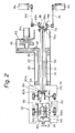
- Fig. 2 is a schematic view showing the constitution of a motion transmitting mechanism embodying the present invention, for transmitting motions to the wrist applied to the articulated industrial robot of Fig. 1;
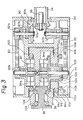
- Fig. 3 is a longitudinal sectional view showing an exemplary concrete constitution of a wrist mechanism according to the present invention; and
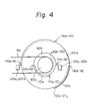
- Fig. 4 is a plan view as viewed in the direction of the arrows IV-IV in Fig. 3.
- Figure 1 is a perspective view showing an embodiment of an articulated industrial robot equipped with a wrist mechanism according to the present invention. Referring to Fig. 1, the industrial robot has a
robot body 10 mounted on aswivel base 12 so as to able to swivel in directions indicated by the arrow "I". Therobot body 10 is attached to theswivel base 12 by bolt means or the like. The base end of a robotupper arm 16 is joined to the upper end of therobot body 10 for pivotal motion about an axis C1, so that the robotupper arm 16 is swingable in directions indicated by the arrow "II". Arobot forearm 20 is joined, for tilting motion about an axis C2 in directions indicated by the arrow "III", to theupper end 18 of the robotupper arm 16. Therobot forearm 20 has amajor forearm section 22 extending forward from the axis C2 and a relatively shortrear extension 26 extending rearward from the axis C2.A wrist unit 30 is attached to the front end of themajor forearm section 22. Thewrist unit 30 comprises awrist base 32, anouter wrist 34 fixed to thewrist base 32, aninner wrist 36 supported on theouter wrist 34 and ahand holding part 38 attached to theinner wrist 36. Thewrist base 32 is rotatable together with theouter wrist 34 relative to themajor forearm section 22 in directions indicated by the arrow "IV". Theinner wrist 36 is rotatable relative to theouter wrist 34 in directions indicated by the arrow "V". Driving sources are provided to drive therobot body 10, the robotupper arm 16, therobot forearm 20 and thewrist unit 30, respectively, for various motions. A motor MS disposed contiguously to theswivel base 12 drives therobot base 10 in the direction of the arrow "I" through a motion transmitting mechanism arranged within theswivel base 12, a motor M1 drives the robotupper arm 16 in directions indicated by the arrow "II" for swing motion, and a motor, not shown, disposed behind the robotupper arm 16 in parallel to the motor M1 drives therobot forearm 20 for tilting motion in directions indicated by the arrow "III". These motors serving as driving sources and the corresponding driven parts are interlocked by mechanisms such as motion transmitting mechanisms and/or or reduction mechanism to appropriately control the motions of the driven parts. Indicated at 48 and 50 are elements constituting part of those mechanisms. - Three motors M2, M3 , and M4 for driving the
wrist base 32, theouter wrist 34, theinner wrist 36, respectively, and thehand holding part 38 of thewrist unit 30 attached to the front end of theforearm 20, are mounted collectively on therear extension 26 of theforearm 20. That is, the motors M2, M3 , and M4 are arranged so that the moment of mass of therear extension 26 including those three motors M2 , m3, and M4 about the axis C2 counterbalances the moment of mass of themajor forearm section 22 of theforearm 20 about the axis C2. A motion transmitting mechanism or a reduction gear mechanism for transmitting the rotation of the motors M3 and M4 is contained in ahousing 40, while a motion transmitting mechanism or a reduction gear mechanism for transmitting the rotation of the motor M2 is contained in acasing 42. The provision of those motors M2 , M3 , and M4 serving as the driving sources for the motions of three degrees of freedom of motion of thewrist unit 30 on therear extension 26 of theforearm 20 balances the motion of theforearm 20 about the axis C2. At the same time, the provision of the driving sources of thewrist unit 30 remote from thewrist unit 30 reduces the weight of thewrist unit 30 itself, which reduces the loads on the driving sources of thewrist unit 30, namely, the motors M2 , M3 , and M4. Although the embodiment of the present invention is shown in Fig. 1 as applied to an articulated industrial robot having therobot body 10 adapted to swivel on the swivel base, a wrist mechanism of the present invention which will be described hereinafter is applicable also to an articulated industrial robot having a robot body adapted to move laterally on a horizontal table. Futhermore, a wrist mechanism of the present invention is also applicable to an industrial robot having a wrist unit attached to the front end of a single linearly telescopic arm, for example, a cylindrical coordinate type robot. - Referring to Fig. 2, motion transmitting mechanisms incorporated into the
forearm 20 and thewrist unit 30 of the articulated industrial robot shown in Fig. 1 for giving at least two degrees of freedom of motion, three degrees of freedom of motion in this embodiment, to thewrist unit 30 will be described hereunder with reference to Fig. 2. - 'Referring to Fig. 2, the motors M 2 M3 , and M4 serving as the driving sources of the motions of the
wrist unit 30 of three degrees of freedom of motion are electric servomotors adapted to be controlled by command signals given by an external robot control unit. The rotative driving force of the motor M2 is reduced in the revolving rate by areduction gear 60, and then transmitted through agear mechanism 62 consisting of a pair of meshed gears and provided on the inner end of anouter shaft 52 to theouter shaft 52, and hence to thewrist base 32 fixed to the outer end of theouter shaft 52 and theouter wrist 34 to rotate theouter wrist 34 in the directions indicated by the arrow "V" in Fig. 1. Theouter shaft 52 is supported on themajor forearm section 22 inbearings 64. Owing to the inherent compact construction and the high reduction ratio, a publicly known harmonic drive reduction gear (Registered trademark) is advantageously applicable to the wrist mechanism as thereduction gear 60. The rotative driving force of the motor M3 is transmitted through a belt-and-pulley mechanism 74 and abevel gear mechanism 78 consisting of a pair ofbevel gears middle shaft 54 extended through and coaxially with theouter shaft 52 to themiddle shaft 54. Thebevel gear mechanism 78 is provided so as to be coaxial with a motion transmitting mechanism for transmitting the rotative force of the motor M4 , which will be described afterward, in order to contain three motion transmitting mechanisms compactly within theforearm 20 and thewrist unit 30 and to dispose the motors M3 and M4 on the opposite sides, respectively, of theforearm 20 so that a balanced construction is provided. The rotative force transmitted to themiddle shaft 54 is transmitted through abevel gear mechanism 80 consisting of a pair ofbevel gears middle shaft 54 and within theouter wrist 34 and through a belt-and-pulley mechanism 82 provided also within theouter wrist 34 to a reduction gear 84 (a harmonic drive reduction gear), and then to theinner wrist 36 to which theoutput wheel 84a of the reduction gear is fixed to drive theinner wrist 36 for tilting motion about an axis extending substantially perpendicular to the axis of rotation of themiddle shaft 54, as indicated by the arrow "V" in Fig. 1. Theinner wrist 36 is capable of being tilted relatively to theouter wrist 34 in the directions indicated by the arrow "V". Naturally, thehand holding part 38 provided within theinner wrist 36 moves together with theinner wrist 36 in the same directions. - The rotative driving force of the motor M4 is transmitted through a belt-and-
pulley mechanism 86 and then through abevel gear mechanism 88 consisting of a pair ofbevel gears inner shaft 56 extended through themiddle shaft 54 extending through theouter shaft 52 to theinner shaft 56. The rotative driving force transmitted to theinner shaft 56 is further transmitted through abevel gear mechanism 90 consisting of a pair ofbevel gears inner shaft 56 and within theouter wrist 34 opposite to thebevel gear mechanism 80 and a belt-and-pulley mechanism 92 to a harmonicdrive reduction gear 94 provided within theinner wrist 36, and then to thehand holding part 38 through abevel gear mechanism 96 consisting of abevel gear 96a fixed to theoutput wheel 94a of thereduction gear 94 and a bevel gear 94b. Thus thehand holding part 38 is driven for rotation about an axis which is substantially coaxial with the axis of rotation of theinner shaft 56, in the directions indicated by the arrow "VI" in Fig. 1. That is, thehand holding part 38 is capable of being rotated relative to theinner wrist 36 in the directions indicated by the arrow "VI" thereby rotating a robot hand attached to thehand holding part 38 in the same directions. As described hereinbefore, since the motors M2 , M3 , and M4 are electric servomotors, the rotary motions of three degrees of freedom of motion of thewrist unit 30 can be controlled to a desired extent according to the commands given by a robot control unit, respectively. - The above-mentioned motion transmitting mechanisms have significant advantages in that the
forearm 20 can be constructed in a slender form and that the mechanical rigidity of theforearm 20 can be improved due to the coaxial disposition of the high-speedrotary shafts rotary shaft 52 within theforearm 20, by the provision of the tworeduction gears wrist unit 30. The present invention may be embodied in a wrist mechanism, which will be described hereinafter, in which no reduction gear is provided in thewrist unit 30 and reduction gears are disposed contiguously to the motors M3 and M4 respectively, as in the case of the reduction gear associated with the motor M2. - Generally, in the above-mentioned
wrist unit 30, the angular extent of tilting motion of theinner wrist 36 is set to approximately 200° about the axis of the tilting motion, whereas the angular extent of the swivel motion of thehand holding part 38 is set to 360° (one full turn) or greater. For example, thehand holding part 38 is designed to cover an angular motion range of 180° in the clockwise direction, and also an angular motion range of 180° in the counterclockwise direction. That is, thehand holding part 38 is designed, to cover a total angular motion range of 360°, and thereby to carry out the desired robot actions. - Accordingly, in the above-mentioned exemplary mechanism of the present invention, the gear ratio between the
larger bevel gear 96a and thesmaller bevel gear 96b of thebevel gear mechanism 96 is determined selectively to have an appropriate reduction ratio such that at least the clockwise rotation and the counterclockwise rotation each through less than an angle of 180° of thelarger bevel gear 96a cause thehand holding part 38 to swivel through a desired angular range of swivel motion. Such a constitution enables the coaxial arrangement of both overtravel or near-zero detecting means for the tilting motion of theinner wrist 36 and overtravel or near-zero detecting means for the swivel motion of thehand holding part 38, on the axis of rotation of theinner wrist 36. - Figure 3 is a longitudinal sectional view showing an exemplary concrete constitution of a
wrist unit 30 provided with the above- mentioned overtravel detecting means and the near-zero detecting means. Figure 4 is a partial plan view along the line IV-IV of Fig. 3. In Figs. 3 and 4, the same reference numerals as those in Fig. 2 indicate concrete elements or parts corresponding to the elements or parts shown in Fig. 2. - Referring to Fig. 3, the
inner wrist 36 of thewrist unit 30 is supported on theouter wrist 34 inbearings bearings inner wrist 36 through the drivenpully 82b of the belt-and-pulley mechanism 82. The drivenpulley 82b is disposed coaxially with thebearings pulley 82b through themiddle shaft 54, thebevel gear mechanism 80 and the drivingpulley 82a of the belt-and-pulley mechanism 82. On the other hand, thehand holding part 38 is supported rotatably inbearings hand holding part 38, that is, the center axis of thebearings inner wrist 36. That is, thewrist unit 30 has, within theouter wrist 34, a constitution having two degrees of freedom of motion about three substantially perpendicular intersecting axes. Futhermore, the input rotative force is transmitted to thehand holding part 38 through the driven pulley of a belt-and-pulley mechanism 92 disposed coaxially with the drivenpulley 82b of the belt-and-pulley mechanism 82, while the direction of transmission of the input rotative force is changed by abevel gear mechanism 96. Accordingly, the overtravel detecting means and the near-zero detecting means for controlling the tilting motion of theinner wrist 36 include twodog disks ring 108 fixed to theinner wrist 36, and signal generators. For example, the overtravel of the tilting motion beyond the limit of motion can be detected by actuating a well-known signal generator, such as a limit switch or a photoelectric switch, provided at a preselected position of theouter wrist 34 with a protuberant dog formed at a limit position of the tilting motion in thedog disk 110a when the overtravel of the tilting motion occurs. The datum position and the direction of displacement from the original position (either in one direction or in the opposite direction indicated by the arrow "V" in Fig. 1) can be detected by the engagement between a protuberant dog formed in thedog disk 110b at a position corresponding to the datum position of motion of theinner wrist 36 and a signal generator fixedly provided for engagement with the dog of thedog disk 110b on theouter wrist 34. - The overtravel detecting means and the near-zero detecting means for the
hand holding part 38 includedog disks boss 114 of thebevel gear 96a coaxially with the twodog disks dog holding ring 108 at preselected positions thereon respectively, whereby the overtravel position and the datum position of motion of the swivel motion of thehand holding part 38 can be detected on the basis of the detection of the angle of rotation of thebevel gear 96a. That is, since thebevel gear 96a and thebevel gear 96b connected directly to thehand holding part 38 are meshed always and constitute a bevel gear mechanism of a fixed reduction ratio, the detection of the overtravel and the near-zero position of thehand holding part 38 can be attained through the detection of the angle of rotation of thebevel gear 96a (the larger bevel gear). Figure 4 shows a disposition of thedog disks limit switches inner wrist 36 are disposed side by side in an upper-and-lower relationship at coincident circular positions respectively. Thelimit switches hand holding part 38, are also disposed side by side in an upper-and-lower relationship at coincident circular positions respectively. Thedog disks limit switches dog positions 110a-OT1 and 110a-OT2 are positions where thedog disk 110a actuates the overtravel detectinglimit switch 120a for overtravel detection, a dog position llOb-NZ is a position where thedog disk 110b is engaged with the near-zero detectinglimit switch 120b for detecting the datum position of motion (near-zero position),dog positions 112a-OTl and 112a-OT2 are positions where thedog disk 112a actuates the overtravel detectinglimit switch 122a for overtravel detection, and adog position 112b-NZ is a position where thedog disk 112b is engaged with the near-zero detectinglimit switch 112b for the detection of the datum position of motion. - It is apparent from the above description that, according to the present invention, in a wrist unit of an industrial robot, the detection of-the overtravel of the motions of two degrees of freedom of motion about two substantially perpendicular intersecting axes of the wrist unit and the detection of the near-zero position of each working part can be attained by the corresponding overtravel detecting means and the near-zero detecting means which are arranged coaxially and compactly.
Claims (6)
1. A wrist mechanism of an industrial robot provided at the extremity of the robot arm and having at least two degrees of freedom of motion enabling a tilting motion and a swivel motion about two substantially perpendicular intersecting axes respectively, comprising: an outer wrist; an inner wrist disposed within and supported in the outer wrist for tilting motion about an axis; a hand holding part disposed within and supported in the inner wrist for rotation about an axis of rotation extending substantially perpendicular to the axis of tilting motion of said inner wrist; a motion transmitting mechanism for tilting motion for producing a tilting motion of said inner wrist from a first rotative input force introduced through said robot arm, another motion transmitting mechanism for swivel motion for producing a swivel motion of said hand holding part from a second rotative input force introduced through said robot arm; and overtravel detecting means arranged coaxially with said axis of tilting motion of said inner wrist for detecting the overtravel of the tilting motion of said inner wrist and the swivel motion of said hand holding part.
2. A wrist mechanism of an industrial robot according to Claim 1, wherein respective means for detecting datum positions of motion of the tilting motion of said inner wrist and the swivel motion of said hand holding motion are coaxially arranged about the axis of tilting motion of said inner wrist.
3. A wrist mechanism of an industrial robot according to Claim 2, wherein said motion transmitting mechanism for swivel motion includes a bevel gear mechanism.
4. A wrist mechanism of an industrial robot according to Claim 2, wherein the overtravel detecting means and the original position of motion detecting means each comprises a rotary disk type dog and switch means capable of being engaged with or disengaged from said rotary disk type dog.
5. A wrist mechanism of an industrial robot according to Claim 4, wherein said switch means comprises a limit switch.
6. A wrist mechanism of an industrial robot according to Claim 1, wherein said outer wrist is capable of being swiveled about an axis extending substantially coaxially with the axis of rotation of said hand holding part by a third rotative input force introduced thereto through said robot arm.
Applications Claiming Priority (2)
| Application Number | Priority Date | Filing Date | Title |
|---|---|---|---|
| JP57182930A JPS5973298A (en) | 1982-10-20 | 1982-10-20 | Wrist mechanism of industrial robot |
| JP182930/82 | 1982-10-20 |
Publications (2)
| Publication Number | Publication Date |
|---|---|
| EP0122942A1 true EP0122942A1 (en) | 1984-10-31 |
| EP0122942A4 EP0122942A4 (en) | 1986-04-15 |
Family
ID=16126856
Family Applications (1)
| Application Number | Title | Priority Date | Filing Date |
|---|---|---|---|
| EP19830903401 Withdrawn EP0122942A4 (en) | 1982-10-20 | 1983-10-20 | Wrist mechanism for industrial robot. |
Country Status (4)
| Country | Link |
|---|---|
| US (1) | US4586868A (en) |
| EP (1) | EP0122942A4 (en) |
| JP (1) | JPS5973298A (en) |
| WO (1) | WO1984001539A1 (en) |
Cited By (8)
| Publication number | Priority date | Publication date | Assignee | Title |
|---|---|---|---|---|
| GB2215243A (en) * | 1988-02-24 | 1989-09-20 | Jobs Spa | A chuck head for automatic machine tools |
| EP0378932A1 (en) * | 1989-01-20 | 1990-07-25 | KABUSHIKI KAISHA KOBE SEIKO SHO also known as Kobe Steel Ltd. | Wrist mechanism for industrial robot or the like |
| EP0479739A1 (en) * | 1990-10-04 | 1992-04-08 | COMAU S.p.A. | A robot wrist |
| EP1880809A1 (en) * | 2006-07-20 | 2008-01-23 | Fanuc Ltd | Arm structure of industrial robot |
| CN103381605A (en) * | 2012-05-04 | 2013-11-06 | 厄罗瓦公司 | Monitoring device for monitoring positions of a robot and manufacturing plant with a monitoring device |
| WO2017210499A1 (en) * | 2016-06-03 | 2017-12-07 | Covidien Lp | Control arm for robotic surgical systems |
| CN109195543A (en) * | 2016-06-03 | 2019-01-11 | 柯惠Lp公司 | Passive axle system for robotic surgical system |
| US11737843B2 (en) | 2016-06-03 | 2023-08-29 | Covidien Lp | Passive axis system for robotic surgical systems |
Families Citing this family (28)
| Publication number | Priority date | Publication date | Assignee | Title |
|---|---|---|---|---|
| JPS60127989A (en) * | 1983-12-14 | 1985-07-08 | ファナック株式会社 | Driving mechanism of wrist of industrial robot |
| DE3444478A1 (en) * | 1984-12-06 | 1986-06-12 | Hans Heynau GmbH, 8000 München | JOINT HEAD FOR INDUSTRIAL ROBOTS |
| US4780047A (en) * | 1985-04-05 | 1988-10-25 | Martin Marietta Energy Systems, Inc. | Advanced servo manipulator |
| DE3522337A1 (en) * | 1985-06-22 | 1987-02-05 | Bosch Gmbh Robert | ROBOT JOINT WITH AN ELECTRIC DRIVE MOTOR |
| JPS61293784A (en) * | 1985-06-24 | 1986-12-24 | ファナック株式会社 | Industrial robot |
| JPS62287991A (en) * | 1986-06-09 | 1987-12-14 | ファナック株式会社 | Wrist drive mechanism of industrial robot |
| DE3631024A1 (en) * | 1986-09-09 | 1988-03-17 | Mannesmann Ag | ROBOT ARM |
| JPS6374581A (en) * | 1986-09-17 | 1988-04-05 | トキコ株式会社 | Electric robot |
| JPS63185595A (en) * | 1987-01-28 | 1988-08-01 | フアナツク株式会社 | Wrist for industrial robot |
| JPS63272487A (en) * | 1987-04-28 | 1988-11-09 | 株式会社 オリイ | Multi-joint type robot |
| JPS6464791A (en) * | 1987-09-01 | 1989-03-10 | Mitsubishi Electric Corp | Joint device for industrial robot |
| US4795957A (en) * | 1987-09-03 | 1989-01-03 | Polaroid Corporation, Patent Department | Robot arm having motion-limiting tether |
| JP2591968B2 (en) * | 1987-12-28 | 1997-03-19 | 株式会社日立製作所 | Industrial robot wrist |
| US5046914A (en) * | 1988-07-12 | 1991-09-10 | Cybermation, Inc. | Parallel lifting device |
| JPH03128098A (en) * | 1989-10-13 | 1991-05-31 | Yamamoto Seisakusho:Kk | Prevention of generation of static electricity in dry cleaning machine and same machine therefor |
| JPH04100127A (en) * | 1990-08-17 | 1992-04-02 | Mitsubishi Electric Corp | Rotational angle controller |
| US5792135A (en) * | 1996-05-20 | 1998-08-11 | Intuitive Surgical, Inc. | Articulated surgical instrument for performing minimally invasive surgery with enhanced dexterity and sensitivity |
| WO2000075064A1 (en) * | 1999-06-04 | 2000-12-14 | Distributed Robotics Llc | Material handling device |
| SE516023C2 (en) | 1999-06-24 | 2001-11-12 | Abb Ab | Industrial robot comprising an gearbox configuration and method in an industrial robot |
| JP4605560B2 (en) * | 2005-12-05 | 2011-01-05 | 日本電産サンキョー株式会社 | Industrial robot |
| JP4846473B2 (en) * | 2006-07-12 | 2011-12-28 | 浩平 澤 | Drying device with recovery function and dry solvent recovery method |
| CN102259337B (en) * | 2010-05-28 | 2013-11-06 | 鸿富锦精密工业(深圳)有限公司 | Robot arm component |
| JP2012223849A (en) * | 2011-04-19 | 2012-11-15 | Yaskawa Electric Corp | Robot |
| EP2716419A4 (en) * | 2011-06-01 | 2015-04-08 | Yaskawa Denki Seisakusho Kk | Multijoint robot |
| JP5576911B2 (en) * | 2012-08-20 | 2014-08-20 | ファナック株式会社 | Articulated robot equipped with both-end arm members |
| CN103624796A (en) * | 2013-11-26 | 2014-03-12 | 苏州晓炎自动化设备有限公司 | Mechanism for rotating front end of robot wrist body |
| USD874655S1 (en) * | 2018-01-05 | 2020-02-04 | Medrobotics Corporation | Positioning arm for articulating robotic surgical system |
| CN108406777B (en) * | 2018-05-10 | 2023-06-20 | 华南理工大学 | Electronic component hand-eye coordination plug-in mechanism based on robot |
Citations (2)
| Publication number | Priority date | Publication date | Assignee | Title |
|---|---|---|---|---|
| DE2301423A1 (en) * | 1973-01-12 | 1974-07-25 | Fischer Brodbeck Gmbh | HANDLING DEVICE |
| EP0054763A1 (en) * | 1980-12-19 | 1982-06-30 | KUKA Schweissanlagen GmbH | Drive means for an articulated head affixed at the extremity of a manipulator arm |
Family Cites Families (7)
| Publication number | Priority date | Publication date | Assignee | Title |
|---|---|---|---|---|
| GB1481845A (en) * | 1973-07-16 | 1977-08-03 | Siemens Ag | Oscillator control circuits |
| JPS52155765A (en) * | 1976-06-18 | 1977-12-24 | Yachiyo Kougiyou Kenkiyuushiyo | Industrial robot |
| SU763082A1 (en) * | 1977-07-01 | 1980-09-15 | Предприятие П/Я Р-6930 | Modular manipulator |
| SU707793A1 (en) * | 1977-07-01 | 1980-01-05 | Предприятие П/Я Р-6930 | Manipulator gripper indexing device |
| JPS56142882U (en) * | 1980-03-28 | 1981-10-28 | ||
| JPS57205082A (en) * | 1981-06-12 | 1982-12-16 | Hitachi Ltd | Aligner for original point of robot |
| JPH0529266Y2 (en) * | 1988-03-30 | 1993-07-27 |
-
1982
- 1982-10-20 JP JP57182930A patent/JPS5973298A/en active Granted
-
1983
- 1983-10-20 US US06/624,508 patent/US4586868A/en not_active Expired - Fee Related
- 1983-10-20 EP EP19830903401 patent/EP0122942A4/en not_active Withdrawn
- 1983-10-20 WO PCT/JP1983/000368 patent/WO1984001539A1/en not_active Application Discontinuation
Patent Citations (2)
| Publication number | Priority date | Publication date | Assignee | Title |
|---|---|---|---|---|
| DE2301423A1 (en) * | 1973-01-12 | 1974-07-25 | Fischer Brodbeck Gmbh | HANDLING DEVICE |
| EP0054763A1 (en) * | 1980-12-19 | 1982-06-30 | KUKA Schweissanlagen GmbH | Drive means for an articulated head affixed at the extremity of a manipulator arm |
Non-Patent Citations (1)
| Title |
|---|
| See also references of WO8401539A1 * |
Cited By (19)
| Publication number | Priority date | Publication date | Assignee | Title |
|---|---|---|---|---|
| GB2215243A (en) * | 1988-02-24 | 1989-09-20 | Jobs Spa | A chuck head for automatic machine tools |
| US4904131A (en) * | 1988-02-24 | 1990-02-27 | Jobs S.P.A. | Chuck head for automatic machine tools |
| GB2215243B (en) * | 1988-02-24 | 1992-02-26 | Jobs Spa | A chuck head for automatic machine tools. |
| EP0378932A1 (en) * | 1989-01-20 | 1990-07-25 | KABUSHIKI KAISHA KOBE SEIKO SHO also known as Kobe Steel Ltd. | Wrist mechanism for industrial robot or the like |
| US5050450A (en) * | 1989-01-20 | 1991-09-24 | Kabushiki Kaisha Kobe Seiko Sho | Wrist mechanism for industrial robot or the like |
| EP0479739A1 (en) * | 1990-10-04 | 1992-04-08 | COMAU S.p.A. | A robot wrist |
| US5178032A (en) * | 1990-10-04 | 1993-01-12 | Comau Spa | Robot wrist |
| EP1880809A1 (en) * | 2006-07-20 | 2008-01-23 | Fanuc Ltd | Arm structure of industrial robot |
| CN103381605A (en) * | 2012-05-04 | 2013-11-06 | 厄罗瓦公司 | Monitoring device for monitoring positions of a robot and manufacturing plant with a monitoring device |
| CN103381605B (en) * | 2012-05-04 | 2016-07-13 | 厄罗瓦公司 | For robot device position monitoring monitoring device and containing its production system |
| WO2017210499A1 (en) * | 2016-06-03 | 2017-12-07 | Covidien Lp | Control arm for robotic surgical systems |
| CN107735040A (en) * | 2016-06-03 | 2018-02-23 | 柯惠Lp公司 | Control arm for robotic surgical system |
| CN109195543A (en) * | 2016-06-03 | 2019-01-11 | 柯惠Lp公司 | Passive axle system for robotic surgical system |
| CN107735040B (en) * | 2016-06-03 | 2021-06-18 | 柯惠Lp公司 | Control arm for robotic surgical system |
| CN113180835A (en) * | 2016-06-03 | 2021-07-30 | 柯惠Lp公司 | Control arm for robotic surgical system |
| CN114504387A (en) * | 2016-06-03 | 2022-05-17 | 柯惠Lp公司 | Passive shaft system for robotic surgical system |
| US11446099B2 (en) | 2016-06-03 | 2022-09-20 | Covidien Lp | Control arm for robotic surgical systems |
| US11464593B2 (en) | 2016-06-03 | 2022-10-11 | Covidien Lp | Passive axis system for robotic surgical systems |
| US11737843B2 (en) | 2016-06-03 | 2023-08-29 | Covidien Lp | Passive axis system for robotic surgical systems |
Also Published As
| Publication number | Publication date |
|---|---|
| EP0122942A4 (en) | 1986-04-15 |
| WO1984001539A1 (en) | 1984-04-26 |
| JPH028878B2 (en) | 1990-02-27 |
| JPS5973298A (en) | 1984-04-25 |
| US4586868A (en) | 1986-05-06 |
Similar Documents
| Publication | Publication Date | Title |
|---|---|---|
| US4586868A (en) | Wrist mechanism of an industrial robot | |
| US4626165A (en) | Industrial robot wrist mechanism | |
| EP0479739B1 (en) | A robot wrist | |
| JP4133188B2 (en) | Robot hand finger unit | |
| KR890000717B1 (en) | Industrial robot | |
| JP2004181610A (en) | Palm mechanism for robot hand | |
| JP2572483B2 (en) | Industrial robot equipment | |
| US4842474A (en) | Vertical multi-articulated robot | |
| US4717303A (en) | Joint mechanism for manipulators | |
| JPH0276689A (en) | Industrial robot | |
| EP0121576A1 (en) | Articulated arm type of industrial robot | |
| JPH07178684A (en) | Robot arm | |
| KR970001660B1 (en) | Vertical multi-link robot | |
| CN219854579U (en) | Six-axis mechanical arm device | |
| JPH0746475Y2 (en) | Rotation / swivel arm drive | |
| JPH0192087A (en) | Wrist mechanism for industrial robot | |
| JPH03104574A (en) | Articulated robot | |
| JPS63207576A (en) | Industrial robot | |
| JPH0411027Y2 (en) | ||
| KR20010095574A (en) | Vertical articulated robot | |
| JP2576282B2 (en) | Industrial robot | |
| JPS6317671Y2 (en) | ||
| JPH05253882A (en) | Robot having wrist of three degrees of freedom | |
| JP2021195824A (en) | Remote control device | |
| JPS6312949Y2 (en) |
Legal Events
| Date | Code | Title | Description |
|---|---|---|---|
| PUAI | Public reference made under article 153(3) epc to a published international application that has entered the european phase |
Free format text: ORIGINAL CODE: 0009012 |
|
| 17P | Request for examination filed |
Effective date: 19840613 |
|
| AK | Designated contracting states |
Designated state(s): DE FR GB |
|
| A4 | Supplementary search report drawn up and despatched |
Effective date: 19860415 |
|
| STAA | Information on the status of an ep patent application or granted ep patent |
Free format text: STATUS: THE APPLICATION IS DEEMED TO BE WITHDRAWN |
|
| 18D | Application deemed to be withdrawn |
Effective date: 19880503 |
|
| RIN1 | Information on inventor provided before grant (corrected) |
Inventor name: ITO, SUSUMU Inventor name: INAGAKI, SHIGEMI Inventor name: NAKASHIMA, SEIICHIRO |