EP0122639B1 - Flacher Drahtkorb, z.B. als Schublade verwendbar - Google Patents
Flacher Drahtkorb, z.B. als Schublade verwendbar Download PDFInfo
- Publication number
- EP0122639B1 EP0122639B1 EP84104410A EP84104410A EP0122639B1 EP 0122639 B1 EP0122639 B1 EP 0122639B1 EP 84104410 A EP84104410 A EP 84104410A EP 84104410 A EP84104410 A EP 84104410A EP 0122639 B1 EP0122639 B1 EP 0122639B1
- Authority
- EP
- European Patent Office
- Prior art keywords
- wire
- tray
- side walls
- limbs
- walls
- Prior art date
- Legal status (The legal status is an assumption and is not a legal conclusion. Google has not performed a legal analysis and makes no representation as to the accuracy of the status listed.)
- Expired
Links
Images

Classifications
-
- B—PERFORMING OPERATIONS; TRANSPORTING
- B65—CONVEYING; PACKING; STORING; HANDLING THIN OR FILAMENTARY MATERIAL
- B65D—CONTAINERS FOR STORAGE OR TRANSPORT OF ARTICLES OR MATERIALS, e.g. BAGS, BARRELS, BOTTLES, BOXES, CANS, CARTONS, CRATES, DRUMS, JARS, TANKS, HOPPERS, FORWARDING CONTAINERS; ACCESSORIES, CLOSURES, OR FITTINGS THEREFOR; PACKAGING ELEMENTS; PACKAGES
- B65D7/00—Containers having bodies formed by interconnecting or uniting two or more rigid, or substantially rigid, components made wholly or mainly of metal
- B65D7/12—Containers having bodies formed by interconnecting or uniting two or more rigid, or substantially rigid, components made wholly or mainly of metal characterised by wall construction or by connections between walls
- B65D7/14—Containers having bodies formed by interconnecting or uniting two or more rigid, or substantially rigid, components made wholly or mainly of metal characterised by wall construction or by connections between walls of skeleton or like apertured construction, e.g. baskets or carriers formed of wire mesh, of interconnected bands, bars, or rods, or of perforated sheet metal
- B65D7/20—Containers having bodies formed by interconnecting or uniting two or more rigid, or substantially rigid, components made wholly or mainly of metal characterised by wall construction or by connections between walls of skeleton or like apertured construction, e.g. baskets or carriers formed of wire mesh, of interconnected bands, bars, or rods, or of perforated sheet metal made of wire
-
- A—HUMAN NECESSITIES
- A47—FURNITURE; DOMESTIC ARTICLES OR APPLIANCES; COFFEE MILLS; SPICE MILLS; SUCTION CLEANERS IN GENERAL
- A47B—TABLES; DESKS; OFFICE FURNITURE; CABINETS; DRAWERS; GENERAL DETAILS OF FURNITURE
- A47B88/00—Drawers for tables, cabinets or like furniture; Guides for drawers
- A47B88/90—Constructional details of drawers
-
- B—PERFORMING OPERATIONS; TRANSPORTING
- B65—CONVEYING; PACKING; STORING; HANDLING THIN OR FILAMENTARY MATERIAL
- B65D—CONTAINERS FOR STORAGE OR TRANSPORT OF ARTICLES OR MATERIALS, e.g. BAGS, BARRELS, BOTTLES, BOXES, CANS, CARTONS, CRATES, DRUMS, JARS, TANKS, HOPPERS, FORWARDING CONTAINERS; ACCESSORIES, CLOSURES, OR FITTINGS THEREFOR; PACKAGING ELEMENTS; PACKAGES
- B65D21/00—Nestable, stackable or joinable containers; Containers of variable capacity
- B65D21/02—Containers specially shaped, or provided with fittings or attachments, to facilitate nesting, stacking, or joining together
- B65D21/0233—Nestable containers
-
- A—HUMAN NECESSITIES
- A47—FURNITURE; DOMESTIC ARTICLES OR APPLIANCES; COFFEE MILLS; SPICE MILLS; SUCTION CLEANERS IN GENERAL
- A47B—TABLES; DESKS; OFFICE FURNITURE; CABINETS; DRAWERS; GENERAL DETAILS OF FURNITURE
- A47B88/00—Drawers for tables, cabinets or like furniture; Guides for drawers
- A47B88/40—Sliding drawers; Slides or guides therefor
- A47B2088/401—Slides or guides for wire baskets
-
- A—HUMAN NECESSITIES
- A47—FURNITURE; DOMESTIC ARTICLES OR APPLIANCES; COFFEE MILLS; SPICE MILLS; SUCTION CLEANERS IN GENERAL
- A47B—TABLES; DESKS; OFFICE FURNITURE; CABINETS; DRAWERS; GENERAL DETAILS OF FURNITURE
- A47B2210/00—General construction of drawers, guides and guide devices
- A47B2210/0002—Guide construction for drawers
- A47B2210/0024—Slides, guides for wire basket or drawer
-
- A—HUMAN NECESSITIES
- A47—FURNITURE; DOMESTIC ARTICLES OR APPLIANCES; COFFEE MILLS; SPICE MILLS; SUCTION CLEANERS IN GENERAL
- A47B—TABLES; DESKS; OFFICE FURNITURE; CABINETS; DRAWERS; GENERAL DETAILS OF FURNITURE
- A47B2210/00—General construction of drawers, guides and guide devices
- A47B2210/04—Metal wire drawers
-
- A—HUMAN NECESSITIES
- A47—FURNITURE; DOMESTIC ARTICLES OR APPLIANCES; COFFEE MILLS; SPICE MILLS; SUCTION CLEANERS IN GENERAL
- A47B—TABLES; DESKS; OFFICE FURNITURE; CABINETS; DRAWERS; GENERAL DETAILS OF FURNITURE
- A47B88/00—Drawers for tables, cabinets or like furniture; Guides for drawers
- A47B88/90—Constructional details of drawers
- A47B88/919—Accessories or additional elements for drawers, e.g. drawer lighting
- A47B88/931—Rails or rods mounted above the drawer walls, e.g. for stabilisation of the drawer or for suspension of the content
Definitions
- the invention relates to a tray, preferably of metal wire, and for instance applicable as a drawer, said tray comprising a rectangular, optionally quadrangular bottom and circumferential side walls, the bottom and side walls being constituted by a wire frame, in which a plurality of substantially U-shaped wire lengths are secured on the inside thereof.
- the object of the present invention is to provide a tray of the above type which permits piling of several identical trays according to the "drinking glass principle" although the sidewalls of the tray are vertical.
- Such a tray can be characterised in that the bottom and the side walls are integrally formed since they are constituted by a wire frame, in which a plurality of substantially U-shaped wire lengths are secured on the inside thereof, the free wire webs of the U forming two opposing vertical side walls of the tray, whereas the bottom wire web of the U forms the bottom of the tray, and that the free wire webs of each side wall are located in pairs, whereby the wire webs (side limbs) of each pair converge downwards, and in that a slide bar set comprising preferably a fastened bar and a slidable bar is mounted on the outside of two opposing side walls at the lower rim of said walls, the fastened bar comprising parts, which snap a bottom wire web of an outlying U-shaped wire length in the bottom of the tray when said bar is pressed from the outside against the side wall in question.
- a tray is easily pilable on another tray according to the "drinking glass principle" since the pair of free wire webs of the first tray is located inside the wire frame of the second (lower) tray and from above can be made abutting the pair of free wire webs of the second tray.
- the side walls are vertical, the volume of the tray can be utilized to an optimum extent, and when the tray serves as a drawer in a cupboard, for instance in a kitchen, the volume of the cupboard can be utilized to an optimum extent too.
- the bottom web of the U of an additional U-shaped wire length at each end of the side walls is located in such a manner that seen in radial direction relative to the centre of the tray it is located a short distance inside a transverse side wall next to the two opposing side walls, and in that the free webs (side limbs) of said additional U-shaped wire length are part of two adjacent side walls and are located adjacent the ends of said walls converge downwardly.
- auxiliary parts if any, are easy to mount on the outside of the tray, said parts overlapping and snapping around the said bottom web.
- the free wire webs of a side wall may alternately form an angle of 90°+v/2 and 90°-v/2 with the portion of the wire frame present in the side wall in question, the angle of convergence v of two succeeding free wire webs ranging from 5 to 40°, and preferably being 30°. In this manner a very reliable piling of the trays is permitted on top of and within each other.
- the metal wire used can be coated with plastics, whereby the metal wire is suitably protected against oxidation.
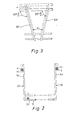
- the tray illustrated in Figure 1 is preferably made of metal wire and may for instance be used as a drawer. It comprises a rectangular bottom 1 and circumferential side walls 2a, 2b, 2c, 2d. As illustrated, the bottom and the side walls are integrally formed. They consist of a wire frame 4 and a plurality of substantially U-shaped wire lengths 5, cf. Figure 2, secured to the inside of said frame 4. For the sake of clarity, only a few wire lengths have been provided with the reference numeral 5. In Figure 2 only one wire length is illustrated, but in Figure 1 it is shown that the tray may comprise for instance 2x14 U-shaped wire lengths. The free wire webs of the U form two opposing vertical side walls, cf. the side walls 2b and 2d of Figure 1.
- the bottom wire web 5c of Figure 2 forms the bottom 1 of the tray.
- the "free" wire webs 5a of each side walls 2b are located in pairs, the wire webs of each pair converging downwards, which has been particularly illustrated in Figure 3.
- the wire webs of a pair have been indicated by 5a' and 5a".
- the free wire webs 5a, 5b are secured to the wire frame 4 at the side 14 radially facing inwards of the latter.
- the U-shaped wire length 15 is, however, single and its free webs 15a and 15b in a pair of opposing side walls 2a and 2d are located adjacent one end of said walls (in Figure 1 said end is the left end of the walls 2b and 2d).
- the bottom web of this wire length is situated in such a manner that seen in radial direction relative to the centre of the tray it is located a short distance inside the transverse side wall 2a adjacent the two opposing side walls. The distance that the bottom web is located inside said wall is indicated by m in Figure 1.
- a slide bar set 16 is mounted at the lower rim of two opposing side walls 2a and 2c on the outside thereof.
- Each set comprises a bar 16a fastened on the tray as well as a bar 16b slidable relative to the bar 16a.
- the bar 16a comprises parts 17, which overlap and snap the bottom wire web 15c of an outlying U-shaped wire length 15 in the bottom 1 of the drawer when the bar 16a has been pressed against the side wall 2a from the outside.
- the free wire webs 5a', 5a" in a side wall are located in such a manner that alternatively they form an angle of 90°+v/2 and 90°-v/2 with the portion of the wire frame 4 present in the side wall in question.
- the angle of convergence v of two succeeding free wire webs 5a' and 5a" is approximately 30° in Figure 3.
- v is in the range of 5 to 40°.
- the metal wire used in the tray according to the invention may be coated with plastics, whereby the tray is more chemical-resistant.
- the invention may be varied in many ways without thereby deviating from the scope of the invention. Thus cast plastics may be used instead of metal wire.
Landscapes
- Engineering & Computer Science (AREA)
- Mechanical Engineering (AREA)
- Table Equipment (AREA)
- Food-Manufacturing Devices (AREA)
- Electrostatic Charge, Transfer And Separation In Electrography (AREA)
- Packging For Living Organisms, Food Or Medicinal Products That Are Sensitive To Environmental Conditiond (AREA)
- Sheet Holders (AREA)
- Cash Registers Or Receiving Machines (AREA)
- Pit Excavations, Shoring, Fill Or Stabilisation Of Slopes (AREA)
- Details Of Rigid Or Semi-Rigid Containers (AREA)
- Drawers Of Furniture (AREA)
- Rigid Containers With Two Or More Constituent Elements (AREA)
- Stackable Containers (AREA)
- Washing And Drying Of Tableware (AREA)
Claims (4)
Priority Applications (1)
| Application Number | Priority Date | Filing Date | Title |
|---|---|---|---|
| AT84104410T ATE36228T1 (de) | 1983-04-19 | 1984-04-18 | Flacher drahtkorb, z.b. als schublade verwendbar. |
Applications Claiming Priority (2)
| Application Number | Priority Date | Filing Date | Title |
|---|---|---|---|
| DK171983A DK156114C (da) | 1983-04-19 | 1983-04-19 | Bakke udformet af traadstykker, og som f.eks. kan bruges som skuffe. |
| DK1719/83 | 1983-04-19 |
Publications (3)
| Publication Number | Publication Date |
|---|---|
| EP0122639A2 EP0122639A2 (de) | 1984-10-24 |
| EP0122639A3 EP0122639A3 (en) | 1985-09-11 |
| EP0122639B1 true EP0122639B1 (de) | 1988-08-10 |
Family
ID=8107500
Family Applications (1)
| Application Number | Title | Priority Date | Filing Date |
|---|---|---|---|
| EP84104410A Expired EP0122639B1 (de) | 1983-04-19 | 1984-04-18 | Flacher Drahtkorb, z.B. als Schublade verwendbar |
Country Status (4)
| Country | Link |
|---|---|
| EP (1) | EP0122639B1 (de) |
| AT (1) | ATE36228T1 (de) |
| DE (1) | DE3473220D1 (de) |
| DK (1) | DK156114C (de) |
Families Citing this family (1)
| Publication number | Priority date | Publication date | Assignee | Title |
|---|---|---|---|---|
| SE501294C2 (sv) * | 1994-01-13 | 1995-01-09 | Pelly Ind Ab | Anordning vid trådback, samt sätt för dess framställning |
Family Cites Families (5)
| Publication number | Priority date | Publication date | Assignee | Title |
|---|---|---|---|---|
| US2266857A (en) * | 1939-07-19 | 1941-12-23 | Forrest S Field | Refrigerator |
| US2698249A (en) * | 1949-09-13 | 1954-12-28 | Kraft Foods Co | Cheese packaging |
| BE623159A (de) * | 1961-10-07 | |||
| DE1960390A1 (de) * | 1969-12-02 | 1971-06-09 | Bosch Hausgeraete Gmbh | Korb,insbesondere Einsatzkorb fuer Gefriertruhen |
| US3752352A (en) * | 1971-07-08 | 1973-08-14 | Y Senecal | Stackable nestable container |
-
1983
- 1983-04-19 DK DK171983A patent/DK156114C/da not_active IP Right Cessation
-
1984
- 1984-04-18 AT AT84104410T patent/ATE36228T1/de not_active IP Right Cessation
- 1984-04-18 DE DE8484104410T patent/DE3473220D1/de not_active Expired
- 1984-04-18 EP EP84104410A patent/EP0122639B1/de not_active Expired
Also Published As
| Publication number | Publication date |
|---|---|
| DK171983D0 (da) | 1983-04-19 |
| DK171983A (da) | 1984-10-20 |
| ATE36228T1 (de) | 1988-08-15 |
| DK156114B (da) | 1989-06-26 |
| EP0122639A2 (de) | 1984-10-24 |
| DK156114C (da) | 1989-11-20 |
| DE3473220D1 (en) | 1988-09-15 |
| EP0122639A3 (en) | 1985-09-11 |
Similar Documents
| Publication | Publication Date | Title |
|---|---|---|
| US4426001A (en) | Nestable and stackable container | |
| US3447715A (en) | Containers | |
| US5927658A (en) | Wire trellis tray for cables and electrical conductors | |
| EP0024861A1 (de) | Stapelbare Behälter für Pflanzen oder dgl. | |
| CA1040599A (en) | Partition assembly and partition strips therefor | |
| WO2001017082A8 (en) | Cable tray | |
| US4265184A (en) | Metal cornerboard for pallets | |
| US4837994A (en) | Composite metal/concrete floor and method | |
| NZ225385A (en) | Stackable container: lugs in lid fit in slots in double walled sides | |
| USRE24984E (en) | Nesting and stacking trays | |
| GB2201663A (en) | Stackable boxes for carrying fruit | |
| EP0122639A2 (de) | Flacher Drahtkorb, z.B. als Schublade verwendbar | |
| US3951105A (en) | Animal cage lid | |
| US4326629A (en) | Bottle carrier | |
| NO932153D0 (no) | Oppbrettet bunnform for ost, og plateemne for samme | |
| US4643325A (en) | Bail mounting structure | |
| US2903150A (en) | Bottle crate | |
| GB1061780A (en) | Shift type nesting and stacking receptacle | |
| GB2056951A (en) | Stacking trays | |
| EP0836578B1 (de) | Förderband | |
| US2160631A (en) | Crate | |
| EP1102377B1 (de) | Übergangsstückabdeckung für Kabelleitung | |
| US2850199A (en) | Milk crate | |
| EP0235143B1 (de) | Klemme zum festhalten zweier aufeinander gesetzter teile oder zweier auf einander selbstgefalteter teile einer schachtel oder dergleichen, hergestellt aus einem formblatt | |
| EP0558909B1 (de) | Stapelbarer Ablagekasten für Papier u.ä. |
Legal Events
| Date | Code | Title | Description |
|---|---|---|---|
| PUAI | Public reference made under article 153(3) epc to a published international application that has entered the european phase |
Free format text: ORIGINAL CODE: 0009012 |
|
| AK | Designated contracting states |
Designated state(s): AT CH DE FR IT LI SE |
|
| PUAL | Search report despatched |
Free format text: ORIGINAL CODE: 0009013 |
|
| AK | Designated contracting states |
Designated state(s): AT CH DE FR IT LI SE |
|
| 17P | Request for examination filed |
Effective date: 19860310 |
|
| 17Q | First examination report despatched |
Effective date: 19870317 |
|
| RAP1 | Party data changed (applicant data changed or rights of an application transferred) |
Owner name: INTER-IKEA A/S |
|
| GRAA | (expected) grant |
Free format text: ORIGINAL CODE: 0009210 |
|
| AK | Designated contracting states |
Kind code of ref document: B1 Designated state(s): AT CH DE FR IT LI SE |
|
| REF | Corresponds to: |
Ref document number: 36228 Country of ref document: AT Date of ref document: 19880815 Kind code of ref document: T |
|
| REF | Corresponds to: |
Ref document number: 3473220 Country of ref document: DE Date of ref document: 19880915 |
|
| ET | Fr: translation filed | ||
| ITF | It: translation for a ep patent filed | ||
| PLBE | No opposition filed within time limit |
Free format text: ORIGINAL CODE: 0009261 |
|
| STAA | Information on the status of an ep patent application or granted ep patent |
Free format text: STATUS: NO OPPOSITION FILED WITHIN TIME LIMIT |
|
| 26N | No opposition filed | ||
| ITTA | It: last paid annual fee | ||
| PGFP | Annual fee paid to national office [announced via postgrant information from national office to epo] |
Ref country code: SE Payment date: 19920429 Year of fee payment: 9 |
|
| PGFP | Annual fee paid to national office [announced via postgrant information from national office to epo] |
Ref country code: FR Payment date: 19920430 Year of fee payment: 9 Ref country code: CH Payment date: 19920430 Year of fee payment: 9 Ref country code: AT Payment date: 19920430 Year of fee payment: 9 |
|
| PGFP | Annual fee paid to national office [announced via postgrant information from national office to epo] |
Ref country code: DE Payment date: 19920529 Year of fee payment: 9 |
|
| PG25 | Lapsed in a contracting state [announced via postgrant information from national office to epo] |
Ref country code: AT Effective date: 19930418 |
|
| PG25 | Lapsed in a contracting state [announced via postgrant information from national office to epo] |
Ref country code: SE Effective date: 19930419 |
|
| PG25 | Lapsed in a contracting state [announced via postgrant information from national office to epo] |
Ref country code: LI Effective date: 19930430 Ref country code: CH Effective date: 19930430 |
|
| PG25 | Lapsed in a contracting state [announced via postgrant information from national office to epo] |
Ref country code: FR Effective date: 19931229 |
|
| REG | Reference to a national code |
Ref country code: CH Ref legal event code: PL |
|
| PG25 | Lapsed in a contracting state [announced via postgrant information from national office to epo] |
Ref country code: DE Effective date: 19940101 |
|
| REG | Reference to a national code |
Ref country code: FR Ref legal event code: ST |
|
| EUG | Se: european patent has lapsed |
Ref document number: 84104410.0 Effective date: 19931110 |