US4426001A - Nestable and stackable container - Google Patents
Nestable and stackable container Download PDFInfo
- Publication number
- US4426001A US4426001A US06/302,075 US30207581A US4426001A US 4426001 A US4426001 A US 4426001A US 30207581 A US30207581 A US 30207581A US 4426001 A US4426001 A US 4426001A
- Authority
- US
- United States
- Prior art keywords
- container
- saddles
- feet
- walls
- clearances
- Prior art date
- Legal status (The legal status is an assumption and is not a legal conclusion. Google has not performed a legal analysis and makes no representation as to the accuracy of the status listed.)
- Expired - Fee Related
Links
Images


Classifications
-
- B—PERFORMING OPERATIONS; TRANSPORTING
- B65—CONVEYING; PACKING; STORING; HANDLING THIN OR FILAMENTARY MATERIAL
- B65D—CONTAINERS FOR STORAGE OR TRANSPORT OF ARTICLES OR MATERIALS, e.g. BAGS, BARRELS, BOTTLES, BOXES, CANS, CARTONS, CRATES, DRUMS, JARS, TANKS, HOPPERS, FORWARDING CONTAINERS; ACCESSORIES, CLOSURES, OR FITTINGS THEREFOR; PACKAGING ELEMENTS; PACKAGES
- B65D21/00—Nestable, stackable or joinable containers; Containers of variable capacity
- B65D21/02—Containers specially shaped, or provided with fittings or attachments, to facilitate nesting, stacking, or joining together
- B65D21/04—Open-ended containers shaped to be nested when empty and to be superposed when full
- B65D21/043—Identical stackable containers specially adapted for nesting after rotation around a vertical axis
- B65D21/046—Identical stackable containers specially adapted for nesting after rotation around a vertical axis about 90°
Definitions
- This invention relates generally to containers and refers more particularly to a container which will either stack or nest with a second container of identical construction.
- the container of this invention has a square bottom and side and end walls projecting upwardly from the bottom.
- Each of the walls has a lower section and an upper section spaced outwardly from the lower section sufficiently to permit the container to nest with a second container of identical construction.
- each wall of the container has a plurality of feet spaced from one another along the outer side of the lower section thereof.
- Each wall also has a plurality of saddles spaced from one another along the inner side of the upper section thereof. The saddles are located directly above the feet so that the feet will engage the saddles of a similarly oriented lower container of identical construction and support the same in a stacked relationship.
- Each wall of the container has clearances laterally offset from the saddles along the inner side of the upper section.
- the clearances are arranged so that when a container is turned 90° with respect to a lower container of identical construction, it may be lowered into a nested relationship therewith without interference because the feet will enter and pass through the clearance of the lower container.
- the container may be slid across the top of a lower container of identical construction to a stacked position, or even to a nested position, although the slide-on feature is used primarily for stacking. Certain of the feet and saddles are utilized for sliding on.
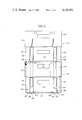
- FIG. 1 is a side elevational view with parts in section showing two identical containers of this invention stacked one upon the other.
- FIG. 2 is a side elevational view of the container.
- FIG. 3 is an end elevational view of the container.
- FIG. 4 is a top plan view.
- FIG. 5 is a view partially in elevation and partly in section taken on the line 5--5 in FIG. 4, showing two nested containers.
- FIG. 6 is a sectional view taken on the line 6--6 in FIG. 4.
- FIG. 7 is a sectional view taken on the line 7--7 in FIG. 4.
- FIG. 8 is a sectional view taken on the line 8--8 in FIG. 5.
- FIG. 9 is a view showing the container of this invention being slid laterally towards a position in which it may be lowered to a nested relationship with respect to a 90° turned lower container of identical construction.
- FIG. 10 is a view showing the container being slid laterally towards a stacked position with respect to a similarly oriented lower container of identical construction.
- FIG. 11 is similar to FIG. 10 but shows the relationship of the two containers as viewed from a different side.
- the container there shown is preferably of one-piece molded construction formed of a suitable plastic material such as polyethylene or polypropylene.
- the container is generally designated by the reference numeral 10 and is shown in some of the views with a second container of identical construction.
- the container 10 has a horizontal rectangular bottom wall 12, side walls 14 and 16 and end walls 18 and 20.
- the bottom 12 may be of any suitable construction. Its main surface area is shown as having a grid-like configuration which is desirable from the standpoint of weight reduction and ease with which it may be cleaned.
- the walls 14 and 16 are referred to as “side walls” and the walls 18 and 20 are referred to as “end walls” merely for the sake of convenience since they are of somewhat different construction as will be apparent from the description to follow. However, the side and end walls are of the same width because the bottom is square.
- the side walls 14 and 16 are identical to one another.
- the end walls 18 and 20 are identical to one another although of somewhat different construction from the side walls.
- Each side wall extends vertically upwardly from the side edges of the bottom 12 and has a lower vertical section 24 and an upper vertical section 26 spaced laterally outwardly from the lower section and joined thereto by a generally horizontal ledge 28.
- Each end wall extends vertically upwardly from the end edges of the bottom 12 and has a lower vertical section 30 and an upper vertical section 32 spaced laterally outwardly from the lower section and joined thereto by a generally horizontal ledge 34.
- the ledges 28 and 34 lie in a common horizontal plane and connect end to end at the corners of the container.
- the upper sections of the side and end walls are spaced outwardly from the lower sections thereof a distance sufficient to permit nesting and also to clear the stacking strips which are more fully described hereinafter.
- each of the side walls 14 and 16 has a pair of laterally spaced, elongated, vertical, rectangular lower stacking strips 36 and 38 on the outer side of the lower section 24 thereof.
- Strips 36 and 38 are identical. They extend from the ledge 28 down to a point slightly above the bottom of the container, terminating at the lower ends in flanges 40 and 42 which have aligned horizontal recesses in their lower edges as shown. Between the flanges and the side wall proper, the strips are recessed where indicated at 44 and 46. The recesses 44 and 46 are horizontal and closed at the ends by right angle extensions 47 and 49 of the flanges 40 and 42 which turn inwardly and merge into the side wall proper.
- the recessses in particular the horizontal top surfaces thereof, are supporting feet for the container. These feet are horizontally aligned.
- the strips are symmetrically arranged on each side wall by being spaced equal distances from the vertical center line of the side wall on opposite sides thereof and are preferably formed integrally with the side wall.
- Each of the side walls 14 and 16 has a pair of laterally spaced, elongated, vertical, rectangular upper stacking strips 48 and 50 on the inner side of the upper section 26 thereof.
- the strips 48 and 50 are identical. They extend from the ledge 28 up to a point slightly below the upper edge of the container, terminating at the upper ends in aligned horizontal saddles or flanges 52 and 54. Between the saddles 52 and 54 and the side wall proper, the strips have open-ended recesses 56 and 58.
- the upper strips 48 and 50 are located directly above the lower strips 36 and 38 and accordingly the saddles 52 and 54 are respectively located directly above the feet 44 and 46.
- the upper strips 48 and 50 are slightly narrower than the lower strips 36 and 38 and the recesses or feet 44, 46 are sufficiently wider than the saddles 52, 54 that the saddles of a lower container will be received in the recesses or feet 44, 46 of a similarly oriented upper container of identical construction for stacking with the flanges 40 and 42 of strips 36 and 38 extending into recesses 56 and 58 of the strips 48 and 50 and the flange extensions 47 and 49 confining the ends of saddles 52 and 54 and preventing lateral movement between the feet and saddles.
- Strips 48 and 50 are preferably formed integrally with the side wall.
- Each of the side walls 14 and 16 has a relatively wide central strip 60 on the inner side of the upper section 26 thereof.
- the central strip 60 extends from the ledge 28 up to approximately the level of the top edge of the side wall, terminating at its upper end in a flange 62.
- Flange 62 is aligned with saddles 52 and 54 when viewed from the top (FIG. 4) although not at the same height as seen in FIGS. 2 and 7.
- the laterally outer horizontal top edge portions 64 of the flange 62 are disposed at the level of the top edge of the side wall, while the horizontal central portion 66 thereof is disposed at a slightly lower level beneath saddles 52 and 54 and is joined to the laterally outer portions by inclined portions 68 and 69.
- the central strip between the flange 62 and the side wall proper is recessed along a horizontal line where indicated at 70 at approximately the same level as the horizontal recesses 56 and 58.
- the central strip is rectangular except for the portions 66, 68 and 69 of the top edge thereof, and is preferably formed integrally with the side wall.
- the central strip together with the saddles cooperate with the feet to serve as a means to permit lateral slide-on of an upper container relative to a lower container particularly for stacking but also for nesting, as will become more apparent hereinafter.
- each of the end walls 18 and 20 has two pairs of laterally spaced elongated, vertical rectangular lower stacking strips 80, 81, 82 and 83 on the outer side of the lower section 30 thereof. These strips, which are preferably integral with the container end walls, extend from the ledge 34 down to a point slightly above the bottom of the container.
- the strips 80 and 81 are disposed on one side of the vertical center line of each end wall and the strips 82 and 83 are disposed on the opposite side of the vertical center line, with the innermost strips 81 and 82 spaced from the center line an equal distance and with the outermost strips 80 and 83 spaced from the innermost strips an equal distance so that the arrangement of strips 80-83 on each side wall is symmetrical with respect to the vertical centerline.
- the innermost strips 81 and 82 are mirror images of one another and terminate at their lower ends in flanges 84 and 86. Between the flanges and the end wall proper, the strips 81 and 82 are recessed where indicated at 88 and 90.
- the recesses 88 and 90 are aligned horizontally, and are open at their laterally inner ends but closed at their laterally outer ends by right angle extensions 92 and 94 of flanges 84 and 86 which turn inwardly and merge into the end wall proper.
- the recesses, in particular the aligned horizontal top surfaces thereof, are supporting feet for the container.
- the lower edges of the flanges 84 and 86 have the recessed configuration shown in FIG. 3, being sloped upwardly from the inner extremities, and then extending horizontally to the right angle extensions 92 and 94 of the flanges.
- the outermost strips 80 and 83 are mirror images of one another and terminate at their lower ends in flanges 96 and 98. Between the flanges and the end wall proper, the strips 80 and 83 are recessed as indicated at 100 and 102.
- the recesses are aligned horizontally and are open at their laterally outer ends but closed at their laterally inner ends by right angle extensions 104 and 106 which turn inwardly and merge into the end wall proper.
- the recesses 100 and 102, in particular the aligned horizontal top surfaces thereof, are supporting feet for the container and are at a lower level than feet 88 and 90 of strips 81 and 82 although aligned therewith when viewed from above.
- Each of the end walls 18 and 20 has a pair of laterally spaced elongated, vertical, rectangular upper stacking strips 108 and 110 on the inner side of the upper section 32 thereof. These strips are identical and extend from the ledge 34 up to a point slightly below the upper edge of the container, terminating at their upper ends in horizontally aligned saddles or flanges 112 and 114. Between the saddles 112 and 114 and the end wall proper, the strips have recesses 116 and 118 which are closed at the outer ends and open at the inner ends.
- the upper strips 108 and 110 are located directly above the lower strips 80 and 83 and accordingly the saddles 112 and 114 are respectively located directly above the feet 100 and 102.
- Each of the end walls 18 and 20 has a relatively wide central strip 120 on the inner side of the upper section 32 thereof.
- the central strip 120 extends from the ledge 34 up to approximately the level of the top edge of the end wall, terminating at its upper edge in a flange 122 which is aligned with saddles 112 and 114 when viewed from above (FIG. 4) although not at the same height as seen in FIGS. 3 and 6.
- the laterally outer horizontal top edge portions 124 of the flange 122 are disposed at the level of the top edge of the end wall, while the horizontal central portion 126 thereof is disposed at a slightly lower level beneath saddles 112 and 114 and is joined to the outer portions by inclined portions 128 and 130.
- the central strip between the flange 122 and the end wall proper is recessed along a horizontal line indicated at 132 at approximately the same level as the horizontal recesses.
- the central strip 108 is rectangular except for the portions 126, 128 and 130 of its top edge.
- the central strip and the stacking strips 108 and 110 of each end wall are preferably formed integrally therewith.
- the laterally outer portions of the central strip 120 of each end wall that is those portions directly above the lower strips 81 and 82, are the equivalent of upper stacking strips which are designated 134 and 136 and their flange portions 124 serve as aligned saddles positioned directly above the feet 88 and 90 of strips 81 and 82.
- Saddles 124 are at a level above saddles 112 and 114 by an amount equal to the difference in level between feet 100, 102 and feet 88, 90.
- FIGS. 6 and 10 there is a rectangular space or clearance 144 between the upper stacking strips 108 and 134 of each end wall 18, 20 and a rectangular space or clearance 146 between the upper stacking strips 110 and 136.
- Clearances 144 and 146 are slightly wider than the lower stacking strips 36 and 38 of side walls 14 and 16. During nesting of two containers, with one turned 90° relative to the other, strips 36 and 38 are received in the clearance 144 and 146.
- clearances 140 there are rectangular spaces or clearances 140 between the central strip 60 and the upper stacking strips 48 and 50 of side walls 14 and 16 and rectangular spaces or clearances 142 between strips 48, 50 and the corners of the container. These clearances extend from the saddles 52, 54 down to the ledge 28. Clearances 140 are slightly wider than the lower stacking strips 81 and 82 of end walls 18 and 20 and clearances 142 are slightly wider than lower stacking strips 80 and 83. During nesting of two containers, with one turned 90° relative to the other, strips 80 and 83 are received in clearances 142 and strips 81 and 82 are received in clearances 140.
- one such container is positioned directly above another similarly oriented container and then lowered until the feet of the upper container come to rest upon the saddles of the lower container.
- similarly oriented is meant that the side and end walls of the upper container are respectively directly above the side and the end walls of the lower container (side wall 14 of the upper above either side wall 14 or 16 of the lower and end wall 18 of the upper above either end wall 18 or 20 of the lower).
- Feet 44 and 46 come to rest on respective saddles 52 and 54 with the foot flanges 40 and 42 extending into recesses 56 and 58 and with flange extensions 47 and 49 embracing the ends of the saddles to restrict relative lateral movement.
- Feet 100, 88, 90 and 102 come to rest on saddles 112, 124, 124 and 114 respectively with the foot flanges 96, 84, 86 and 98 extending into recesses 116, 132, 132 and 118 respectively and flange extensions 104, 92, 94 and 106 extending across the ends of the saddles to restrict relative lateral movement. All of the saddles and all feet are at levels such that one container will stack square on another.
- the two similarly oriented containers may be slid to a stacked position in the manner shown in FIG. 10 or in the manner shown in FIG. 11.
- the upper container is slid across the top of the lower container in a direction toward one of the side walls 14, 16.
- One of the foot flange extensions (94 in FIG. 10, but 92 if slid in the opposite direction) of each end wall engages the top edge of flange 122 of central strip 120 (flange 122 acting as a rail and the foot flange extension acting as a rail follower) and will guide the upper container across flange portions 126, 130 and 124 to a stacked position directly over the lower container with its feet supported on the saddles of the latter as described above.
- the engagement of the foot flange extension 94 with the flange 122 will support the upper container so that the foot 102 will not fall into the clearance 146.
- the upper container is slid across the top of the lower container in a direction toward one of the end walls.
- One of the foot flange extensions (49 in FIG. 11, but 47 if slid in the opposite direction) of each side wall acting as a rail follower, engages the top edge of the flange or rail 62 of central strip 60 and will guide the upper container to a stacked position.
- the foot 46 will bridge over the clearance without falling in, being supported first by one flange extension 49 engaging flange 62 of the central strip and than by the other flange extension 49 engaging saddles 54.
- Flange extension 49 may also slide over saddle 54 in the final stages of movement.
- one such container is positioned directly above another container turned 90° with respect to the upper container so that the side walls of the upper container are above the end walls of the lower container and the end walls of the upper are above the side walls of the lower.
- the upper container is then lowered.
- the lower stacking strips 36 and 38 of the side walls of the upper container pass down into the clearance 144 and 146 of the end walls of the lower container, and the lower stacking strips 80-83 of the end walls of the upper container pass down into the clearances 140 and 142 of the side walls of the lower container with the feet of the upper container ultimately coming to rest on the ledges 28 and 34 of the lower container.
- the upper container in FIG. 9 is turned 90° relative to the lower container and is shown sliding to a nested position in a direction toward one of its side walls.
- One of the foot flange extensions (94 in FIG. 9, but 92 if slid in the opposite direction) of each end wall engages the top edge of flange 62 of central strip 60 and guides the upper container until the foot flange extension 94 drops off the end of the flange 62, whereupon sliding movement continues with the recess 90 engaging the flange 62 until the upper container is aligned directly over the lower container and drops into the nested position.
- the two dissimilarly oriented containers may be slid into a nested position by sliding the upper container across the top of the lower container in a direction at right angles to that shown in FIG. 9, that is in a direction toward one of its end walls.
- the foot flange extensions 47 or 49 depending upon the direction of movement, will engage the top flange 122 of the central strip 120 and will guide the sliding movement of the upper container until the aligned position is reached directly over the lower container whereupon the upper container will drop into a fully nested position.
- the slide-one feature of this invention does not require additional feet at the bottom of the container, nor an added rail or rails at the top spaced inwardly of the saddles, as other containers do.
- the stacking feet and saddles of the container of this invention, or some of them, are involved in the sliding on of an upper container. While a rail at the top between saddles is also utilized, it is not spaced inwardly of the saddles and, therefore, does not reduce the usable inside space of the container.
Abstract
Description
Claims (5)
Priority Applications (5)
| Application Number | Priority Date | Filing Date | Title |
|---|---|---|---|
| US06/302,075 US4426001A (en) | 1981-09-14 | 1981-09-14 | Nestable and stackable container |
| CA000402462A CA1176583A (en) | 1981-09-14 | 1982-05-07 | Nestable and stackable container |
| GB08214273A GB2105684B (en) | 1981-09-14 | 1982-05-17 | Nesting and stacking containers |
| DE19823227593 DE3227593A1 (en) | 1981-09-14 | 1982-07-22 | OPTIONAL ABOVE OR NESTLAPABLE CONTAINERS |
| FR8215753A FR2512780A1 (en) | 1981-09-14 | 1982-09-10 | EMBOITABLE AND GERBABLE CONTAINER |
Applications Claiming Priority (1)
| Application Number | Priority Date | Filing Date | Title |
|---|---|---|---|
| US06/302,075 US4426001A (en) | 1981-09-14 | 1981-09-14 | Nestable and stackable container |
Publications (1)
| Publication Number | Publication Date |
|---|---|
| US4426001A true US4426001A (en) | 1984-01-17 |
Family
ID=23166151
Family Applications (1)
| Application Number | Title | Priority Date | Filing Date |
|---|---|---|---|
| US06/302,075 Expired - Fee Related US4426001A (en) | 1981-09-14 | 1981-09-14 | Nestable and stackable container |
Country Status (5)
| Country | Link |
|---|---|
| US (1) | US4426001A (en) |
| CA (1) | CA1176583A (en) |
| DE (1) | DE3227593A1 (en) |
| FR (1) | FR2512780A1 (en) |
| GB (1) | GB2105684B (en) |
Cited By (31)
| Publication number | Priority date | Publication date | Assignee | Title |
|---|---|---|---|---|
| US4936458A (en) * | 1988-11-21 | 1990-06-26 | Buckhorn, Inc. | Bakery tray with blend stacking |
| US4960207A (en) * | 1988-11-21 | 1990-10-02 | Buckhorn, Inc. | Bakery tray with blind stacking and unstacking |
| US5035326A (en) * | 1989-09-05 | 1991-07-30 | Piper Industries Of Texas, Inc. | Multi-level basket |
| US5287966A (en) * | 1989-09-05 | 1994-02-22 | Piper Industries Of Texas, Inc. | Slide on multi-level basket |
| EP0818394A2 (en) * | 1996-07-13 | 1998-01-14 | Linpac stucki Kunststoffverarbeitung GmbH | Plastic container,stackable by rotation method |
| US5896992A (en) * | 1998-06-09 | 1999-04-27 | Alpha Holdings, Inc. | Nestable bakery tray |
| US6260706B1 (en) | 1999-10-29 | 2001-07-17 | Rehrig Pacific Company | Multi-purpose tray |
| US20040144680A1 (en) * | 2003-01-24 | 2004-07-29 | Stahl Edward L. | Stackable container |
| US20060118450A1 (en) * | 2004-12-06 | 2006-06-08 | Norseman Plastics, Ltd. | Container |
| US20060180491A1 (en) * | 2005-02-14 | 2006-08-17 | Zephir David E | Nesting and stacking storage crate |
| US20070034540A1 (en) * | 2004-04-01 | 2007-02-15 | Georg Utz Holding Ag | Nest and stacked containers |
| US20070144931A1 (en) * | 2005-12-22 | 2007-06-28 | Drader Manufacturing Industries Ltd. | Two stacking position square container |
| US20070175790A1 (en) * | 2006-01-30 | 2007-08-02 | Fernandez Enrique C | Stackable tray |
| US20070187276A1 (en) * | 2005-12-01 | 2007-08-16 | Norseman Plastics Ltd. | Breadbasket with merchandiser window and flaps |
| US7320405B2 (en) | 2000-05-09 | 2008-01-22 | Norseman Plastics, Ltd. | Multi-level stacking/nesting tray |
| US20080047864A1 (en) * | 2005-12-22 | 2008-02-28 | Drader Manufacturing Industries Ltd. | Two stacking position square container |
| US20080127996A1 (en) * | 2006-12-04 | 2008-06-05 | Weinhold Dennis G | Method and apparatus to remediate an acid and/or liquid spill |
| US7464817B2 (en) | 2001-01-15 | 2008-12-16 | Norseman Plastics, Ltd. | Multi-level stacking container |
| US20090108008A1 (en) * | 2007-10-31 | 2009-04-30 | Lincoln Global, Inc. | Stackable container |
| US7686167B1 (en) | 2006-12-14 | 2010-03-30 | Orbis Canada Limited | Stackable container with front and rear windows, and method for using the same |
| US7784615B2 (en) | 2007-05-30 | 2010-08-31 | Orbis Canada Limited | Nestable and stackable container for the transport of heavy baked items |
| US20110220530A1 (en) * | 2007-10-31 | 2011-09-15 | Lincoln Global, Inc. | Stackable container |
| US20110290811A1 (en) * | 2010-05-27 | 2011-12-01 | Koefelda Gerald R | Dual height collapsible container |
| JP2013018523A (en) * | 2011-07-12 | 2013-01-31 | Sanko Co Ltd | Container |
| US8833594B2 (en) | 2006-07-27 | 2014-09-16 | Orbis Canada Limited | Two position nestable tray with drain channels and scalloped handles |
| US20150158631A1 (en) * | 2013-01-25 | 2015-06-11 | The Procter & Gamble Company | Nestable Wipes Container |
| US9260219B2 (en) | 2012-12-03 | 2016-02-16 | Monoflo International, Inc. | Multi-level bakery tray |
| US9290299B2 (en) | 2010-09-24 | 2016-03-22 | Drader Manufacturing Industries Ltd. | Sliding engagement for a stacking delivery tray |
| US9296516B2 (en) | 2005-12-01 | 2016-03-29 | Orbis Canada Limited | Breadbasket with merchandiser window and flaps |
| US9469470B2 (en) | 2011-03-24 | 2016-10-18 | Orbis Corporation | Three tiered tray |
| US20230120366A1 (en) * | 2021-10-14 | 2023-04-20 | DV International Inc. | Organization system with configurable bins |
Families Citing this family (8)
| Publication number | Priority date | Publication date | Assignee | Title |
|---|---|---|---|---|
| FR2621297B1 (en) * | 1987-10-05 | 1990-04-27 | Allibert Sa | STACKABLE HANDLING CASE |
| DE3827916A1 (en) * | 1988-08-17 | 1990-02-22 | Focke & Co | DEVICE FOR FEEDING CUTS TO A PACKING MACHINE |
| US5231930A (en) * | 1988-08-17 | 1993-08-03 | Focke & Co., (Gmbh & Co.) | Apparatus for the feeding of blanks to a packaging machine |
| SE8903081L (en) * | 1989-09-18 | 1991-03-19 | Elopak Ab | STACKABLE BACK |
| GB2258452B (en) * | 1991-07-23 | 1995-03-29 | Perstorp Form Ltd | Improvements in or relating to a container |
| ATA156295A (en) * | 1994-12-30 | 1998-08-15 | Delbrouck Franz Gmbh | SQUARE BOX, PREFERRED IN PLASTIC, FOR TRANSPORT AND STORAGE OF GOODS |
| DE4447205C1 (en) * | 1994-12-30 | 1996-05-30 | Delbrouck Franz Gmbh | Transportation and storage box for bagged goods |
| DE10303077B4 (en) * | 2003-01-27 | 2007-09-20 | Schoeller Wavin Systems Services Gmbh | stacking containers |
Family Cites Families (4)
| Publication number | Priority date | Publication date | Assignee | Title |
|---|---|---|---|---|
| FR1546292A (en) * | 1967-05-22 | 1968-11-15 | Container Dev Corp | Stackable and nestable basket |
| FR1587766A (en) * | 1968-09-18 | 1970-03-27 | ||
| FR2246455A1 (en) * | 1973-10-03 | 1975-05-02 | Frederick William | Stackable container without lid - has internal ribs on two walls, fitting in outside grooves when empty |
| FR2499515B1 (en) * | 1981-02-12 | 1985-08-23 | Manujet Sa | STACKABLE HANDLING CASE |
-
1981
- 1981-09-14 US US06/302,075 patent/US4426001A/en not_active Expired - Fee Related
-
1982
- 1982-05-07 CA CA000402462A patent/CA1176583A/en not_active Expired
- 1982-05-17 GB GB08214273A patent/GB2105684B/en not_active Expired
- 1982-07-22 DE DE19823227593 patent/DE3227593A1/en not_active Withdrawn
- 1982-09-10 FR FR8215753A patent/FR2512780A1/en active Pending
Cited By (43)
| Publication number | Priority date | Publication date | Assignee | Title |
|---|---|---|---|---|
| US4936458A (en) * | 1988-11-21 | 1990-06-26 | Buckhorn, Inc. | Bakery tray with blend stacking |
| US4960207A (en) * | 1988-11-21 | 1990-10-02 | Buckhorn, Inc. | Bakery tray with blind stacking and unstacking |
| US5035326A (en) * | 1989-09-05 | 1991-07-30 | Piper Industries Of Texas, Inc. | Multi-level basket |
| US5287966A (en) * | 1989-09-05 | 1994-02-22 | Piper Industries Of Texas, Inc. | Slide on multi-level basket |
| EP0818394A2 (en) * | 1996-07-13 | 1998-01-14 | Linpac stucki Kunststoffverarbeitung GmbH | Plastic container,stackable by rotation method |
| EP0818394A3 (en) * | 1996-07-13 | 1999-06-16 | Linpac stucki Kunststoffverarbeitung GmbH | Plastic container,stackable by rotation method |
| US5896992A (en) * | 1998-06-09 | 1999-04-27 | Alpha Holdings, Inc. | Nestable bakery tray |
| US6260706B1 (en) | 1999-10-29 | 2001-07-17 | Rehrig Pacific Company | Multi-purpose tray |
| US7320405B2 (en) | 2000-05-09 | 2008-01-22 | Norseman Plastics, Ltd. | Multi-level stacking/nesting tray |
| US7464817B2 (en) | 2001-01-15 | 2008-12-16 | Norseman Plastics, Ltd. | Multi-level stacking container |
| US20040144680A1 (en) * | 2003-01-24 | 2004-07-29 | Stahl Edward L. | Stackable container |
| US7637373B2 (en) | 2003-01-24 | 2009-12-29 | Norseman Plastics, Ltd | Stackable container |
| US20070034540A1 (en) * | 2004-04-01 | 2007-02-15 | Georg Utz Holding Ag | Nest and stacked containers |
| US7721891B2 (en) * | 2004-04-01 | 2010-05-25 | George Utz Holding Ag | Nest and stacked containers |
| US7669713B2 (en) | 2004-12-06 | 2010-03-02 | Orbis Canada Limited | Three level nestable stacking containers |
| US20060118450A1 (en) * | 2004-12-06 | 2006-06-08 | Norseman Plastics, Ltd. | Container |
| US20080105583A1 (en) * | 2004-12-06 | 2008-05-08 | Norseman Plastics, Ltd. | Three Level Nestable Stacking Containers |
| US7353950B2 (en) | 2004-12-06 | 2008-04-08 | Norseman Plastics, Ltd. | Container |
| US20060180491A1 (en) * | 2005-02-14 | 2006-08-17 | Zephir David E | Nesting and stacking storage crate |
| US20070187276A1 (en) * | 2005-12-01 | 2007-08-16 | Norseman Plastics Ltd. | Breadbasket with merchandiser window and flaps |
| US9296516B2 (en) | 2005-12-01 | 2016-03-29 | Orbis Canada Limited | Breadbasket with merchandiser window and flaps |
| US8047369B2 (en) | 2005-12-01 | 2011-11-01 | Orbis Canada Limited | Breadbasket with merchandiser window and flaps |
| US20070144931A1 (en) * | 2005-12-22 | 2007-06-28 | Drader Manufacturing Industries Ltd. | Two stacking position square container |
| US7837037B2 (en) | 2005-12-22 | 2010-11-23 | Drader Manufacturing Industries Ltd. | Two stacking position square container |
| US20080047864A1 (en) * | 2005-12-22 | 2008-02-28 | Drader Manufacturing Industries Ltd. | Two stacking position square container |
| US20070175790A1 (en) * | 2006-01-30 | 2007-08-02 | Fernandez Enrique C | Stackable tray |
| US8833594B2 (en) | 2006-07-27 | 2014-09-16 | Orbis Canada Limited | Two position nestable tray with drain channels and scalloped handles |
| US20080127996A1 (en) * | 2006-12-04 | 2008-06-05 | Weinhold Dennis G | Method and apparatus to remediate an acid and/or liquid spill |
| US7686167B1 (en) | 2006-12-14 | 2010-03-30 | Orbis Canada Limited | Stackable container with front and rear windows, and method for using the same |
| US7784615B2 (en) | 2007-05-30 | 2010-08-31 | Orbis Canada Limited | Nestable and stackable container for the transport of heavy baked items |
| US9022241B2 (en) | 2007-10-31 | 2015-05-05 | Lincoln Global, Inc. | Stackable container |
| US20090108008A1 (en) * | 2007-10-31 | 2009-04-30 | Lincoln Global, Inc. | Stackable container |
| US20110220530A1 (en) * | 2007-10-31 | 2011-09-15 | Lincoln Global, Inc. | Stackable container |
| US20110290811A1 (en) * | 2010-05-27 | 2011-12-01 | Koefelda Gerald R | Dual height collapsible container |
| US10167110B2 (en) * | 2010-05-27 | 2019-01-01 | Rehrig Pacific Company | Dual height collapsible container |
| US9290299B2 (en) | 2010-09-24 | 2016-03-22 | Drader Manufacturing Industries Ltd. | Sliding engagement for a stacking delivery tray |
| US9469470B2 (en) | 2011-03-24 | 2016-10-18 | Orbis Corporation | Three tiered tray |
| US9919838B2 (en) | 2011-03-24 | 2018-03-20 | Orbis Corporation | Three tiered tray |
| JP2013018523A (en) * | 2011-07-12 | 2013-01-31 | Sanko Co Ltd | Container |
| US9260219B2 (en) | 2012-12-03 | 2016-02-16 | Monoflo International, Inc. | Multi-level bakery tray |
| US20150158631A1 (en) * | 2013-01-25 | 2015-06-11 | The Procter & Gamble Company | Nestable Wipes Container |
| US9731862B2 (en) * | 2013-01-25 | 2017-08-15 | The Procter & Gamble Company | Nestable wipes container |
| US20230120366A1 (en) * | 2021-10-14 | 2023-04-20 | DV International Inc. | Organization system with configurable bins |
Also Published As
| Publication number | Publication date |
|---|---|
| DE3227593A1 (en) | 1983-03-31 |
| GB2105684A (en) | 1983-03-30 |
| FR2512780A1 (en) | 1983-03-18 |
| GB2105684B (en) | 1985-05-09 |
| CA1176583A (en) | 1984-10-23 |
Similar Documents
| Publication | Publication Date | Title |
|---|---|---|
| US4426001A (en) | Nestable and stackable container | |
| US4423813A (en) | Multilevel stacking container | |
| US5372257A (en) | Stackable load bearing tray | |
| US11173939B2 (en) | Bakery dolly | |
| US5617953A (en) | Stackable/nestable containers | |
| US4093070A (en) | Stacking and nesting container | |
| US4619366A (en) | Two-level stacking container | |
| USRE32223E (en) | Multilevel stacking container | |
| US4106624A (en) | Tray structure | |
| US4905833A (en) | Nestable and stackable container | |
| US3447715A (en) | Containers | |
| US3113680A (en) | Stacking and nesting containers | |
| US4523681A (en) | Multilevel stacking container | |
| US20070034540A1 (en) | Nest and stacked containers | |
| US8720687B2 (en) | Bakery tray | |
| CA1176584A (en) | Three-level stack and nest container | |
| US2774511A (en) | Tote box | |
| US4756420A (en) | Multi size nesting containers with anti jamming | |
| US3481507A (en) | Nest and stack container | |
| US4304334A (en) | Nestable and stackable bottle case | |
| US3416704A (en) | Container | |
| GB2209737A (en) | Nestable/stackable containers | |
| US3052373A (en) | Stackable and nestable container | |
| GB2136399A (en) | Stacking and nesting boxes | |
| US5452803A (en) | Stackable shipping containers |
Legal Events
| Date | Code | Title | Description |
|---|---|---|---|
| AS | Assignment |
Owner name: PICKNEY MOLDED PLASTICS, INC., PICKNEY, MI, A CORP Free format text: ASSIGNMENT OF ASSIGNORS INTEREST.;ASSIGNORS:STAHL, EDWARD L.;KREEGER, ELSMER W.;REEL/FRAME:003923/0163 Effective date: 19810902 |
|
| AS | Assignment |
Owner name: OLD KENT BANK OF BRIGHTON, 300 WEST NORTH STREET, Free format text: SECURITY INTEREST;ASSIGNOR:PINCKNEY MOLDED PLASTICS, INC., A CORP OF MI.;REEL/FRAME:004479/0483 Effective date: 19851105 |
|
| MAFP | Maintenance fee payment |
Free format text: PAYMENT OF MAINTENANCE FEE, 4TH YEAR, PL 96-517 (ORIGINAL EVENT CODE: M170); ENTITY STATUS OF PATENT OWNER: SMALL ENTITY Year of fee payment: 4 |
|
| AS | Assignment |
Owner name: PINCKNEY MOLDED PLASTICS, INC., 3970 PARSONS ROAD, Free format text: RELEASED BY SECURED PARTY;ASSIGNOR:OLD KENT BANK OF BRIGHTON, A MI. BANKING CORP.;REEL/FRAME:004717/0345 Effective date: 19870331 |
|
| MAFP | Maintenance fee payment |
Free format text: PAYMENT OF MAINTENANCE FEE, 8TH YEAR, PL 96-517 (ORIGINAL EVENT CODE: M171); ENTITY STATUS OF PATENT OWNER: SMALL ENTITY Year of fee payment: 8 |
|
| FEPP | Fee payment procedure |
Free format text: MAINTENANCE FEE REMINDER MAILED (ORIGINAL EVENT CODE: REM.); ENTITY STATUS OF PATENT OWNER: SMALL ENTITY |
|
| LAPS | Lapse for failure to pay maintenance fees | ||
| FP | Lapsed due to failure to pay maintenance fee |
Effective date: 19960117 |
|
| STCH | Information on status: patent discontinuation |
Free format text: PATENT EXPIRED DUE TO NONPAYMENT OF MAINTENANCE FEES UNDER 37 CFR 1.362 |