EP0122531A2 - Pressurized fluid operated cylinder - Google Patents
Pressurized fluid operated cylinder Download PDFInfo
- Publication number
- EP0122531A2 EP0122531A2 EP84103625A EP84103625A EP0122531A2 EP 0122531 A2 EP0122531 A2 EP 0122531A2 EP 84103625 A EP84103625 A EP 84103625A EP 84103625 A EP84103625 A EP 84103625A EP 0122531 A2 EP0122531 A2 EP 0122531A2
- Authority
- EP
- European Patent Office
- Prior art keywords
- cylindrical body
- heads
- ring
- rings
- pressurized fluid
- Prior art date
- Legal status (The legal status is an assumption and is not a legal conclusion. Google has not performed a legal analysis and makes no representation as to the accuracy of the status listed.)
- Granted
Links
Images
Classifications
-
- F—MECHANICAL ENGINEERING; LIGHTING; HEATING; WEAPONS; BLASTING
- F15—FLUID-PRESSURE ACTUATORS; HYDRAULICS OR PNEUMATICS IN GENERAL
- F15B—SYSTEMS ACTING BY MEANS OF FLUIDS IN GENERAL; FLUID-PRESSURE ACTUATORS, e.g. SERVOMOTORS; DETAILS OF FLUID-PRESSURE SYSTEMS, NOT OTHERWISE PROVIDED FOR
- F15B15/00—Fluid-actuated devices for displacing a member from one position to another; Gearing associated therewith
- F15B15/08—Characterised by the construction of the motor unit
- F15B15/14—Characterised by the construction of the motor unit of the straight-cylinder type
- F15B15/1423—Component parts; Constructional details
- F15B15/1438—Cylinder to end cap assemblies
- F15B15/1442—End cap sealings
Landscapes
- Engineering & Computer Science (AREA)
- Physics & Mathematics (AREA)
- Fluid Mechanics (AREA)
- Mechanical Engineering (AREA)
- General Engineering & Computer Science (AREA)
- Actuator (AREA)
- Pressure Vessels And Lids Thereof (AREA)
- Joints Allowing Movement (AREA)
- Pistons, Piston Rings, And Cylinders (AREA)
- Gas Separation By Absorption (AREA)
Abstract
Description
- This invention relates to a pressurized fluid operated cylinder.
- Pressurized fluid operated cylinders conventionally comprise a cylindrical body and two heads which must be associated with said body to also provide a fluid tight seal under pressure.
- In many prior approaches, the heads are interconnected by means of a number of threaded tie rods which allow said heads to be drawn together against said cylindrical body.
- In some other prior approaches, the heads are threaded directly into the cylindrical body.
- In either cases, quite a few difficulties are experienced which are connected with the large overall dimensions of the cylinder creating not negligible problems during the assembling stage.
- Further problems are posed by the seals between the heads and cylindrical body, which should in no case allow fluid to seep out.
- It is an object of this invention to provide an- improved cylinder which is of very compact size.
- Another object of the invention is to provide a cylinder which is made up of simple and readily assembled parts.
- A further object is to provide a cylinder which incorporates highly safe and reliable seals.
- A not unimportant object is to provide a cylinder of good quality and low cost.
- These and other objects, such as will be apparent hereinafter, are achieved by a pressurized fluid operated cylinder, comprising a cylindrical body and two heads, characterized in that it comprises two rings interposed each between said cylindrical body and a respective head and said rings, in use, being connected internally to said respective one of said heads and externally to said cylindrical body by means of mechanical means, elastic means being interposed both between each of said rings and heads and between each of said rings and said cylindrical body, said elastic means forming fluid tight seals.
- Further features and advantages of the invention will be more clearly understood from the following detailed description of two preferred embodiments thereof, given herein by way of example and not of limitation with reference to the accompanying drawings, where:
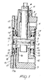
- Figure 1 is a midsectional view of a first embodiment of the invention; and
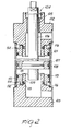
- Figure 2 is a midsectional view of a second embodiment of the invention.
- Making reference to the drawing views, in a first embodiment of the invention shown in Figure 1, this cylinder comprises a cylindrical body, for example formed from a length of ground tube, and two heads or end caps which are identified, for convenience sake, as an
upper end cap 2 andlower end cap 3. - The
upper end cap 2 has anaxial bore 4 provided with aseal 5, wherethrough arod 6 of a piston 7 is slidably passed which piston forms a seal with the inner wall of the cylindrical body 1 by means of an 0-ring 8. - The piston 7 defines, inside the cylindrical body 1, two chambers, an upper one 9 and lower one 10, respectively, which are communicated, through the respective end caps, to upper 11 and lower 12 fittings wherethrough the connection to an oil or gas source is established.
- In the embodiment shown in Figure 1, the
heads - In actual practice, a
rectangular cross-section ring 13 is provided which is locked within the cylindrical body 1 by amechanical retainer 14 partly inserted in an annular groove formed in the inside surface of the cylindrical body 1 and projecting inwardly therefrom. - The
ring 13 has a plurality of threaded, non- throughgoing ,holes 15 extending with their axes parallel to the centerline of the cylindrical body 1. - The
lower end cap 3, whereto this description refers, is rigidly connected with an inner hollowcylindrical body 16 extending parallel to the cylindrical body 1 and having an outer diameter dimension which leaves an anna- lar space from the cylindrical body 1, said space being occupied by thering 13. - Plural throughgoing
screws 17, threaded through theholes 15 in thering 13, pull the cylindrical body 1 against anabutment 18 on theend cap 3, thus causing thering 13 to act on themechanical retainer 14. - A reliable and firm connection can be established, therefore, between the
end cap 3 and cylindrical body 1. - To also provide a fluid tight seal, the
ring 13 has an external annular groove with an .0-ring 19 facing the cylindrical body 1, and an additional in,per annular groove with an O-ring seal 20 facing theelement 16. - Said seal and connection are duplicated for the
upper end cap 2, where equivalent parts have been designated with the same reference numerals. - It may be appreciated from the foregoing that this cylinder is specially simple construction-wise, as simple are the assembly and disassembly procedures therefor.
- Nothing stands outside because all the component parts are contained within the cylinder outline.
- In a second embodiment shown in Figure 2, the invention still comprises a
cylindrical body 101 having upper 102 and lower 103 end caps or heads. - The
end cap 102 is again formed with anaxial bore 104, wherethrough apiston rod 106 is slidably passed with the interposition of aseal 105. - Rigid with the
piston rod 106 is again apiston 107, which forms a seal with the inner wall of thecylindrical body 101 by means of an 0-ring 108. - Connection of the end caps is accomplished, in the embodiment being described, by interposing, between the
cylindrical body 101 and an inner hollowcylindrical body 109 in theend cap 103, a metal ring 110 having a substantially rectangular cross-sectional configuration. - Said ring 110 has an
inside thread 111 for thread engagement on the hollowcylindrical body 109. - The
ring 10 is further formed with an additionalannular lug 112 extending towards thehead 3 and against thebody 109 for assuring a fluid tight association by means of an 0-ring seal 113 accommodated in a groove formed in the hollowcylindrical body 109. - The ring 110 is again arranged to interfere with a
mechanical retainer 114 which is partly inserted in an annular groove formed in the inside portion of thecylindrical body 101. - A further 0-
ring seal 115, inserted into a groove formed in an external surface of the ring 110, provides a fluid tight seal along the area between the ring 110 andcylindrical body 101. - In this embodiment, a tight seal is ensured by the
end caps cylindrical body 101 being threaded in to abut against a flange formation, indicated at 116, on theend cap 103. - Connection of the
upper end cap 102 is achieved in the same way as theend cap 103. - Of course the two embodiments can co-exist in a same cylinder, whereat for example the upper head is connected to the cylindrical body as shown in Figure 1, whereas the lower head is connected to the cylindrical body as shown in Figure Z or viceversa.
- It may be appreciated from the faregoing description that all of the invention objects have been achieved, and that both embodiments of the invention provide a fluid operated cylinder which is extremely simple, compact, and free of any outwardly protruding elements.
- Of course, dimensions may be selected contingent on individual cylinder design, and the materials used may be any suitable ones.
Claims (7)
Priority Applications (1)
| Application Number | Priority Date | Filing Date | Title |
|---|---|---|---|
| AT84103625T ATE40191T1 (en) | 1983-04-15 | 1984-04-02 | FLUID ACTUATED PRESSURE CYLINDER. |
Applications Claiming Priority (2)
| Application Number | Priority Date | Filing Date | Title |
|---|---|---|---|
| IT4155183 | 1983-04-15 | ||
| IT41551/83A IT1174905B (en) | 1983-04-15 | 1983-04-15 | CYLINDER FOR PRESSURIZED FLUIDS |
Publications (3)
| Publication Number | Publication Date |
|---|---|
| EP0122531A2 true EP0122531A2 (en) | 1984-10-24 |
| EP0122531A3 EP0122531A3 (en) | 1985-08-21 |
| EP0122531B1 EP0122531B1 (en) | 1989-01-18 |
Family
ID=11251039
Family Applications (1)
| Application Number | Title | Priority Date | Filing Date |
|---|---|---|---|
| EP84103625A Expired EP0122531B1 (en) | 1983-04-15 | 1984-04-02 | Pressurized fluid operated cylinder |
Country Status (6)
| Country | Link |
|---|---|
| US (1) | US4592267A (en) |
| EP (1) | EP0122531B1 (en) |
| JP (1) | JPS59205068A (en) |
| AT (1) | ATE40191T1 (en) |
| DE (1) | DE3476247D1 (en) |
| IT (1) | IT1174905B (en) |
Cited By (3)
| Publication number | Priority date | Publication date | Assignee | Title |
|---|---|---|---|---|
| DE102010055694A1 (en) * | 2010-12-22 | 2012-06-28 | Knorr-Bremse Systeme für Nutzfahrzeuge GmbH | Cover for a cylinder arrangement, cylinder arrangement and automatic transmission |
| DE102010055693A1 (en) * | 2010-12-22 | 2012-06-28 | Knorr-Bremse Systeme für Nutzfahrzeuge GmbH | Cover device for cylinder assembly for use in automatic transmission for vehicle, has cylinder, where cover is received or receivable in cylinder in partial manner for sealably covering cylindrical opening of cylinder |
| WO2015181796A1 (en) * | 2014-05-30 | 2015-12-03 | Air Torque S.P.A. | Fluid-operated linear actuator |
Families Citing this family (2)
| Publication number | Priority date | Publication date | Assignee | Title |
|---|---|---|---|---|
| US4802404A (en) * | 1987-04-06 | 1989-02-07 | Pneumo Abex Corporation | Composite cylinder assembly with removable liner assembly |
| US4926745A (en) * | 1988-04-21 | 1990-05-22 | The United States Of Amerca As Represented By The United States Department Of Energy | Pull rod assembly |
Citations (3)
| Publication number | Priority date | Publication date | Assignee | Title |
|---|---|---|---|---|
| US2737404A (en) * | 1952-12-05 | 1956-03-06 | Clark Equipment Co | Cylinder construction |
| US3113490A (en) * | 1961-03-16 | 1963-12-10 | Stanley G Harwood | Fluid motor |
| CH397432A (en) * | 1960-07-15 | 1965-08-15 | Festo Maschf Stoll G | Working cylinder for pneumatic and hydraulic pressure media |
Family Cites Families (5)
| Publication number | Priority date | Publication date | Assignee | Title |
|---|---|---|---|---|
| US2518787A (en) * | 1946-01-18 | 1950-08-15 | Vickers Inc | Cylinder construction |
| US2480633A (en) * | 1947-02-28 | 1949-08-30 | Niels A Christensen | Cylinder and cylinder head construction |
| US2973744A (en) * | 1960-03-09 | 1961-03-07 | W E Hennells Company | Cushioning structure for fluid actuated cylinder |
| US3185043A (en) * | 1962-02-13 | 1965-05-25 | Ansel W Dunham | Cylinder arrangement |
| US3219059A (en) * | 1962-04-18 | 1965-11-23 | Arthur E Williams | Dispensing valve |
-
1983
- 1983-04-15 IT IT41551/83A patent/IT1174905B/en active
-
1984
- 1984-04-02 US US06/595,890 patent/US4592267A/en not_active Expired - Fee Related
- 1984-04-02 AT AT84103625T patent/ATE40191T1/en active
- 1984-04-02 DE DE8484103625T patent/DE3476247D1/en not_active Expired
- 1984-04-02 EP EP84103625A patent/EP0122531B1/en not_active Expired
- 1984-04-13 JP JP59074810A patent/JPS59205068A/en active Pending
Patent Citations (3)
| Publication number | Priority date | Publication date | Assignee | Title |
|---|---|---|---|---|
| US2737404A (en) * | 1952-12-05 | 1956-03-06 | Clark Equipment Co | Cylinder construction |
| CH397432A (en) * | 1960-07-15 | 1965-08-15 | Festo Maschf Stoll G | Working cylinder for pneumatic and hydraulic pressure media |
| US3113490A (en) * | 1961-03-16 | 1963-12-10 | Stanley G Harwood | Fluid motor |
Cited By (5)
| Publication number | Priority date | Publication date | Assignee | Title |
|---|---|---|---|---|
| DE102010055694A1 (en) * | 2010-12-22 | 2012-06-28 | Knorr-Bremse Systeme für Nutzfahrzeuge GmbH | Cover for a cylinder arrangement, cylinder arrangement and automatic transmission |
| DE102010055693A1 (en) * | 2010-12-22 | 2012-06-28 | Knorr-Bremse Systeme für Nutzfahrzeuge GmbH | Cover device for cylinder assembly for use in automatic transmission for vehicle, has cylinder, where cover is received or receivable in cylinder in partial manner for sealably covering cylindrical opening of cylinder |
| US9334961B2 (en) | 2010-12-22 | 2016-05-10 | Knorr-Bremse Systeme Fuer Nutzfahrzeuge Gmbh | Cover for a cylinder arrangement, cylinder arrangement, and automatic transmission |
| DE102010055693B4 (en) | 2010-12-22 | 2023-05-04 | Knorr-Bremse Systeme für Nutzfahrzeuge GmbH | Cylinder assembly cover device, cylinder assembly, automatic transmission and assembling method |
| WO2015181796A1 (en) * | 2014-05-30 | 2015-12-03 | Air Torque S.P.A. | Fluid-operated linear actuator |
Also Published As
| Publication number | Publication date |
|---|---|
| US4592267A (en) | 1986-06-03 |
| IT1174905B (en) | 1987-07-01 |
| EP0122531B1 (en) | 1989-01-18 |
| DE3476247D1 (en) | 1989-02-23 |
| IT8341551A0 (en) | 1983-04-15 |
| EP0122531A3 (en) | 1985-08-21 |
| JPS59205068A (en) | 1984-11-20 |
| ATE40191T1 (en) | 1989-02-15 |
Similar Documents
| Publication | Publication Date | Title |
|---|---|---|
| US3650182A (en) | Closure for fluid pressure vessel | |
| US2597482A (en) | Joint | |
| US3306637A (en) | Reuseable hose end fitting | |
| US2742929A (en) | Pressure storage device | |
| US3321217A (en) | Coupling apparatus for well heads and the like | |
| US4894156A (en) | Hose construction, coupling arrangement therefor and method of making the same | |
| US4707262A (en) | Hose construction, coupling arrangement therefor and method of making the same | |
| US3114326A (en) | Plunger type pump especially for high pressure | |
| US3150571A (en) | Actuator | |
| US3510233A (en) | Cylinder structure for single or multistage piston compressors | |
| EP0122531A2 (en) | Pressurized fluid operated cylinder | |
| GB8915622D0 (en) | Composite pressure vessel | |
| US2410404A (en) | Valve | |
| US2856249A (en) | High-pressure pump liner and packing | |
| IE43266B1 (en) | Pipe coupling | |
| US4512496A (en) | High pressure feedwater heater closure assembly | |
| US2729244A (en) | Hydraulic accumulators | |
| US4806248A (en) | Hose construction, coupling arrangement therefor and method of making the same | |
| US3599825A (en) | Pressure vessel with seal ring construction | |
| US3685398A (en) | Hydraulic cylinder | |
| US4470340A (en) | Locking mechanism for fluid operated actuator | |
| US4208953A (en) | Plunger for compressors | |
| US3303855A (en) | Piston and spool valve assembly | |
| US3175725A (en) | Fluid motor | |
| GB2111154A (en) | Fluid flow couplings |
Legal Events
| Date | Code | Title | Description |
|---|---|---|---|
| PUAI | Public reference made under article 153(3) epc to a published international application that has entered the european phase |
Free format text: ORIGINAL CODE: 0009012 |
|
| AK | Designated contracting states |
Designated state(s): AT BE CH DE FR GB LI LU NL SE |
|
| PUAL | Search report despatched |
Free format text: ORIGINAL CODE: 0009013 |
|
| AK | Designated contracting states |
Designated state(s): AT BE CH DE FR GB LI LU NL SE |
|
| 17P | Request for examination filed |
Effective date: 19860212 |
|
| 17Q | First examination report despatched |
Effective date: 19870423 |
|
| GRAA | (expected) grant |
Free format text: ORIGINAL CODE: 0009210 |
|
| AK | Designated contracting states |
Kind code of ref document: B1 Designated state(s): AT BE CH DE FR GB LI LU NL SE |
|
| PG25 | Lapsed in a contracting state [announced via postgrant information from national office to epo] |
Ref country code: NL Effective date: 19890118 Ref country code: BE Effective date: 19890118 |
|
| REF | Corresponds to: |
Ref document number: 40191 Country of ref document: AT Date of ref document: 19890215 Kind code of ref document: T |
|
| REF | Corresponds to: |
Ref document number: 3476247 Country of ref document: DE Date of ref document: 19890223 |
|
| PGFP | Annual fee paid to national office [announced via postgrant information from national office to epo] |
Ref country code: DE Payment date: 19890406 Year of fee payment: 6 |
|
| PGFP | Annual fee paid to national office [announced via postgrant information from national office to epo] |
Ref country code: SE Payment date: 19890407 Year of fee payment: 6 |
|
| PGFP | Annual fee paid to national office [announced via postgrant information from national office to epo] |
Ref country code: FR Payment date: 19890410 Year of fee payment: 6 |
|
| ET | Fr: translation filed | ||
| PGFP | Annual fee paid to national office [announced via postgrant information from national office to epo] |
Ref country code: CH Payment date: 19890427 Year of fee payment: 6 |
|
| PG25 | Lapsed in a contracting state [announced via postgrant information from national office to epo] |
Ref country code: LU Free format text: LAPSE BECAUSE OF NON-PAYMENT OF DUE FEES Effective date: 19890430 |
|
| PGFP | Annual fee paid to national office [announced via postgrant information from national office to epo] |
Ref country code: GB Payment date: 19890430 Year of fee payment: 6 |
|
| PGFP | Annual fee paid to national office [announced via postgrant information from national office to epo] |
Ref country code: AT Payment date: 19890502 Year of fee payment: 6 |
|
| NLV1 | Nl: lapsed or annulled due to failure to fulfill the requirements of art. 29p and 29m of the patents act | ||
| PLBE | No opposition filed within time limit |
Free format text: ORIGINAL CODE: 0009261 |
|
| STAA | Information on the status of an ep patent application or granted ep patent |
Free format text: STATUS: NO OPPOSITION FILED WITHIN TIME LIMIT |
|
| 26N | No opposition filed | ||
| PG25 | Lapsed in a contracting state [announced via postgrant information from national office to epo] |
Ref country code: GB Effective date: 19900402 Ref country code: AT Effective date: 19900402 |
|
| PG25 | Lapsed in a contracting state [announced via postgrant information from national office to epo] |
Ref country code: SE Effective date: 19900403 |
|
| PG25 | Lapsed in a contracting state [announced via postgrant information from national office to epo] |
Ref country code: LI Effective date: 19900430 Ref country code: CH Effective date: 19900430 |
|
| GBPC | Gb: european patent ceased through non-payment of renewal fee | ||
| PG25 | Lapsed in a contracting state [announced via postgrant information from national office to epo] |
Ref country code: FR Effective date: 19901228 |
|
| REG | Reference to a national code |
Ref country code: CH Ref legal event code: PL |
|
| PG25 | Lapsed in a contracting state [announced via postgrant information from national office to epo] |
Ref country code: DE Effective date: 19910101 |
|
| REG | Reference to a national code |
Ref country code: FR Ref legal event code: ST |
|
| EUG | Se: european patent has lapsed |
Ref document number: 84103625.4 Effective date: 19910115 |