EP0121668A2 - Solar heat accumulating greenhouses - Google Patents
Solar heat accumulating greenhouses Download PDFInfo
- Publication number
- EP0121668A2 EP0121668A2 EP84101024A EP84101024A EP0121668A2 EP 0121668 A2 EP0121668 A2 EP 0121668A2 EP 84101024 A EP84101024 A EP 84101024A EP 84101024 A EP84101024 A EP 84101024A EP 0121668 A2 EP0121668 A2 EP 0121668A2
- Authority
- EP
- European Patent Office
- Prior art keywords
- greenhouse
- heat accumulating
- air
- buried
- ground
- Prior art date
- Legal status (The legal status is an assumption and is not a legal conclusion. Google has not performed a legal analysis and makes no representation as to the accuracy of the status listed.)
- Granted
Links
Images
Classifications
-
- A—HUMAN NECESSITIES
- A01—AGRICULTURE; FORESTRY; ANIMAL HUSBANDRY; HUNTING; TRAPPING; FISHING
- A01G—HORTICULTURE; CULTIVATION OF VEGETABLES, FLOWERS, RICE, FRUIT, VINES, HOPS OR SEAWEED; FORESTRY; WATERING
- A01G9/00—Cultivation in receptacles, forcing-frames or greenhouses; Edging for beds, lawn or the like
- A01G9/24—Devices or systems for heating, ventilating, regulating temperature, illuminating, or watering, in greenhouses, forcing-frames, or the like
- A01G9/243—Collecting solar energy
-
- F—MECHANICAL ENGINEERING; LIGHTING; HEATING; WEAPONS; BLASTING
- F28—HEAT EXCHANGE IN GENERAL
- F28D—HEAT-EXCHANGE APPARATUS, NOT PROVIDED FOR IN ANOTHER SUBCLASS, IN WHICH THE HEAT-EXCHANGE MEDIA DO NOT COME INTO DIRECT CONTACT
- F28D20/00—Heat storage plants or apparatus in general; Regenerative heat-exchange apparatus not covered by groups F28D17/00 or F28D19/00
- F28D20/02—Heat storage plants or apparatus in general; Regenerative heat-exchange apparatus not covered by groups F28D17/00 or F28D19/00 using latent heat
- F28D20/023—Heat storage plants or apparatus in general; Regenerative heat-exchange apparatus not covered by groups F28D17/00 or F28D19/00 using latent heat the latent heat storage material being enclosed in granular particles or dispersed in a porous, fibrous or cellular structure
-
- Y—GENERAL TAGGING OF NEW TECHNOLOGICAL DEVELOPMENTS; GENERAL TAGGING OF CROSS-SECTIONAL TECHNOLOGIES SPANNING OVER SEVERAL SECTIONS OF THE IPC; TECHNICAL SUBJECTS COVERED BY FORMER USPC CROSS-REFERENCE ART COLLECTIONS [XRACs] AND DIGESTS
- Y02—TECHNOLOGIES OR APPLICATIONS FOR MITIGATION OR ADAPTATION AGAINST CLIMATE CHANGE
- Y02A—TECHNOLOGIES FOR ADAPTATION TO CLIMATE CHANGE
- Y02A40/00—Adaptation technologies in agriculture, forestry, livestock or agroalimentary production
- Y02A40/10—Adaptation technologies in agriculture, forestry, livestock or agroalimentary production in agriculture
- Y02A40/25—Greenhouse technology, e.g. cooling systems therefor
-
- Y—GENERAL TAGGING OF NEW TECHNOLOGICAL DEVELOPMENTS; GENERAL TAGGING OF CROSS-SECTIONAL TECHNOLOGIES SPANNING OVER SEVERAL SECTIONS OF THE IPC; TECHNICAL SUBJECTS COVERED BY FORMER USPC CROSS-REFERENCE ART COLLECTIONS [XRACs] AND DIGESTS
- Y02—TECHNOLOGIES OR APPLICATIONS FOR MITIGATION OR ADAPTATION AGAINST CLIMATE CHANGE
- Y02B—CLIMATE CHANGE MITIGATION TECHNOLOGIES RELATED TO BUILDINGS, e.g. HOUSING, HOUSE APPLIANCES OR RELATED END-USER APPLICATIONS
- Y02B10/00—Integration of renewable energy sources in buildings
- Y02B10/20—Solar thermal
-
- Y—GENERAL TAGGING OF NEW TECHNOLOGICAL DEVELOPMENTS; GENERAL TAGGING OF CROSS-SECTIONAL TECHNOLOGIES SPANNING OVER SEVERAL SECTIONS OF THE IPC; TECHNICAL SUBJECTS COVERED BY FORMER USPC CROSS-REFERENCE ART COLLECTIONS [XRACs] AND DIGESTS
- Y02—TECHNOLOGIES OR APPLICATIONS FOR MITIGATION OR ADAPTATION AGAINST CLIMATE CHANGE
- Y02E—REDUCTION OF GREENHOUSE GAS [GHG] EMISSIONS, RELATED TO ENERGY GENERATION, TRANSMISSION OR DISTRIBUTION
- Y02E60/00—Enabling technologies; Technologies with a potential or indirect contribution to GHG emissions mitigation
- Y02E60/14—Thermal energy storage
-
- Y—GENERAL TAGGING OF NEW TECHNOLOGICAL DEVELOPMENTS; GENERAL TAGGING OF CROSS-SECTIONAL TECHNOLOGIES SPANNING OVER SEVERAL SECTIONS OF THE IPC; TECHNICAL SUBJECTS COVERED BY FORMER USPC CROSS-REFERENCE ART COLLECTIONS [XRACs] AND DIGESTS
- Y02—TECHNOLOGIES OR APPLICATIONS FOR MITIGATION OR ADAPTATION AGAINST CLIMATE CHANGE
- Y02E—REDUCTION OF GREENHOUSE GAS [GHG] EMISSIONS, RELATED TO ENERGY GENERATION, TRANSMISSION OR DISTRIBUTION
- Y02E70/00—Other energy conversion or management systems reducing GHG emissions
- Y02E70/30—Systems combining energy storage with energy generation of non-fossil origin
-
- Y—GENERAL TAGGING OF NEW TECHNOLOGICAL DEVELOPMENTS; GENERAL TAGGING OF CROSS-SECTIONAL TECHNOLOGIES SPANNING OVER SEVERAL SECTIONS OF THE IPC; TECHNICAL SUBJECTS COVERED BY FORMER USPC CROSS-REFERENCE ART COLLECTIONS [XRACs] AND DIGESTS
- Y02—TECHNOLOGIES OR APPLICATIONS FOR MITIGATION OR ADAPTATION AGAINST CLIMATE CHANGE
- Y02P—CLIMATE CHANGE MITIGATION TECHNOLOGIES IN THE PRODUCTION OR PROCESSING OF GOODS
- Y02P60/00—Technologies relating to agriculture, livestock or agroalimentary industries
- Y02P60/12—Technologies relating to agriculture, livestock or agroalimentary industries using renewable energies, e.g. solar water pumping
Definitions
- This invention relates to solar heat accumulating greenhouses.
- a solar heat accumulating greenhouse having a heat accumulating tank buried in the ground within the greenhouse, an air discharge pipe open towards the lower portion in the greenhouse and an air suction pipe open towards the upper portion of the greenhouse having an air circulating fan on the way; characterised in that a large number of air blast pipes extending through a cover of heat conducting material are buried in the ground.
- an extremely high heat collecting efficiency is achieved so as to accumulate extra heat, which may be discharged during night time or in rainy weather, and therefore, the temperature within the greenhouse can be maintained at a required level, without employment of other heating facilities and therefore avoiding fuel cost and thus contributing to energy saving and saving of expense.
- the plant culture soil is also heated simultaneously with the air within the greenhouse, growth of plants may be expedited still further as compared with greenhouses conventionally proposed.
- the greenhouse 5A has,buried in the ground within the greenhouse 5A, a latent heat accumulating tank 5B including a heat insulating box-like member 501 having a corrosion-resistance surface, and a cover member 502 made, for example, of a metallic material having superior corrosion resistance and heat conduction applied on the upper surface of the box-like member 501.
- the cover member 502 is provided with a large number of blast pipes 521 extending upwardly from the cover member 502, each of which blast pipes 521 is further covered by a hood member 522 having a plurality of through-holes 522a directed in a horizontal direction as is most clearly seen in Figure 2.
- the cover member 502 is provided with a plurality of shallow water discharge grooves 523 arranged in parallel relation to each other.
- the interior of the latent heat accumulating tank 5B is partitioned into a plurality of sections 5B 1 , 5B 2 , across, and 5B by partition members 503 of a coarse mesh-like structure.
- a large number of heat accumulating members 5S each being a capsule, for example, of a spherical shape or tetrapod-like configuration, or being a spherical container or capsule of any other desired shape, having a heat conducting body with a fill of latent heat accumulating substance, are accommodated under the state where a large amount of gaps are provided therebetween.
- an air discharge pipe 504 open towards the lower portion in the greenhouse 5A and an air suction pipe 505 open at the upper central portion in the greenhouse are connected in a symmetrical relation with each other.
- an air collector 5C made of glass or metallic material having sufficient solar heat absorbing ability and corrosion resistance is installed, and is connected, as a by-pass, to the upstream side suction pipe 505 along the air flow of the air circulating fan 506.
- air plugs 505a and 507a are respectively inserted for change-over of the air passage.
- the upper portion of the latent heat accumulating tank 5B is covered by plant culture soil 508 to such an extent as the blast pipe hoods 522 are buried therein.
- plant culture soil 508 soil of coarse particles is particularly employed so that the soil may not enter the interior of the hoods via the through-holes 522a of the hoods 522.
- plants 5D are raised.
- the air valve 505a at the side of the suction pipe is opened, and the air valve 507a at the side of the air collector is closed as to form the air circulating system between the interior of the greenhouse and the latent heat accumulating tank 5B, and thus, the air within the greenhouse drawn in from the air suction pipe 505 is introudced into the latent heat accumulating tank 5B to be heated, in the tank, by receiving the heat radiating action of the heat accumulating members 5S, and is discharged into the greenhouse and the soil for heating in the similar manner as in the day time.
- the heat radiation into the culture soil 508 may also be effected through the heat conduction by the cover member 502.
- the water discharge grooves 523 are arranged to collect surplus water for discharging it out of the greenhouse during irrigation. By the above arrangement, there is no possibility that water enters from the blast pipes 521 into the heat accumulating tank 5B.
- the fill of latent heat accumulating substance in the heat accumulating members 5S can be CaCl 2 . 6H 2 O; Na 2 SO 4 .10H20; Na 2 SO 3 ⁇ 5H 2 0; paraffin etc.
Landscapes
- Engineering & Computer Science (AREA)
- Life Sciences & Earth Sciences (AREA)
- Dispersion Chemistry (AREA)
- Sustainable Energy (AREA)
- Environmental Sciences (AREA)
- Chemical & Material Sciences (AREA)
- Sustainable Development (AREA)
- Physics & Mathematics (AREA)
- Thermal Sciences (AREA)
- Mechanical Engineering (AREA)
- General Engineering & Computer Science (AREA)
- Greenhouses (AREA)
- Central Heating Systems (AREA)
- Cultivation Of Plants (AREA)
Abstract
Description
- This invention relates to solar heat accumulating greenhouses.
- Conventionally, in greenhouses such as shown in Japanese Patent Kokai 54-91444, double roofs constructed with two glass panes, solar heat receiving panels arranged in the double roofs, a water storage tank storing hot water from the panels and an air conditioner using the hot water from the tank are provided. In another example as shown in Japanese Utility Model Kokai 55-56570, a heat collector and a heat accumulating tank connected to the heat collector via a fan are provided. The former has the disadvantage that the double roof is necessary for arranging panels having wide heat receiving area near the roof of the greenhouse, and is thus costly to manufacture. In both of them only the air in the greenhouse is warmed, not the soil itself directly.
- According to the present invention there is provided a solar heat accumulating greenhouse having a heat accumulating tank buried in the ground within the greenhouse, an air discharge pipe open towards the lower portion in the greenhouse and an air suction pipe open towards the upper portion of the greenhouse having an air circulating fan on the way; characterised in that a large number of air blast pipes extending through a cover of heat conducting material are buried in the ground. In this greenhouse, during sun shining hours in the day time, an extremely high heat collecting efficiency is achieved so as to accumulate extra heat, which may be discharged during night time or in rainy weather, and therefore, the temperature within the greenhouse can be maintained at a required level, without employment of other heating facilities and therefore avoiding fuel cost and thus contributing to energy saving and saving of expense. Particularly, since the plant culture soil is also heated simultaneously with the air within the greenhouse, growth of plants may be expedited still further as compared with greenhouses conventionally proposed.
- For a better understanding of the invention and to show how the same may be carried into effect, reference will now be made, by way of example,to the accompanying drawings in which:-
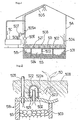
- Figure 1 is a front view, partly broken away, of a solar heat accumulating greenhouse, and
- Figure 2 is a front view in section showing, on an enlarged scale, part of the greenhouse of Figure 1.
- The
greenhouse 5A has,buried in the ground within thegreenhouse 5A, a latentheat accumulating tank 5B including a heat insulating box-like member 501 having a corrosion-resistance surface, and acover member 502 made, for example, of a metallic material having superior corrosion resistance and heat conduction applied on the upper surface of the box-like member 501. Thecover member 502 is provided with a large number ofblast pipes 521 extending upwardly from thecover member 502, each of whichblast pipes 521 is further covered by ahood member 522 having a plurality of through-holes 522a directed in a horizontal direction as is most clearly seen in Figure 2. Thecover member 502 is provided with a plurality of shallowwater discharge grooves 523 arranged in parallel relation to each other. - The interior of the latent
heat accumulating tank 5B is partitioned into a plurality of sections 5B 1, 5B2,....., and 5B bypartition members 503 of a coarse mesh-like structure. In the latentheat accumulating tank 5B a large number ofheat accumulating members 5S each being a capsule, for example, of a spherical shape or tetrapod-like configuration, or being a spherical container or capsule of any other desired shape, having a heat conducting body with a fill of latent heat accumulating substance, are accommodated under the state where a large amount of gaps are provided therebetween. - To the latent
heat accumulating tank 5B anair discharge pipe 504 open towards the lower portion in thegreenhouse 5A and anair suction pipe 505 open at the upper central portion in the greenhouse are connected in a symmetrical relation with each other. At the lower portion on the way of theair suction pipe 505, there is provided anair circulating fan 506. At the south side outside the greenhouse, anair collector 5C made of glass or metallic material having sufficient solar heat absorbing ability and corrosion resistance is installed, and is connected, as a by-pass, to the upstreamside suction pipe 505 along the air flow of theair circulating fan 506. In the course of thesuction pipe 505 and an air collector lead-inpipe 507,air plugs 505a and 507a are respectively inserted for change-over of the air passage. - The upper portion of the latent
heat accumulating tank 5B is covered byplant culture soil 508 to such an extent as theblast pipe hoods 522 are buried therein. For the culture soil provided around theblast pipe hoods 522, soil of coarse particles is particularly employed so that the soil may not enter the interior of the hoods via the through-holes 522a of thehoods 522. In theplant culture soil 508,plants 5D are raised. - By the above arrangement, during sun shining hours in the day time, heated air in the greenhouse is led into the air collector 5c through the
suction pipe 505, and is further heated by the solar heat in the tank. The warm air is then drawn by theair circulating fan 506 into the latentheat accumulating tank 5B for heat accumulation in theheat accumulating substance 5S in the tank, and is blasted into the greenhouse through theair discharge pipe 504, with heat inertia still contained therein. Meanwhile, part of the warm air is pushed out of theblast pipes 521 for penetration into the culture soil so as to warm up side soil so as to expedite the growth of the plants. - During night time and rainy weather, the
air valve 505a at the side of the suction pipe is opened, and the air valve 507a at the side of the air collector is closed as to form the air circulating system between the interior of the greenhouse and the latentheat accumulating tank 5B, and thus, the air within the greenhouse drawn in from theair suction pipe 505 is introudced into the latentheat accumulating tank 5B to be heated, in the tank, by receiving the heat radiating action of theheat accumulating members 5S, and is discharged into the greenhouse and the soil for heating in the similar manner as in the day time. The heat radiation into theculture soil 508 may also be effected through the heat conduction by thecover member 502. - The
water discharge grooves 523 are arranged to collect surplus water for discharging it out of the greenhouse during irrigation. By the above arrangement, there is no possibility that water enters from theblast pipes 521 into theheat accumulating tank 5B. - The fill of latent heat accumulating substance in the
heat accumulating members 5S can be CaCl2. 6H2O; Na2SO4.10H20; Na2SO3· 5H20; paraffin etc.
Claims (3)
Priority Applications (1)
| Application Number | Priority Date | Filing Date | Title |
|---|---|---|---|
| EP84101024A EP0121668B1 (en) | 1981-03-13 | 1982-03-08 | Solar heat accumulating greenhouses |
Applications Claiming Priority (3)
| Application Number | Priority Date | Filing Date | Title |
|---|---|---|---|
| JP56037145A JPS57150326A (en) | 1981-03-13 | 1981-03-13 | Solar energy heat storing greenhouse |
| JP37145/81U | 1981-03-13 | ||
| EP84101024A EP0121668B1 (en) | 1981-03-13 | 1982-03-08 | Solar heat accumulating greenhouses |
Related Parent Applications (2)
| Application Number | Title | Priority Date | Filing Date |
|---|---|---|---|
| EP82900663A Division EP0073836B1 (en) | 1981-03-13 | 1982-03-08 | Latent heat accumulating greenhouses |
| EP82900663A Division-Into EP0073836B1 (en) | 1981-03-13 | 1982-03-08 | Latent heat accumulating greenhouses |
Publications (3)
| Publication Number | Publication Date |
|---|---|
| EP0121668A2 true EP0121668A2 (en) | 1984-10-17 |
| EP0121668A3 EP0121668A3 (en) | 1985-07-03 |
| EP0121668B1 EP0121668B1 (en) | 1988-05-04 |
Family
ID=12489440
Family Applications (1)
| Application Number | Title | Priority Date | Filing Date |
|---|---|---|---|
| EP84101024A Expired EP0121668B1 (en) | 1981-03-13 | 1982-03-08 | Solar heat accumulating greenhouses |
Country Status (4)
| Country | Link |
|---|---|
| EP (1) | EP0121668B1 (en) |
| JP (1) | JPS57150326A (en) |
| KR (1) | KR880000957B1 (en) |
| DE (1) | DE3278440T1 (en) |
Cited By (8)
| Publication number | Priority date | Publication date | Assignee | Title |
|---|---|---|---|---|
| GB2249623A (en) * | 1990-10-04 | 1992-05-13 | David Thomas Percival | Solar heat storage arrangement |
| WO1998004231A1 (en) * | 1996-07-31 | 1998-02-05 | Enso Forest Development Oy Ltd. | New greenhouse and cultivation method |
| NL1005459C2 (en) * | 1997-03-06 | 1998-09-08 | Mij Tot Gasvoorziening Gelders | Integrated system for energy supply and energy use in greenhouse horticulture. |
| WO2000076296A1 (en) * | 1999-06-10 | 2000-12-21 | Coöperatief Advies En Onderzoeksburo U.A. Ecofys | Closed market gardening greenhouse |
| GB2355518A (en) * | 1999-10-22 | 2001-04-25 | William Paul Cowling | Thermal storage heaters |
| KR100396028B1 (en) * | 2000-12-29 | 2003-08-27 | 이석건 | solar energy hot house using condensed heat of gravels |
| NL2000253C2 (en) | 2006-10-02 | 2008-04-04 | Harry Schmitz | Assembly of horticultural establishment and animal husbandry establishment. |
| US8839551B2 (en) | 2010-07-01 | 2014-09-23 | James J. Swann | Self-regulating greenhouse |
Families Citing this family (9)
| Publication number | Priority date | Publication date | Assignee | Title |
|---|---|---|---|---|
| JPS59106234A (en) * | 1982-12-08 | 1984-06-19 | 三井化学株式会社 | Agricultural thermal storage heating method |
| JPH0421672Y2 (en) * | 1986-04-04 | 1992-05-18 | ||
| JPH07236357A (en) * | 1994-02-28 | 1995-09-12 | Hiroaki Kaneko | Feeder for fluid material such as air or water to root of plant |
| KR200445521Y1 (en) * | 2007-04-06 | 2009-08-06 | 김영기 | Solar power heating apparatus |
| KR101251616B1 (en) * | 2010-12-22 | 2013-04-09 | 에스지티(주) | Energy save country house use greenhouse |
| CN102934597A (en) * | 2012-11-13 | 2013-02-20 | 绍兴文理学院 | Solar hot-air soil heating vegetable greenhouse |
| CN103283533A (en) * | 2013-05-23 | 2013-09-11 | 青海省农林科学院 | Solar greenhouse ridge heat recovery method |
| CN111854193B (en) * | 2019-09-24 | 2021-11-26 | 东南大学 | Integrated solar receiver-multistage heat storage system |
| CN111631052B (en) * | 2020-06-12 | 2022-04-19 | 安徽新源农业科技有限公司 | Temperature control net and method for green pepper seedling culture |
Citations (7)
| Publication number | Priority date | Publication date | Assignee | Title |
|---|---|---|---|---|
| DE625540C (en) * | 1933-09-14 | 1936-02-11 | Georg Haendle | Device for heating, watering and dewatering as well as ventilating the nutrient soil provided above a heat accumulator |
| DE955368C (en) * | 1954-01-08 | 1957-01-03 | Eugen Mayer Dipl Ing Dr Ing | Device for ventilating sown or planted material |
| US2777253A (en) * | 1952-04-30 | 1957-01-15 | W G Atkinson | System for improving growing conditions for plants and farm animals in unfavorable climates by solar energy |
| US3925928A (en) * | 1973-07-23 | 1975-12-16 | 30 Decembrie Intreprinderea | Air conditioning, soil irrigation, fertilization and pest-fighting plant for use in greenhouses |
| JPS5491444A (en) * | 1977-12-28 | 1979-07-19 | Showa Aluminium Co Ltd | Green house |
| JPS5556570U (en) * | 1978-10-13 | 1980-04-17 | ||
| US4205656A (en) * | 1978-06-06 | 1980-06-03 | Scarlata Robert W | Thermal storage reservoirs |
Family Cites Families (4)
| Publication number | Priority date | Publication date | Assignee | Title |
|---|---|---|---|---|
| JPS5029323A (en) * | 1973-07-03 | 1975-03-25 | ||
| JPS53143525A (en) * | 1977-05-13 | 1978-12-14 | Minoru Uchima | Underrground bury type regenerative device |
| JPS5912046Y2 (en) * | 1977-12-29 | 1984-04-12 | 輝男 玉井 | Soil warming device in greenhouse |
| JPS5525448U (en) * | 1978-08-09 | 1980-02-19 |
-
1981
- 1981-03-13 JP JP56037145A patent/JPS57150326A/en active Granted
-
1982
- 1982-03-08 EP EP84101024A patent/EP0121668B1/en not_active Expired
- 1982-03-08 DE DE19823278440 patent/DE3278440T1/de active Pending
-
1988
- 1988-03-19 KR KR1019880002972A patent/KR880000957B1/en not_active IP Right Cessation
Patent Citations (7)
| Publication number | Priority date | Publication date | Assignee | Title |
|---|---|---|---|---|
| DE625540C (en) * | 1933-09-14 | 1936-02-11 | Georg Haendle | Device for heating, watering and dewatering as well as ventilating the nutrient soil provided above a heat accumulator |
| US2777253A (en) * | 1952-04-30 | 1957-01-15 | W G Atkinson | System for improving growing conditions for plants and farm animals in unfavorable climates by solar energy |
| DE955368C (en) * | 1954-01-08 | 1957-01-03 | Eugen Mayer Dipl Ing Dr Ing | Device for ventilating sown or planted material |
| US3925928A (en) * | 1973-07-23 | 1975-12-16 | 30 Decembrie Intreprinderea | Air conditioning, soil irrigation, fertilization and pest-fighting plant for use in greenhouses |
| JPS5491444A (en) * | 1977-12-28 | 1979-07-19 | Showa Aluminium Co Ltd | Green house |
| US4205656A (en) * | 1978-06-06 | 1980-06-03 | Scarlata Robert W | Thermal storage reservoirs |
| JPS5556570U (en) * | 1978-10-13 | 1980-04-17 |
Cited By (11)
| Publication number | Priority date | Publication date | Assignee | Title |
|---|---|---|---|---|
| GB2249623A (en) * | 1990-10-04 | 1992-05-13 | David Thomas Percival | Solar heat storage arrangement |
| GB2249623B (en) * | 1990-10-04 | 1994-08-24 | David Thomas Percival | Direct sun store |
| WO1998004231A1 (en) * | 1996-07-31 | 1998-02-05 | Enso Forest Development Oy Ltd. | New greenhouse and cultivation method |
| NL1005459C2 (en) * | 1997-03-06 | 1998-09-08 | Mij Tot Gasvoorziening Gelders | Integrated system for energy supply and energy use in greenhouse horticulture. |
| WO1998038849A1 (en) * | 1997-03-06 | 1998-09-11 | Nv Maatschappij Tot Gasvoorziening Gelders Rivierengebied | Integrated system for energy supply and energy use in greenhouse horticulture |
| WO2000076296A1 (en) * | 1999-06-10 | 2000-12-21 | Coöperatief Advies En Onderzoeksburo U.A. Ecofys | Closed market gardening greenhouse |
| GB2355518A (en) * | 1999-10-22 | 2001-04-25 | William Paul Cowling | Thermal storage heaters |
| KR100396028B1 (en) * | 2000-12-29 | 2003-08-27 | 이석건 | solar energy hot house using condensed heat of gravels |
| NL2000253C2 (en) | 2006-10-02 | 2008-04-04 | Harry Schmitz | Assembly of horticultural establishment and animal husbandry establishment. |
| EP1908809A1 (en) | 2006-10-02 | 2008-04-09 | Harry Schmitz | Assembly of a horticultural facility and a livestock-breeding facility |
| US8839551B2 (en) | 2010-07-01 | 2014-09-23 | James J. Swann | Self-regulating greenhouse |
Also Published As
| Publication number | Publication date |
|---|---|
| JPS57150326A (en) | 1982-09-17 |
| KR880000957B1 (en) | 1988-06-04 |
| EP0121668B1 (en) | 1988-05-04 |
| EP0121668A3 (en) | 1985-07-03 |
| DE3278440T1 (en) | 1988-06-09 |
| JPS6146089B2 (en) | 1986-10-13 |
Similar Documents
| Publication | Publication Date | Title |
|---|---|---|
| EP0121668A2 (en) | Solar heat accumulating greenhouses | |
| Santamouris et al. | Passive solar agricultural greenhouses: a worldwide classification and evaluation of technologies and systems used for heating purposes | |
| US4095369A (en) | Installation for cultivating plant cultures | |
| US4237863A (en) | Solar heating system | |
| Al-Jamal | Greenhouse cooling in hot countries | |
| CN102168882A (en) | Method and apparatus for cooling ventilation air for a building | |
| US4331128A (en) | Climate-controlled building | |
| USRE31321E (en) | Solar heating system | |
| JPS6121044B2 (en) | ||
| US4258697A (en) | Pneumatic collection, storage and transfer of solar heat | |
| KR101792223B1 (en) | Solar photovoltaic system using by rooftop gardening | |
| CN108184496A (en) | A kind of ecological photovoltaic greenhouse based on rainwater comprehensive utilization | |
| Grafiadellis | Development of a passive solar system for heating greenhouses | |
| Rocamora et al. | Aspects of PV/T solar system application for ventilation needs in greenhouses | |
| US4211209A (en) | Method and apparatus for collecting and domestic use of solar heat | |
| CN100337525C (en) | Energy-saving warm house | |
| JPH0677489B2 (en) | Greenhouse heating system | |
| EP0012757B1 (en) | A method of storing thermal energy in a ground storage device | |
| Garzoli | Energy efficient greenhouses | |
| WO2001090660A1 (en) | Method of use of solar energy and appliance for implementation of this method | |
| EP0051333A1 (en) | Equipment for the absorption of solar heat | |
| US4084575A (en) | Solar heater unit | |
| Zabeltitz et al. | Greenhouse heating with sun energy-the greenhouse as collector | |
| JPS604033Y2 (en) | solar water heater | |
| CN218514941U (en) | Rainwater collecting and water retaining device for sand fixation plants |
Legal Events
| Date | Code | Title | Description |
|---|---|---|---|
| PUAI | Public reference made under article 153(3) epc to a published international application that has entered the european phase |
Free format text: ORIGINAL CODE: 0009012 |
|
| 17P | Request for examination filed |
Effective date: 19840201 |
|
| AC | Divisional application: reference to earlier application |
Ref document number: 73836 Country of ref document: EP |
|
| AK | Designated contracting states |
Designated state(s): DE FR GB NL SE |
|
| RIN1 | Information on inventor provided before grant (corrected) |
Inventor name: ITO, HAJIME Inventor name: YANO, NAOMICHI |
|
| PUAL | Search report despatched |
Free format text: ORIGINAL CODE: 0009013 |
|
| AK | Designated contracting states |
Designated state(s): DE FR GB NL SE |
|
| 17Q | First examination report despatched |
Effective date: 19860130 |
|
| D17Q | First examination report despatched (deleted) | ||
| GRAA | (expected) grant |
Free format text: ORIGINAL CODE: 0009210 |
|
| AC | Divisional application: reference to earlier application |
Ref document number: 73836 Country of ref document: EP |
|
| AK | Designated contracting states |
Kind code of ref document: B1 Designated state(s): DE FR GB NL SE |
|
| PG25 | Lapsed in a contracting state [announced via postgrant information from national office to epo] |
Ref country code: SE Effective date: 19880531 |
|
| REF | Corresponds to: |
Ref document number: 3278440 Country of ref document: DE Date of ref document: 19880609 |
|
| ET | Fr: translation filed | ||
| PLBE | No opposition filed within time limit |
Free format text: ORIGINAL CODE: 0009261 |
|
| STAA | Information on the status of an ep patent application or granted ep patent |
Free format text: STATUS: NO OPPOSITION FILED WITHIN TIME LIMIT |
|
| PGFP | Annual fee paid to national office [announced via postgrant information from national office to epo] |
Ref country code: FR Payment date: 19890321 Year of fee payment: 8 |
|
| PGFP | Annual fee paid to national office [announced via postgrant information from national office to epo] |
Ref country code: NL Payment date: 19890331 Year of fee payment: 8 Ref country code: GB Payment date: 19890331 Year of fee payment: 8 |
|
| 26N | No opposition filed | ||
| PG25 | Lapsed in a contracting state [announced via postgrant information from national office to epo] |
Ref country code: DE Effective date: 19891201 |
|
| PG25 | Lapsed in a contracting state [announced via postgrant information from national office to epo] |
Ref country code: GB Effective date: 19900308 |
|
| PG25 | Lapsed in a contracting state [announced via postgrant information from national office to epo] |
Ref country code: NL Effective date: 19901001 |
|
| GBPC | Gb: european patent ceased through non-payment of renewal fee | ||
| NLV4 | Nl: lapsed or anulled due to non-payment of the annual fee | ||
| PG25 | Lapsed in a contracting state [announced via postgrant information from national office to epo] |
Ref country code: FR Effective date: 19901130 |
|
| REG | Reference to a national code |
Ref country code: FR Ref legal event code: ST |