EP0051333A1 - Equipment for the absorption of solar heat - Google Patents
Equipment for the absorption of solar heat Download PDFInfo
- Publication number
- EP0051333A1 EP0051333A1 EP81201172A EP81201172A EP0051333A1 EP 0051333 A1 EP0051333 A1 EP 0051333A1 EP 81201172 A EP81201172 A EP 81201172A EP 81201172 A EP81201172 A EP 81201172A EP 0051333 A1 EP0051333 A1 EP 0051333A1
- Authority
- EP
- European Patent Office
- Prior art keywords
- equipment according
- heat
- foregoing
- equipment
- space
- Prior art date
- Legal status (The legal status is an assumption and is not a legal conclusion. Google has not performed a legal analysis and makes no representation as to the accuracy of the status listed.)
- Withdrawn
Links
Images
Classifications
-
- F—MECHANICAL ENGINEERING; LIGHTING; HEATING; WEAPONS; BLASTING
- F24—HEATING; RANGES; VENTILATING
- F24S—SOLAR HEAT COLLECTORS; SOLAR HEAT SYSTEMS
- F24S10/00—Solar heat collectors using working fluids
- F24S10/60—Solar heat collectors using working fluids the working fluids trickling freely over absorbing elements
-
- Y—GENERAL TAGGING OF NEW TECHNOLOGICAL DEVELOPMENTS; GENERAL TAGGING OF CROSS-SECTIONAL TECHNOLOGIES SPANNING OVER SEVERAL SECTIONS OF THE IPC; TECHNICAL SUBJECTS COVERED BY FORMER USPC CROSS-REFERENCE ART COLLECTIONS [XRACs] AND DIGESTS
- Y02—TECHNOLOGIES OR APPLICATIONS FOR MITIGATION OR ADAPTATION AGAINST CLIMATE CHANGE
- Y02E—REDUCTION OF GREENHOUSE GAS [GHG] EMISSIONS, RELATED TO ENERGY GENERATION, TRANSMISSION OR DISTRIBUTION
- Y02E10/00—Energy generation through renewable energy sources
- Y02E10/40—Solar thermal energy, e.g. solar towers
- Y02E10/44—Heat exchange systems
Definitions
- This invention relates to an equipment for the absorption of solar heat, especially an equipment in which this solar heat is absorbed by a heat-carrying fluid that transfers the absorbed heat directly or indirectly to a fluid, stored in a tank, which can consist in the actual heat-carrying fluid itself, the object being to further use this stored and thus heated fluid as such or as a means to heat machine parts, rooms and the like.
- Equipments of that kind are already known but only consist in an inclined face, heated by sunlight and along which a thin water-curtain is allowed to flow, which curtain absorbs the heat absorbed by the face and carries it along to a storage tank or the like.
- the above-mentioned face is made as dark as possible, so that it can absorb much heat, the underside of the face being isolated.
- a transparent face for instance made of glass, is provided at a small distance of the above-mentioned face.
- This invention relates to an equipment in which provisions of such a kind are made, which constitute the real object of the invention, that the efficiency of it, compared to that of known equipments, becomes very high.
- a first object of this equipment consists in the fact that the above-mentioned inclined face, as opposed to known equipments or so-called solar panels, is placed on a relatively great distance from the above-mentioned transparent face, both faces in such a way that between them a space is formed wherein the air is strongly heated by the sunlight, especially by the direct sun-rays, on the one hand, and wherein the said inclined face is heated as well, on the other hand.
- a second object of the equipment according to the invention is that the said heat-carrying fluid, which in the case of known solar panels is displaced as a water-curtain along the heat- absorbing inclined face applied in such solar panels, according to the present invention in refined form, for instance by spraying, sprinkling or the like is brought into the said space so that per unit of weight it carries along a considerably greater amount of heat than when an ordinary water-curtain is used in which, in addition, this fluid thereafter drops onto the said inclined face, occasionally absorbing some additional heat from the said inclined face while flowing away.
- the equipment according to the invention mainly consists in two faces disposed on a relatively great distance from each other, which air- and watertightly seal the space formed in-between, possibly in combination with side- walls; within this space means that allow to sprinkle or spray a heat-carrying fluid into it and means that allow to collect and carry off said fluid.
- this equipment can exist on itself, in the form of solar elements that are displaceable or not, or can be constructed as a roof-covering of houses and the like wherein in a very particular application this equipment constitutes the object of the roof of a hot-house or green-house, being able to be provided not only in the roof of such hot-house or the like, but in the walls of it as well.
- a further particular application of the device according to the invention is the use of it to collect heat, on the one hand, and to use this heat on the appropriate moment to reheat the house, hot-house or the like in question via this device, on the other hand.
- the said equipment is mainly intended for absorbing solar heat and for storing a fluid heated by this absorbed solar heat which can occasionally be used later on to heat the said space, it is clear that such equipment can as efficiently be used to cool such space with the result that the room, situated under or next to such space, house or the like is also cooled.
- the heat-carrying fluid in such a way that it carries along more heat than the heat present in the said space, room, house or the like, that is situated under or next to such space, whereby a cooling effect is brought about.
- a heat-carrying fluid can be sprinkled or sprayed, which depending on the intention is either warmer than the space in which it is introduced, or is colder, in such a way that either a heating or a cooling of this space is obtained and as a result thereof a heating or a cooling of the house, room or the like, that is situated under or next to such a space.
- a fluid that is previously lead through a suitable cooling tower, occasionally specially provided therefor, can be used for cooling
- any fluid can be used, which in the case of cooling can also originate from any cooling installation, while, if such fluid is used as a heating-element it can be formed by so-called waste waters, which carry relatively great amounts of heat as for instance in the case of waste- or cooling-waters from electric power stations, nuclear power stations and the like.
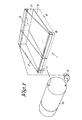
- a solar element 1 mainly consists in a transparent upper face 2; an underface 3 that is transparent or not; sidewalls 4 that are transparent or not; a supply 5 for the heatcarrying fluid and a discharge 6 for this fluid.
- the transparent upper face .2 is preferably placed obliquely with a slope that does not only secure a suitable discharge of the rain-water but is also chosen in such a way that it transmits an amount of solar radiation as large as possible.
- this face 3 is smaller than that of face 2'in order to make the distance between the upper edges of the faces 2-3 as large as possible and yet to secure an efficient discharge of the heat-carrying fluid to one side of the element.
- a pipe 5 is lead through the space, formed by the walls 2 and 4, on which several sprinklers 7 are placed that allow to bring the heat-carrying fluid in small amounts into the solar element where the heat in this element is very efficiently absorbed and carried off.
- the thus distributed fluid then falls onto the face 3 and is collected in the gutter 6 to be carried off, whereby occasio-nally, depending on the nature of the under face, which among other things is determined by the choice of material and by the colour of this face, additional heat is given up by the latter to the already heated fluid.
- Such element 1 on itself can be used to be mounted on a roof or the like, on its own or in combination with other elements, such element being able of being provided at the bottom with a suitable support 8 that is occasionally made of an isolating material.
- the pipe 5 is connected, via a pump 9, to a storage tank 10 that is also connected to the gutter 6 by means of a pipe 11.
- the heat-carrying fluid for instance water
- the heat-carrying fluid is thus pumped from the tank 10 and is brought into the element 1 via the sprinklers or spray-nozzles 7; thereafter the heat-carrying fluid automatically flows back to the lower tank 10, so forming a closed circuit.
- the thus heated fluid mostly water
- the elements according to Figure 1 are for instance used as roof-covering that is not fitted with the isolation 8, the elements can be used during the day to store heat, so that when cooling is taking place, for instance at night, the heated fluid gives up its heat to the solar elements which then via the face 3 provide heating of the room or the like involved that is covered by these elements.
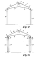
- FIG 2 an embodiment is represented whereby the solar element is in one piece and as such forms the permanent roof- covering of a house
- a possible embodiment is represented wherein the walls 12 are as well fitted with an additional inner wall 13 between which a pipe 14 with spray-nozzles or sprinklers 15 is provided and underneath a receiving gutter 16 is mounted.
- heating of the green-house will not run higher than necessary in the daytime because excessive heat is absorbed by the said heat-carrying fluid whereas, when the sun does not heat anymore, this heated fluid is used to counteract cooling of the hot-house, or to heat the hot-house.
Abstract
Equipment for absorbing solar heat, characterized in that it consists mainly of two faces (2,3) placed at a relatively large distance from each other which air- and watertightly seal the space formed in-between, occasionally in combination with side-walls (4), in said space means allowing to sprinkle or to spray a heat-carrying fluid therein, and means allowing to collect and to carry off said fluid.
Description
- This invention relates to an equipment for the absorption of solar heat, especially an equipment in which this solar heat is absorbed by a heat-carrying fluid that transfers the absorbed heat directly or indirectly to a fluid, stored in a tank, which can consist in the actual heat-carrying fluid itself, the object being to further use this stored and thus heated fluid as such or as a means to heat machine parts, rooms and the like.
- Equipments of that kind are already known but only consist in an inclined face, heated by sunlight and along which a thin water-curtain is allowed to flow, which curtain absorbs the heat absorbed by the face and carries it along to a storage tank or the like.
- In order to make the efficiency of these known equipments as favourable as possible, the above-mentioned face is made as dark as possible, so that it can absorb much heat, the underside of the face being isolated.
- At the same time a transparent face, for instance made of glass, is provided at a small distance of the above-mentioned face.
- It is known, however, that the efficiency of such equipments is extremely low so that, even with today's high fuel prices, they are economically not justified.
- This invention relates to an equipment in which provisions of such a kind are made, which constitute the real object of the invention, that the efficiency of it, compared to that of known equipments, becomes very high.
- A first object of this equipment consists in the fact that the above-mentioned inclined face, as opposed to known equipments or so-called solar panels, is placed on a relatively great distance from the above-mentioned transparent face, both faces in such a way that between them a space is formed wherein the air is strongly heated by the sunlight, especially by the direct sun-rays, on the one hand, and wherein the said inclined face is heated as well, on the other hand.
- A second object of the equipment according to the invention is that the said heat-carrying fluid, which in the case of known solar panels is displaced as a water-curtain along the heat- absorbing inclined face applied in such solar panels, according to the present invention in refined form, for instance by spraying, sprinkling or the like is brought into the said space so that per unit of weight it carries along a considerably greater amount of heat than when an ordinary water-curtain is used in which, in addition, this fluid thereafter drops onto the said inclined face, occasionally absorbing some additional heat from the said inclined face while flowing away.
- For that purpose the equipment according to the invention mainly consists in two faces disposed on a relatively great distance from each other, which air- and watertightly seal the space formed in-between, possibly in combination with side- walls; within this space means that allow to sprinkle or spray a heat-carrying fluid into it and means that allow to collect and carry off said fluid.
- It is clear that this equipment can exist on itself, in the form of solar elements that are displaceable or not, or can be constructed as a roof-covering of houses and the like wherein in a very particular application this equipment constitutes the object of the roof of a hot-house or green-house, being able to be provided not only in the roof of such hot-house or the like, but in the walls of it as well.
- A further particular application of the device according to the invention is the use of it to collect heat, on the one hand, and to use this heat on the appropriate moment to reheat the house, hot-house or the like in question via this device, on the other hand.
- Indeed, experiments have shown that it is possible to store very advantageously a great amount of heat from the sunlight during the day, at least along the roof-surface, in a heat- carrying fluid in general, and to use the heat of this heat- carrying fluid again, for instance at night to maintain or realise a determined temperature in the involved house, green-house or the like.
- Although the said equipment is mainly intended for absorbing solar heat and for storing a fluid heated by this absorbed solar heat which can occasionally be used later on to heat the said space, it is clear that such equipment can as efficiently be used to cool such space with the result that the room, situated under or next to such space, house or the like is also cooled.
- For this purpose it is sufficient to choose the heat-carrying fluid in such a way that it carries along more heat than the heat present in the said space, room, house or the like, that is situated under or next to such space, whereby a cooling effect is brought about.
- It is also clear that, either to heat or to cool as efficiently as described before, a heat-carrying fluid can be sprinkled or sprayed, which depending on the intention is either warmer than the space in which it is introduced, or is colder, in such a way that either a heating or a cooling of this space is obtained and as a result thereof a heating or a cooling of the house, room or the like, that is situated under or next to such a space.
- In a highly efficient application either a fluid that is previously lead through a suitable cooling tower, occasionally specially provided therefor, can be used for cooling, whereas in the second case any fluid can be used, which in the case of cooling can also originate from any cooling installation, while, if such fluid is used as a heating-element it can be formed by so-called waste waters, which carry relatively great amounts of heat as for instance in the case of waste- or cooling-waters from electric power stations, nuclear power stations and the like.
- Also well-water or the like can be used for this purpose.
- It is clear that in this way the enormous energy carried off by such waste waters or the like can be used very efficiently. With the purpose of better showing the characteristics of the invention a few preferred embodiments of a device according to the invention are described hereinafter in a very schematic way with reference to the accompanying drawings in which :
- Figure 1 represents in a schematic way a perspective view of an equipment in the form of a solar element according to the invention;
- Figure 2 represents in a schematic way a vertical cross- section of a house, green-house or the like of which the roof has been designed in accordance with the invention;
- Figure 3 represents an alternative of Figure 2.
- As represented in Figure 1 a solar element 1 according to the invention mainly consists in a transparent
upper face 2; anunderface 3 that is transparent or not;sidewalls 4 that are transparent or not; a supply 5 for the heatcarrying fluid and adischarge 6 for this fluid. - The transparent upper face .2 is preferably placed obliquely with a slope that does not only secure a suitable discharge of the rain-water but is also chosen in such a way that it transmits an amount of solar radiation as large as possible.
- The under
face 3, which can be made of any material, is parallel to theupper face 2 or is not. - In a preferred embodiment, however, the slope of this
face 3 is smaller than that of face 2'in order to make the distance between the upper edges of the faces 2-3 as large as possible and yet to secure an efficient discharge of the heat-carrying fluid to one side of the element. - At least in one place and preferably as high as possible a pipe 5 is lead through the space, formed by the
walls several sprinklers 7 are placed that allow to bring the heat-carrying fluid in small amounts into the solar element where the heat in this element is very efficiently absorbed and carried off. - .The thus distributed fluid then falls onto the
face 3 and is collected in thegutter 6 to be carried off, whereby occasio-nally, depending on the nature of the under face, which among other things is determined by the choice of material and by the colour of this face, additional heat is given up by the latter to the already heated fluid. - Such element 1 on itself can be used to be mounted on a roof or the like, on its own or in combination with other elements, such element being able of being provided at the bottom with a suitable support 8 that is occasionally made of an isolating material.
- As represented in Figure 1 the pipe 5 is connected, via a
pump 9, to astorage tank 10 that is also connected to thegutter 6 by means of a pipe 11. - The heat-carrying fluid, for instance water, is thus pumped from the
tank 10 and is brought into the element 1 via the sprinklers or spray-nozzles 7; thereafter the heat-carrying fluid automatically flows back to thelower tank 10, so forming a closed circuit. - The thus heated fluid, mostly water, can then be used either for household applications, or for heating tools, rooms or the like, the heat-carrying fluid being used directly or indirectly.
- When the elements according to Figure 1 are for instance used as roof-covering that is not fitted with the isolation 8, the elements can be used during the day to store heat, so that when cooling is taking place, for instance at night, the heated fluid gives up its heat to the solar elements which then via the
face 3 provide heating of the room or the like involved that is covered by these elements. - In Figure 2 an embodiment is represented whereby the solar element is in one piece and as such forms the permanent roof- covering of a house, whereas in Figure 3 a possible embodiment is represented wherein the
walls 12 are as well fitted with an additionalinner wall 13 between which apipe 14 with spray-nozzles orsprinklers 15 is provided and underneath a receiving gutter 16 is mounted. - Needless to say that such equipment according to the embodiment in the form of juxtaposed elements as well as in the form represented in the Figures 2 and 3 can extremely efficiently be used in hot-houses and green-houses.
- Indeed here, as is known, at least during the night some additional heating for maintaining a suitable temperature is necessary, whereas during the day in most cases ventilation windows have to be opened to carry off the heat and to keep both temperature and degree of humidity at a suitable level whereby much heat is lost.
- Well, according to the invention heating of the green-house will not run higher than necessary in the daytime because excessive heat is absorbed by the said heat-carrying fluid whereas, when the sun does not heat anymore, this heated fluid is used to counteract cooling of the hot-house, or to heat the hot-house.
- It is clear that in the case of such special application the nature of the faces has to be determined precisely in order to obtain that the heat remains trapped to a maximum degree, and that any radiation necessary for a suitable plant-growth is transmitted as well.
- Evidently, the present invention is not limited to the embodiments described as examples and represented in the accompanying drawings, but the equipment or solar element according to the invention can be realised in many different forms and dimensions without departing from the scope of the invention.
Claims (15)
1.- Equipment for absorbing solar heat, characterized in that it consists mainly of two faces (2-3) placed at a relatively large distance from each other which air- and watertightly seal the space formed in-between, occasionally in combination with side-walls (4), in said space means allowing to sprinkle or to spray a heat-carrying fluid therein, and means allowing to collect and to carry off said fluid.
2.- Equipment according to claim l, characterized in that both said faces (2-3) are inclined.
3.- Equipment according to any of claims 1 and 2, characterized in that a distance remains at the bottom between both faces (2-3) which is sufficient for freely carrying off the heat-carrying fluid, whereas towards the top the said faces (2-3) strongly diverge.
4.- Equipment according to any of the foregoing claims, characterized in that at least in the highest part of said space a pipe (5) is provided extending preferably over its whole length and which at regular distances carries sprinklers or spray nozzles (7).
5.- Equipment according to any of the foregoing claims, characterized in that a discharge gutter (6) is provided at the place where the said faces (2-3) are the closest to one another under the bottom face.
6.- Equipment according to any of the foregoing claims, characterized in that the top face (2) is made of a transparent material.
7.- Equipment according to any of the foregoing claims, characterized in that the bottom face (3) is made of a transparent or at least light-transmitting material.
8.- Equipment according to any of the foregoing claims, characterized in that the heat-carrying fluid is water.
9.- Equipment according to any of the foregoing claims, characterized in that it is formed by loose elements (1) with limited surface area, which occasionally can be placed in one another's extension.
10.- Equipment according to claim 9, characterized in that an isolating layer (8) is provided under each element.
11.- Equipment according to any of claims 1 to 8, characterized in that it forms the actual roofcovering of a house, green-house or the like.
12.- Equipment according to any of the foregoing claims, characterized in that the said pipe (5) is connected to a storage tank (10) having sprinklers or spray nozzles (7), said pipe being provided with a pump (9), whereas said gutter (6) is also connected to the said tank (10) by means of a second pipe (11).
13.- Equipment for absorbing solar heat according to any of the foregoing claims, characterized in that it can be used as cooling device.
14.- Equipment according to claim 13, characterized in that the heat-carrying fluid comes from a cooling tower or the like.
15.- Equipment for absorbing solar heat according to any of the foregoing claims, characterized in that for heating or cooling the abovesaid space use is made of waste waters, well-water or the like, whose temperature is higher or lower than the temperature in the said space.
Applications Claiming Priority (4)
| Application Number | Priority Date | Filing Date | Title |
|---|---|---|---|
| BE2058837 | 1980-10-31 | ||
| BE2058837 | 1980-10-31 | ||
| BE2058858 | 1980-11-18 | ||
| BE2058858 | 1980-11-18 |
Publications (1)
| Publication Number | Publication Date |
|---|---|
| EP0051333A1 true EP0051333A1 (en) | 1982-05-12 |
Family
ID=25661750
Family Applications (1)
| Application Number | Title | Priority Date | Filing Date |
|---|---|---|---|
| EP81201172A Withdrawn EP0051333A1 (en) | 1980-10-31 | 1981-10-22 | Equipment for the absorption of solar heat |
Country Status (3)
| Country | Link |
|---|---|
| EP (1) | EP0051333A1 (en) |
| DK (1) | DK480481A (en) |
| PT (1) | PT73909B (en) |
Cited By (4)
| Publication number | Priority date | Publication date | Assignee | Title |
|---|---|---|---|---|
| FR2521707A1 (en) * | 1982-02-12 | 1983-08-19 | Sorelec | Solar heat-exchanger - comprises central tube conveying heat transfer fluid surrounded by cylinder of plastic material |
| FR2558313A1 (en) * | 1984-01-13 | 1985-07-19 | Cercle Loic | Anti-brown out device. |
| GB2180636A (en) * | 1985-09-19 | 1987-04-01 | Michel Said Achou | Cooling systems |
| NL1019482C2 (en) * | 2001-12-04 | 2003-06-06 | Microtech Nederland B V | Sunscreen and cooling device for area beneath transparent sloping roof section, allows liquid to flow down slope in open air by gravity |
Citations (5)
| Publication number | Priority date | Publication date | Assignee | Title |
|---|---|---|---|---|
| US3314415A (en) * | 1964-05-01 | 1967-04-18 | Richard J Rowekamp | Structural modifications to a pooltype solar collector |
| DE7905382U1 (en) * | 1979-02-26 | 1979-07-26 | Reinhold, Bruno, 5411 Eitelborn | GREENHOUSE WITH AIR CONDITIONING |
| EP0005103A1 (en) * | 1978-04-13 | 1979-10-31 | COMMISSARIAT A L'ENERGIE ATOMIQUE Etablissement de Caractère Scientifique Technique et Industriel | Process and apparatus for the air conditioning of greenhouses with salt water and for the distillation of such water |
| US4173212A (en) * | 1977-10-17 | 1979-11-06 | The Board of Regents for the Oklahoma Agricultural and Mechanical Colleges | Self-contained solar greenhouse |
| GB2031580A (en) * | 1978-09-15 | 1980-04-23 | Novex Foreign Trade Co Ltd | Utilizing natural energy to heat a double-walled structure |
-
1981
- 1981-10-22 EP EP81201172A patent/EP0051333A1/en not_active Withdrawn
- 1981-10-30 DK DK480481A patent/DK480481A/en unknown
- 1981-10-30 PT PT73909A patent/PT73909B/en unknown
Patent Citations (5)
| Publication number | Priority date | Publication date | Assignee | Title |
|---|---|---|---|---|
| US3314415A (en) * | 1964-05-01 | 1967-04-18 | Richard J Rowekamp | Structural modifications to a pooltype solar collector |
| US4173212A (en) * | 1977-10-17 | 1979-11-06 | The Board of Regents for the Oklahoma Agricultural and Mechanical Colleges | Self-contained solar greenhouse |
| EP0005103A1 (en) * | 1978-04-13 | 1979-10-31 | COMMISSARIAT A L'ENERGIE ATOMIQUE Etablissement de Caractère Scientifique Technique et Industriel | Process and apparatus for the air conditioning of greenhouses with salt water and for the distillation of such water |
| GB2031580A (en) * | 1978-09-15 | 1980-04-23 | Novex Foreign Trade Co Ltd | Utilizing natural energy to heat a double-walled structure |
| DE7905382U1 (en) * | 1979-02-26 | 1979-07-26 | Reinhold, Bruno, 5411 Eitelborn | GREENHOUSE WITH AIR CONDITIONING |
Cited By (5)
| Publication number | Priority date | Publication date | Assignee | Title |
|---|---|---|---|---|
| FR2521707A1 (en) * | 1982-02-12 | 1983-08-19 | Sorelec | Solar heat-exchanger - comprises central tube conveying heat transfer fluid surrounded by cylinder of plastic material |
| FR2558313A1 (en) * | 1984-01-13 | 1985-07-19 | Cercle Loic | Anti-brown out device. |
| GB2180636A (en) * | 1985-09-19 | 1987-04-01 | Michel Said Achou | Cooling systems |
| GB2180636B (en) * | 1985-09-19 | 1989-12-13 | Michel Said Achou | Cooling systems |
| NL1019482C2 (en) * | 2001-12-04 | 2003-06-06 | Microtech Nederland B V | Sunscreen and cooling device for area beneath transparent sloping roof section, allows liquid to flow down slope in open air by gravity |
Also Published As
| Publication number | Publication date |
|---|---|
| DK480481A (en) | 1982-05-01 |
| PT73909A (en) | 1981-11-01 |
| PT73909B (en) | 1983-02-01 |
Similar Documents
| Publication | Publication Date | Title |
|---|---|---|
| US4271826A (en) | Device for collecting solar energy | |
| US4108373A (en) | Method and an installation for the air-conditioning of greenhouses and frames | |
| Santamouris et al. | Passive solar agricultural greenhouses: a worldwide classification and evaluation of technologies and systems used for heating purposes | |
| Erell | Roof cooling techniques: a design handbook | |
| JP2010502022A (en) | Solar equipment | |
| US4290415A (en) | Building for cold districts | |
| US4237863A (en) | Solar heating system | |
| US4249520A (en) | Pyramidal energy collector system | |
| US4331128A (en) | Climate-controlled building | |
| US4132221A (en) | Pyramidal solar heating system | |
| EP0121668B1 (en) | Solar heat accumulating greenhouses | |
| US3270739A (en) | Solar heater | |
| US4121568A (en) | Solar panel flat plate collector | |
| USRE31321E (en) | Solar heating system | |
| US4173253A (en) | Solar radiation collector and water cooler | |
| EP0051333A1 (en) | Equipment for the absorption of solar heat | |
| DE3740618C2 (en) | ||
| US4196718A (en) | Energy conservation | |
| US10972043B2 (en) | Silver lining liquid-layer solar array | |
| US4211209A (en) | Method and apparatus for collecting and domestic use of solar heat | |
| GB2259231A (en) | Renewable energy plant propagator | |
| US4446852A (en) | Terraced solar energy collector | |
| JPS62101086A (en) | Solar battery cooling system | |
| US4159711A (en) | Solar heating apparatus | |
| CN218492875U (en) | Roof heat-insulation waterproof device |
Legal Events
| Date | Code | Title | Description |
|---|---|---|---|
| PUAI | Public reference made under article 153(3) epc to a published international application that has entered the european phase |
Free format text: ORIGINAL CODE: 0009012 |
|
| AK | Designated contracting states |
Designated state(s): AT CH DE FR GB IT LU NL SE |
|
| 17P | Request for examination filed |
Effective date: 19821111 |
|
| STAA | Information on the status of an ep patent application or granted ep patent |
Free format text: STATUS: THE APPLICATION IS DEEMED TO BE WITHDRAWN |
|
| 18D | Application deemed to be withdrawn |
Effective date: 19831018 |