EP0121630A2 - Improved austenitic stainless steel alloys for high temperature applications - Google Patents
Improved austenitic stainless steel alloys for high temperature applications Download PDFInfo
- Publication number
- EP0121630A2 EP0121630A2 EP83307474A EP83307474A EP0121630A2 EP 0121630 A2 EP0121630 A2 EP 0121630A2 EP 83307474 A EP83307474 A EP 83307474A EP 83307474 A EP83307474 A EP 83307474A EP 0121630 A2 EP0121630 A2 EP 0121630A2
- Authority
- EP
- European Patent Office
- Prior art keywords
- alloy
- phosphorus
- boron
- plus
- sum
- Prior art date
- Legal status (The legal status is an assumption and is not a legal conclusion. Google has not performed a legal analysis and makes no representation as to the accuracy of the status listed.)
- Granted
Links
Images

Classifications
-
- C—CHEMISTRY; METALLURGY
- C22—METALLURGY; FERROUS OR NON-FERROUS ALLOYS; TREATMENT OF ALLOYS OR NON-FERROUS METALS
- C22C—ALLOYS
- C22C38/00—Ferrous alloys, e.g. steel alloys
- C22C38/18—Ferrous alloys, e.g. steel alloys containing chromium
- C22C38/40—Ferrous alloys, e.g. steel alloys containing chromium with nickel
- C22C38/58—Ferrous alloys, e.g. steel alloys containing chromium with nickel with more than 1.5% by weight of manganese
-
- G—PHYSICS
- G21—NUCLEAR PHYSICS; NUCLEAR ENGINEERING
- G21C—NUCLEAR REACTORS
- G21C3/00—Reactor fuel elements and their assemblies; Selection of substances for use as reactor fuel elements
- G21C3/02—Fuel elements
- G21C3/04—Constructional details
- G21C3/06—Casings; Jackets
- G21C3/07—Casings; Jackets characterised by their material, e.g. alloys
-
- Y—GENERAL TAGGING OF NEW TECHNOLOGICAL DEVELOPMENTS; GENERAL TAGGING OF CROSS-SECTIONAL TECHNOLOGIES SPANNING OVER SEVERAL SECTIONS OF THE IPC; TECHNICAL SUBJECTS COVERED BY FORMER USPC CROSS-REFERENCE ART COLLECTIONS [XRACs] AND DIGESTS
- Y02—TECHNOLOGIES OR APPLICATIONS FOR MITIGATION OR ADAPTATION AGAINST CLIMATE CHANGE
- Y02E—REDUCTION OF GREENHOUSE GAS [GHG] EMISSIONS, RELATED TO ENERGY GENERATION, TRANSMISSION OR DISTRIBUTION
- Y02E30/00—Energy generation of nuclear origin
- Y02E30/30—Nuclear fission reactors
-
- Y—GENERAL TAGGING OF NEW TECHNOLOGICAL DEVELOPMENTS; GENERAL TAGGING OF CROSS-SECTIONAL TECHNOLOGIES SPANNING OVER SEVERAL SECTIONS OF THE IPC; TECHNICAL SUBJECTS COVERED BY FORMER USPC CROSS-REFERENCE ART COLLECTIONS [XRACs] AND DIGESTS
- Y10—TECHNICAL SUBJECTS COVERED BY FORMER USPC
- Y10S—TECHNICAL SUBJECTS COVERED BY FORMER USPC CROSS-REFERENCE ART COLLECTIONS [XRACs] AND DIGESTS
- Y10S376/00—Induced nuclear reactions: processes, systems, and elements
- Y10S376/90—Particular material or material shapes for fission reactors
Definitions
- This invention relates to austenitic stainless steel alloys for use in high temperature applications, especially nuclear reactor applications.
- LMFBR liquid metal fast breeder reactor
- the present invention resides in an austenitic stainless steel alloy characterized in that said alloy consists essentially of: 0.02 to 0.08 wt.% carbon; from 1.5 to 2.5 wt.% manganese; from 0.5 to 1.0 wt.% silicon; from 0.02 to 0.08 wt.% phosphorus; from 0.004 to 0.010 wt.% sulphur; from 12.5 to 14.5 wt.% chromium; from 14.5 to 16.5 wt.% nickel; from 1.5 to 2.5 wt.% molybdenum; from 0.02 to 0.05 wt.% aluminum; from 0.002 to 0.008 wt.% boron; from 0.1 to 0.4 wt.% titanium; up to 0.01 wt.% zirconium; from 0.02 to 0.05 wt.% niobium; from 0.01 to 0.05 wt.% vanadium; from 0.005 to 0.02 wt.% tantalum; from 0.01 to 0.04 .
- the sulphur content be limited to 0.005 to 0.010 wt.%
- the phosphorus content be limited to 0.025 to 0.06 wt.%
- the boron content be limited to 0.003 to 0.006 wt.%.
- Ti/C+N for both the broad and preferred compositions shown in Table I be between 4. 5 and 5.5.
- the present alloys may be put to good use in any high temperature applications requiring good stress rupture properties in the temperature range of from 500 to 800°C
- the present alloys are particularly well suited for use in elevated temperature, high fluence, fast neutron irradiation environments such as those encountered by fuel element cladding in an LMFBR core.
- the alloy requires a cold worked microstructure which may be produced by the final cold working step in tube fabrication. A 10 to 40%, and more preferably, a 15 to 25% final reduction in area is desired in the final cold working step.
- the alloys of the present invention have at least 0.03 wt.%, and preferably at least 0.035 wt.%, total, of boron, phosphorus and sulphur. It is further believed that small, but finite amounts of the impurities niobium, vanadium, tantalum, aluminum, copper, and cobalt, should also be present to provide the desired stress rupture properties. To this end, minimum values have been set for each of these elements as shown by Table I.
- the ratio (on a weight percentage basis) of titanium to the sum of carbon and nitrogen be between 4 and 6 and most preferably about 5. It is believed that in the present alloys, the aforementioned Ti/(C+N) ratio range is conducive to placing a large fraction of the carbon and nitrogen atoms in the alloy into fine, Ti(C,N) particles dispersed through the cold worked austenitic matrix. In alloys having the specified Ti/(C+N) ratios, these fine Ti(C,N) particles are expected to be more resistant to coarsening during elevated temperature use and thereby maintain the inhibiting effect these particles have on dislocation motion for longer periods of elevated temperature use at a specific temperature.
- the electrolytically pure starting materials of the prior art may be partially or entirely replaced by scrap which has been selected to provide a melt chemistry, meeting the requirements of Table I.
- Any of the melting techniques known in the art may be used in the production of the present alloys so long as they are capable of providing a product meeting the Table I chemistry requirements. Double-vacuum melting is specifically contemplated.
- Fuel element cladding may be fabricated from hot worked billets by cold working reductions having anneals between each reduction as is described in the above- mentioned copending United States Patent Application Serial Nos. 414,167 and 359,549.
- the finished cladding should have a cold worked microstructure produced by a final cold working reduction of about 10 to 40% in cross- sectional area, with reductions of 15 to 25% being preferred.
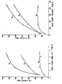
- Figure 2 shows lifetime to rupture, at 700°C and a stress of 36.6 ksi, as a function of boron content for three different levels of phosphorus content.
- Curve 30 shows that increasing boron content in alloys containing 0.005 wt.% phosphorus while initially producing a small increase in rupture lifetime, does not produce an increase in rupture lifetime above boron contents of 0.0028 wt.%.
- Curve 20, for alloys containing nominally 0.03 wt.% phosphorus indicates that increasing the boron content of these alloys results in a substantially linear increase in the rupture life time.
- Curve 10 for alloys containing nominally 0.085 wt.% phosphorus indicates that increasing the boron content from 0.0008 wt.% to 0.0029 wt.% results in an approximate tripling of the stress rupture life time. Increasing the boron content from 0.0029 to 0.0064 wt.% results in a further increase in rupture lifetime which is, however, not as large as the increase in going from 0.0008 to 0.0029 wt.%.
- Figure 3 utilizing the same data used to plot the Figure 2 curves, shows the stress rupture lifetime as a function of phosphorus content for three different levels of boron content.
- Curve 60 for alloys containing nominally 0.0008 wt.% boron, shows that increasing phosphorus from less than 0.005 wt.% to about 0.03 wt.% produces a small increase in rupture lifetime, but that further increases in phosphorus content do not produce further increases in rupture lifetime.
- Curve 50 for alloys containing about 0.003 wt.% boron, shows that increasing phosphorus produces an almost linearly increasing stress rupture lifetime from just above 100 hours for less than 0.005 wt.% phosphorus to over 500 hours for about 0.085 wt.% phosphorus.
- Curve 40 for alloys containing about 0.006 wt.% boron, shows that up to about 0.03 wt.% phosphorus, rupture lifetime increases at a faster rate than in the 0.003 wt.% boron alloys 50, but beyond about .030 wt.% phosphorus, the rate of increase in rupture lifetime with phosphorus content is substantially the same as that shown by curve 50 for the same phosphorus content interval.
- boron should be present at levels of 0.003 wt.% to 0.006 wt.%, and phosphorus should be present between 0.025 wt.% and 0.06 wt.%.
- Maximum stress rupture lifetime can be obtained by simultaneously maximizing the boron and phosphorus contents within the above ranges.
- Approximately equivalent stress rupture lifetimes can be maintained between different alloys having varying boron and phosphorus contents within the aforementioned ranges by setting the product of the phosphorus and boron contents of the desired alloy equal to the product of the phosphorus and boron contents of the other alloy.
Abstract
Description
- This invention relates to austenitic stainless steel alloys for use in high temperature applications, especially nuclear reactor applications.
- United States Patent Application Serial No. 414,167 (Bates et al), filed on September 2, 1982, pertains to austenitic stainless steels containing increased levels of phosphorus to provide enhanced in-reactor swelling resistance.
- One of the prime objectives in the efforts to develop a commerically viable liquid metal fast breeder reactor (LMFBR) has been to develop an alloy, or alloys, which are swelling resistant and have the required in-reactor mechanical properties for use as fuel cladding and/or use as ducts. The fuel cladding will see service in contact with flowing liquid sodium and have a surface temperature of about 400°C (-750°F) to 650°C (~1200°F). A duct surrounds each bundle of fuel pins and sees service at about 380°C (-715°F) to 550°C (-1020°F). These components will be exposed at the aforementioned elevated temperatures to fast neutron fluxes on the order of 1015 n/cm 2 . S (E 0.1 MeV), and should be capable of performing adequately to fluences on the order of 2 to 3 X 10²³ n/cm 2 (E>0.1 MeV).
- Initially, one of the prime candidate alloys for commercial LMFBR, fuel cladding and ducts was 20% cold worked AISI 316 steel, a solid solution strengthened austenitic stainless steel (see Bennett and Horton, "Material Requirements for Liquid Metal Fast Breeder Reactor," Metallurgical Transactions A, Vol. 9A, February 1978, pp. 143-149). Typical chemistry and material fabrication steps for nuclear grade 316 fuel cladding are described in copending United States Patent Application Serial No. 359,549 filed on March 18, 1982.
- Current commercial composition specifications for nuclear grade 316 stainless steel contain only a maximum value for impurities such as phosphorus, sulphur, boron, aluminum, niobium, vanadium, tantalum, copper and cobalt. Typical commercial melting procedure for this alloy involves double-vacuum melting of electrolytic-grade starting materials. This practice results in low levels of the aforementioned impurities, which depending on the particular impurity, may be 10 to 100 times less than the maximum value allowed by the specification.
- However, the 316 alloy undergoes a high degree of void swelling during extended exposure to fast neutron fluxes at the LMFBR operating temperatures. Extensive development efforts aimed at reducing swelling have been undertaken, and are exemplified by U.S. Patent No. 4,158,606 and copending United States Patent Application Serial No. 346,340 filed February 5, 1982 which is a continuation of an application filed on January 9, 1980.
- While the aforementioned efforts have led to improvements in swelling resistance, the stress rupture behavior of these alloys in fuel pin cladding applications remains as one of the major limitations on fuel pin life and improvements in this area are needed for long-life LMFBR cores.
- Accordingly the present invention resides in an austenitic stainless steel alloy characterized in that said alloy consists essentially of: 0.02 to 0.08 wt.% carbon; from 1.5 to 2.5 wt.% manganese; from 0.5 to 1.0 wt.% silicon; from 0.02 to 0.08 wt.% phosphorus; from 0.004 to 0.010 wt.% sulphur; from 12.5 to 14.5 wt.% chromium; from 14.5 to 16.5 wt.% nickel; from 1.5 to 2.5 wt.% molybdenum; from 0.02 to 0.05 wt.% aluminum; from 0.002 to 0.008 wt.% boron; from 0.1 to 0.4 wt.% titanium; up to 0.01 wt.% zirconium; from 0.02 to 0.05 wt.% niobium; from 0.01 to 0.05 wt.% vanadium; from 0.005 to 0.02 wt.% tantalum; from 0.01 to 0.04 wt.% copper; up to 0.01 wt.% nitrogen; up to 0.01 wt.% oxygen; from 0.02 to 0.05 wt.% cobalt; up to 0.03 wt.% arsenic; the balance being essentially iron with impurities; and in that the sum of the wt.% phosphorus plus the wt.% sulphur plus the wt.% boron is greater than 0.03 wt.%; and the ratio of the wt.% Ti to the sum of the wt.% carbon plus the wt.% nitrogen is between 4 and 6.
- Thus, it has now been discovered that in the solid solution strengthened austenitic stainless steels, stress rupture strength increases as the sum of the phosphorus, sulphur and boron contents of the alloy increase. Based on this discovery, alloy compositions have been developed having enhanced stress rupture properties and good swelling resistance, making them suitable for use as fuel pin cladding. These alloy compositions are summarized in Table I and utilize phosphorus, boron and sulphur, in conjunction with controlled quantities of selected impurities and a controlled ratio of wt.% titanium to the sum of the wt.% carbon and nitrogen, to provide the desired stress rupture properties.

- In accordance with the present invention, it is preferred that within the broad range shown in Table I that the sulphur content be limited to 0.005 to 0.010 wt.%, the phosphorus content be limited to 0.025 to 0.06 wt.%, and the boron content be limited to 0.003 to 0.006 wt.%.
- It is also preferred that the Ti/C+N for both the broad and preferred compositions shown in Table I be between 4. 5 and 5.5.
- While the alloys according to the present invention may be put to good use in any high temperature applications requiring good stress rupture properties in the temperature range of from 500 to 800°C, the present alloys are particularly well suited for use in elevated temperature, high fluence, fast neutron irradiation environments such as those encountered by fuel element cladding in an LMFBR core. In this application, the alloy requires a cold worked microstructure which may be produced by the final cold working step in tube fabrication. A 10 to 40%, and more preferably, a 15 to 25% final reduction in area is desired in the final cold working step.
- In order that the invention can be more clearly understood, convenient embodiments thereof will now be described, by way of example, with reference to the accompanying drawing in which:
- Figure 1 shows a graph of the stress required to produce rupture in 1000 hours at 650°C as a function of the sum of the phosphorus, boron and sulphur contents in weight percent;
- Figure 2 shows the effect of varying boron contents on stress rupture life at 700°C for a stress of 36.6 ksi for three different phosphorus contents;
- Figure 3 shows the effect of varying phosphorus contents on stress rupture life at 700°C for a stress of 36.6 ksi for three different boron contents; and
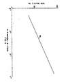
- Figure 4 shows stress rupture life at 700°C under an applied stress of 36.6 ksi as function the (wt.% P)X(wt.%B).
- As demonstrated in Figure 1, it has now been discovered that stress rupture strength in austenitic stainless steels is a function of the sum of the phosphorus, sulfur and boron contents of the alloy. More particularly, curve 1 shows that the stress required to produce rupture in these alloys in 1000 hours at 650°C increases substantially linearly with increasing phosphorus, sulphur and boron content.
- Based on the relationship between rupture strength and the aforementioned elements disclosed by Figure 1, it is required that the alloys of the present invention have at least 0.03 wt.%, and preferably at least 0.035 wt.%, total, of boron, phosphorus and sulphur. It is further believed that small, but finite amounts of the impurities niobium, vanadium, tantalum, aluminum, copper, and cobalt, should also be present to provide the desired stress rupture properties. To this end, minimum values have been set for each of these elements as shown by Table I.
- In addition, in the alloys of the present invention, it is required that the ratio (on a weight percentage basis) of titanium to the sum of carbon and nitrogen be between 4 and 6 and most preferably about 5. It is believed that in the present alloys, the aforementioned Ti/(C+N) ratio range is conducive to placing a large fraction of the carbon and nitrogen atoms in the alloy into fine, Ti(C,N) particles dispersed through the cold worked austenitic matrix. In alloys having the specified Ti/(C+N) ratios, these fine Ti(C,N) particles are expected to be more resistant to coarsening during elevated temperature use and thereby maintain the inhibiting effect these particles have on dislocation motion for longer periods of elevated temperature use at a specific temperature.
- In producing the alloys according to the present invention, the electrolytically pure starting materials of the prior art may be partially or entirely replaced by scrap which has been selected to provide a melt chemistry, meeting the requirements of Table I. Any of the melting techniques known in the art may be used in the production of the present alloys so long as they are capable of providing a product meeting the Table I chemistry requirements. Double-vacuum melting is specifically contemplated.
- Standard hot working, cold working and annealing techniques used in the prior art may be utilized to fabricate final size components from ingots of the present alloys. Fuel element cladding may be fabricated from hot worked billets by cold working reductions having anneals between each reduction as is described in the above- mentioned copending United States Patent Application Serial Nos. 414,167 and 359,549. The finished cladding should have a cold worked microstructure produced by a final cold working reduction of about 10 to 40% in cross- sectional area, with reductions of 15 to 25% being preferred.
- The invention will now be illustrated with reference to the following Example:
- Nine heats having the compositions shown in Table II, with varying boron and phosphorus contents, were melted and fabricated down to round bar stock having a diameter of about 0.53 to 0.532 inches. Prior to the final cold working reduction, the alloys were annealed at about 1066°C for about 15 minutes and then air-cooled. The final cold working reduction was about 23%.
- Stress rupture testing of the final cold worked bars, highlighted an unexpected and surprising interaction between boron and phosphorus contents shown in Figures 2 to 4. These Figures indicate that stress rupture lifetime is dependent on a strong interaction between the boron and phosphorus contents of these alloys.
- Figure 2 shows lifetime to rupture, at 700°C and a stress of 36.6 ksi, as a function of boron content for three different levels of phosphorus content.
Curve 30 shows that increasing boron content in alloys containing 0.005 wt.% phosphorus while initially producing a small increase in rupture lifetime, does not produce an increase in rupture lifetime above boron contents of 0.0028 wt.%.Curve 20, for alloys containing nominally 0.03 wt.% phosphorus, indicates that increasing the boron content of these alloys results in a substantially linear increase in the rupture life time.Curve 10 for alloys containing nominally 0.085 wt.% phosphorus, indicates that increasing the boron content from 0.0008 wt.% to 0.0029 wt.% results in an approximate tripling of the stress rupture life time. Increasing the boron content from 0.0029 to 0.0064 wt.% results in a further increase in rupture lifetime which is, however, not as large as the increase in going from 0.0008 to 0.0029 wt.%. - Figure 3, utilizing the same data used to plot the Figure 2 curves, shows the stress rupture lifetime as a function of phosphorus content for three different levels of boron content.
Curve 60, for alloys containing nominally 0.0008 wt.% boron, shows that increasing phosphorus from less than 0.005 wt.% to about 0.03 wt.% produces a small increase in rupture lifetime, but that further increases in phosphorus content do not produce further increases in rupture lifetime.Curve 50, for alloys containing about 0.003 wt.% boron, shows that increasing phosphorus produces an almost linearly increasing stress rupture lifetime from just above 100 hours for less than 0.005 wt.% phosphorus to over 500 hours for about 0.085 wt.% phosphorus.Curve 40, for alloys containing about 0.006 wt.% boron, shows that up to about 0.03 wt.% phosphorus, rupture lifetime increases at a faster rate than in the 0.003 wt.%boron alloys 50, but beyond about .030 wt.% phosphorus, the rate of increase in rupture lifetime with phosphorus content is substantially the same as that shown bycurve 50 for the same phosphorus content interval. -

- In Figure 4, the base ten logarithm of rupture lifetime is plotted as a function of the base ten logarithm of the product of the wt.% phosphorus times the wt.% boron.
Curve 100, based on the data used to generate Figures 2 and 3, shows that rupture lifetime is a function of the product of the phosphorus and boron content where:


- Based on the data shown in Figures 2 through 4, it is apparent that: (1) at boron contents of about 0.001 wt.% or less, increasing the phosphorus content from 0.005 to about 0.085 wt.% will not produce any significant change in rupture lifetime; and (2) at phosphorus contents less than 0.02 wt.%, that increasing the boron content will not produce any significant change in rupture lifetime. Therefore, it is believed that in the present alloys it is critical that there be at least 0.002 wt.% boron and 0.02 wt.% phosphorus present. The maximum boron and phosphorus contents should be maintained below about 0.008 wt.% and about 0.08 wt.%, respectively, to assure the fabricability and weldability of the alloys. To achieve an optimum combination of rupture, fabrication and welding properties, boron should be present at levels of 0.003 wt.% to 0.006 wt.%, and phosphorus should be present between 0.025 wt.% and 0.06 wt.%. Maximum stress rupture lifetime can be obtained by simultaneously maximizing the boron and phosphorus contents within the above ranges. Approximately equivalent stress rupture lifetimes can be maintained between different alloys having varying boron and phosphorus contents within the aforementioned ranges by setting the product of the phosphorus and boron contents of the desired alloy equal to the product of the phosphorus and boron contents of the other alloy.
Claims (9)
Applications Claiming Priority (2)
| Application Number | Priority Date | Filing Date | Title |
|---|---|---|---|
| US06/484,322 US4530719A (en) | 1983-04-12 | 1983-04-12 | Austenitic stainless steel for high temperature applications |
| US484322 | 2000-01-18 |
Publications (3)
| Publication Number | Publication Date |
|---|---|
| EP0121630A2 true EP0121630A2 (en) | 1984-10-17 |
| EP0121630A3 EP0121630A3 (en) | 1985-01-09 |
| EP0121630B1 EP0121630B1 (en) | 1987-07-29 |
Family
ID=23923668
Family Applications (1)
| Application Number | Title | Priority Date | Filing Date |
|---|---|---|---|
| EP83307474A Expired EP0121630B1 (en) | 1983-04-12 | 1983-12-08 | Improved austenitic stainless steel alloys for high temperature applications |
Country Status (6)
| Country | Link |
|---|---|
| US (1) | US4530719A (en) |
| EP (1) | EP0121630B1 (en) |
| JP (1) | JPS59190351A (en) |
| CA (1) | CA1217359A (en) |
| DE (1) | DE3372791D1 (en) |
| ES (1) | ES8801708A1 (en) |
Cited By (3)
| Publication number | Priority date | Publication date | Assignee | Title |
|---|---|---|---|---|
| EP0371202A1 (en) * | 1988-11-30 | 1990-06-06 | Westinghouse Electric Corporation | High strength martensitic steel alloy and method of preparing same |
| EP0530725A1 (en) * | 1991-09-03 | 1993-03-10 | Hitachi, Ltd. | Austenitic stainless steel having superior resistance to irradiation-induced segregation |
| CN113493881A (en) * | 2021-06-24 | 2021-10-12 | 江苏良工精密合金钢有限公司 | Super-pure heat-resistant stainless steel bar and manufacturing process thereof |
Families Citing this family (6)
| Publication number | Priority date | Publication date | Assignee | Title |
|---|---|---|---|---|
| US4613479A (en) * | 1984-03-14 | 1986-09-23 | Westinghouse Electric Corp. | Water reactor fuel cladding |
| US4863682A (en) * | 1988-03-11 | 1989-09-05 | General Electric Company | Austenitic stainless steel alloy |
| US5196272A (en) * | 1989-08-01 | 1993-03-23 | Ishikawajima-Harima Heavy Industries Co., Ltd. | Corrosion resistant stainless steel |
| US5475723A (en) * | 1994-03-21 | 1995-12-12 | General Electric Company | Nuclear fuel cladding with hydrogen absorbing inner liner |
| JP5861599B2 (en) * | 2012-09-04 | 2016-02-16 | 新日鐵住金株式会社 | Austenitic stainless steel for nuclear reactors |
| CN110951955A (en) * | 2019-11-11 | 2020-04-03 | 邯郸钢铁集团有限责任公司 | Low-cost high-strength steel Q460MD for engineering machinery and production method thereof |
Citations (7)
| Publication number | Priority date | Publication date | Assignee | Title |
|---|---|---|---|---|
| US3118761A (en) * | 1955-05-09 | 1964-01-21 | Westinghouse Electric Corp | Crack resistant austenitic stainless steel alloys |
| DE1558635B2 (en) * | 1966-02-10 | 1970-06-18 | Sumitomo Kinzoku Kogyo Kabushiki Kaisha, Osaka (Japan) | High-strength, stable austenitic corrosion-resistant steel for the production of evaporator tubes and superheater tubes |
| GB1361055A (en) * | 1970-07-14 | 1974-07-24 | Sumitomo Metal Ind | Ioron-nickel-chromium alloys |
| US4158606A (en) * | 1977-01-27 | 1979-06-19 | The United States Department Of Energy | Austenitic stainless steel alloys having improved resistance to fast neutron-induced swelling |
| GB2036077A (en) * | 1977-10-12 | 1980-06-25 | Nippon Stainless Steel Co | High temperature oxidization proof austenitic steel |
| EP0037446A1 (en) * | 1980-01-09 | 1981-10-14 | Westinghouse Electric Corporation | Austenitic iron base alloy |
| EP0106426A1 (en) * | 1982-09-02 | 1984-04-25 | Westinghouse Electric Corporation | Austenitic alloys and reactor components made thereof |
Family Cites Families (4)
| Publication number | Priority date | Publication date | Assignee | Title |
|---|---|---|---|---|
| JPS53131397A (en) * | 1977-04-22 | 1978-11-16 | Toshiba Corp | Nuclear fuel element |
| US4407673A (en) * | 1980-01-09 | 1983-10-04 | Korenko Michael K | Solid solution strengthened duct and cladding alloy D9-B1 |
| JPS5856024B2 (en) * | 1980-03-08 | 1983-12-13 | 動力炉・核燃料開発事業団 | Austenitic steel for fast reactor core structure |
| US4421572A (en) * | 1982-03-18 | 1983-12-20 | The United States Of America As Represented By The United States Department Of Energy | Thermomechanical treatment of alloys |
-
1983
- 1983-04-12 US US06/484,322 patent/US4530719A/en not_active Expired - Fee Related
- 1983-12-08 DE DE8383307474T patent/DE3372791D1/en not_active Expired
- 1983-12-08 EP EP83307474A patent/EP0121630B1/en not_active Expired
- 1983-12-09 ES ES527922A patent/ES8801708A1/en not_active Expired
- 1983-12-09 JP JP58233469A patent/JPS59190351A/en active Pending
- 1983-12-09 CA CA000442973A patent/CA1217359A/en not_active Expired
Patent Citations (7)
| Publication number | Priority date | Publication date | Assignee | Title |
|---|---|---|---|---|
| US3118761A (en) * | 1955-05-09 | 1964-01-21 | Westinghouse Electric Corp | Crack resistant austenitic stainless steel alloys |
| DE1558635B2 (en) * | 1966-02-10 | 1970-06-18 | Sumitomo Kinzoku Kogyo Kabushiki Kaisha, Osaka (Japan) | High-strength, stable austenitic corrosion-resistant steel for the production of evaporator tubes and superheater tubes |
| GB1361055A (en) * | 1970-07-14 | 1974-07-24 | Sumitomo Metal Ind | Ioron-nickel-chromium alloys |
| US4158606A (en) * | 1977-01-27 | 1979-06-19 | The United States Department Of Energy | Austenitic stainless steel alloys having improved resistance to fast neutron-induced swelling |
| GB2036077A (en) * | 1977-10-12 | 1980-06-25 | Nippon Stainless Steel Co | High temperature oxidization proof austenitic steel |
| EP0037446A1 (en) * | 1980-01-09 | 1981-10-14 | Westinghouse Electric Corporation | Austenitic iron base alloy |
| EP0106426A1 (en) * | 1982-09-02 | 1984-04-25 | Westinghouse Electric Corporation | Austenitic alloys and reactor components made thereof |
Cited By (4)
| Publication number | Priority date | Publication date | Assignee | Title |
|---|---|---|---|---|
| EP0371202A1 (en) * | 1988-11-30 | 1990-06-06 | Westinghouse Electric Corporation | High strength martensitic steel alloy and method of preparing same |
| EP0530725A1 (en) * | 1991-09-03 | 1993-03-10 | Hitachi, Ltd. | Austenitic stainless steel having superior resistance to irradiation-induced segregation |
| US5316597A (en) * | 1991-09-03 | 1994-05-31 | Hitachi, Ltd. | A nuclear reactor comprising a reactor vessel and structural members made of an austenitic stainless steel having superior resistance to irradiation-induced segregation |
| CN113493881A (en) * | 2021-06-24 | 2021-10-12 | 江苏良工精密合金钢有限公司 | Super-pure heat-resistant stainless steel bar and manufacturing process thereof |
Also Published As
| Publication number | Publication date |
|---|---|
| US4530719A (en) | 1985-07-23 |
| EP0121630B1 (en) | 1987-07-29 |
| ES527922A0 (en) | 1988-02-16 |
| DE3372791D1 (en) | 1987-09-03 |
| EP0121630A3 (en) | 1985-01-09 |
| CA1217359A (en) | 1987-02-03 |
| ES8801708A1 (en) | 1988-02-16 |
| JPS59190351A (en) | 1984-10-29 |
Similar Documents
| Publication | Publication Date | Title |
|---|---|---|
| US4212686A (en) | Zirconium alloys | |
| JP2914457B2 (en) | ZIRLO type material | |
| CA1066922A (en) | Heat-resistant allow for welded structures | |
| EP2647732A1 (en) | Precipitation-strengthened ni-based heat-resistant alloy and method for producing the same | |
| ZA200509729B (en) | Zirconium alloy and components for the core of light water cooled nuclear reactors | |
| US4049431A (en) | High strength ferritic alloy | |
| EP0121630B1 (en) | Improved austenitic stainless steel alloys for high temperature applications | |
| US4844864A (en) | Precipitation hardenable, nickel-base alloy | |
| EP0106426B1 (en) | Austenitic alloys and reactor components made thereof | |
| US4818485A (en) | Radiation resistant austenitic stainless steel alloys | |
| US4231795A (en) | High weldability nickel-base superalloy | |
| US4040876A (en) | High temperature alloys and members thereof | |
| EP0174418B1 (en) | Austenitic alloys based on iron-manganese and iron-manganese-chromium | |
| US4385933A (en) | Highly heat resistant austenitic iron-nickel-chromium alloys which are resistant to neutron induced swelling and corrosion by liquid sodium | |
| US4842814A (en) | Nuclear reactor fuel assembly | |
| EP0076110B1 (en) | Maraging superalloys and heat treatment processes | |
| US4144059A (en) | Ductile long range ordered alloys with high critical ordering temperature and wrought articles fabricated therefrom | |
| EP0037446B1 (en) | Austenitic iron base alloy | |
| US3856517A (en) | Irradiation swelling resistant alloy for use in fast neutron reactors | |
| US3597193A (en) | Vanadium base alloy | |
| US4299625A (en) | Niobium-base alloy | |
| JP2000282101A (en) | Manufacture of oxide dispersion-strengthened ferritic steel | |
| Iwao et al. | Mechanical properties of vanadium-base binary alloys | |
| CN112981273A (en) | Ferritic alloy and method for manufacturing nuclear fuel cladding tube using the same | |
| US3695866A (en) | Vanadium-base alloy having a high creep-rupture strength and an improved resistance to corrosion |
Legal Events
| Date | Code | Title | Description |
|---|---|---|---|
| PUAI | Public reference made under article 153(3) epc to a published international application that has entered the european phase |
Free format text: ORIGINAL CODE: 0009012 |
|
| AK | Designated contracting states |
Designated state(s): BE DE FR GB IT NL SE |
|
| PUAL | Search report despatched |
Free format text: ORIGINAL CODE: 0009013 |
|
| AK | Designated contracting states |
Designated state(s): BE DE FR GB IT NL SE |
|
| 17P | Request for examination filed |
Effective date: 19850704 |
|
| 17Q | First examination report despatched |
Effective date: 19860221 |
|
| GRAA | (expected) grant |
Free format text: ORIGINAL CODE: 0009210 |
|
| AK | Designated contracting states |
Kind code of ref document: B1 Designated state(s): BE DE FR GB IT NL SE |
|
| REF | Corresponds to: |
Ref document number: 3372791 Country of ref document: DE Date of ref document: 19870903 |
|
| ET | Fr: translation filed | ||
| ITF | It: translation for a ep patent filed |
Owner name: MODIANO & ASSOCIATI S.R.L. |
|
| PGFP | Annual fee paid to national office [announced via postgrant information from national office to epo] |
Ref country code: NL Payment date: 19871231 Year of fee payment: 5 |
|
| PLBI | Opposition filed |
Free format text: ORIGINAL CODE: 0009260 |
|
| 26 | Opposition filed |
Opponent name: COMMISSARIAT A L'ENERGIE ATOMIQUE Effective date: 19880418 |
|
| NLR1 | Nl: opposition has been filed with the epo |
Opponent name: COMMISSARIAT A L'ENERGIE ATOMIQUE |
|
| PGFP | Annual fee paid to national office [announced via postgrant information from national office to epo] |
Ref country code: DE Payment date: 19881227 Year of fee payment: 6 |
|
| ITTA | It: last paid annual fee | ||
| PG25 | Lapsed in a contracting state [announced via postgrant information from national office to epo] |
Ref country code: GB Effective date: 19891208 |
|
| PG25 | Lapsed in a contracting state [announced via postgrant information from national office to epo] |
Ref country code: SE Effective date: 19891209 |
|
| PG25 | Lapsed in a contracting state [announced via postgrant information from national office to epo] |
Ref country code: BE Effective date: 19891231 |
|
| BERE | Be: lapsed |
Owner name: WESTINGHOUSE ELECTRIC CORP. Effective date: 19891231 |
|
| PG25 | Lapsed in a contracting state [announced via postgrant information from national office to epo] |
Ref country code: NL Effective date: 19900701 |
|
| GBPC | Gb: european patent ceased through non-payment of renewal fee | ||
| NLV4 | Nl: lapsed or anulled due to non-payment of the annual fee | ||
| PG25 | Lapsed in a contracting state [announced via postgrant information from national office to epo] |
Ref country code: FR Effective date: 19900831 |
|
| PG25 | Lapsed in a contracting state [announced via postgrant information from national office to epo] |
Ref country code: DE Effective date: 19900901 |
|
| PLBN | Opposition rejected |
Free format text: ORIGINAL CODE: 0009273 |
|
| STAA | Information on the status of an ep patent application or granted ep patent |
Free format text: STATUS: OPPOSITION REJECTED |
|
| REG | Reference to a national code |
Ref country code: FR Ref legal event code: ST |
|
| 27O | Opposition rejected |
Effective date: 19900630 |
|
| EUG | Se: european patent has lapsed |
Ref document number: 83307474.3 Effective date: 19900830 |