EP0121392A2 - Methode und Vorrichtungen für Spitzenleistung oder für Spitzenleistungverminderung - Google Patents
Methode und Vorrichtungen für Spitzenleistung oder für Spitzenleistungverminderung Download PDFInfo
- Publication number
- EP0121392A2 EP0121392A2 EP84302022A EP84302022A EP0121392A2 EP 0121392 A2 EP0121392 A2 EP 0121392A2 EP 84302022 A EP84302022 A EP 84302022A EP 84302022 A EP84302022 A EP 84302022A EP 0121392 A2 EP0121392 A2 EP 0121392A2
- Authority
- EP
- European Patent Office
- Prior art keywords
- power plant
- generator
- turbine
- prime mover
- internal combustion
- Prior art date
- Legal status (The legal status is an assumption and is not a legal conclusion. Google has not performed a legal analysis and makes no representation as to the accuracy of the status listed.)
- Ceased
Links
Images
Classifications
-
- F—MECHANICAL ENGINEERING; LIGHTING; HEATING; WEAPONS; BLASTING
- F01—MACHINES OR ENGINES IN GENERAL; ENGINE PLANTS IN GENERAL; STEAM ENGINES
- F01K—STEAM ENGINE PLANTS; STEAM ACCUMULATORS; ENGINE PLANTS NOT OTHERWISE PROVIDED FOR; ENGINES USING SPECIAL WORKING FLUIDS OR CYCLES
- F01K23/00—Plants characterised by more than one engine delivering power external to the plant, the engines being driven by different fluids
- F01K23/12—Plants characterised by more than one engine delivering power external to the plant, the engines being driven by different fluids the engines being mechanically coupled
- F01K23/14—Plants characterised by more than one engine delivering power external to the plant, the engines being driven by different fluids the engines being mechanically coupled including at least one combustion engine
-
- F—MECHANICAL ENGINEERING; LIGHTING; HEATING; WEAPONS; BLASTING
- F01—MACHINES OR ENGINES IN GENERAL; ENGINE PLANTS IN GENERAL; STEAM ENGINES
- F01K—STEAM ENGINE PLANTS; STEAM ACCUMULATORS; ENGINE PLANTS NOT OTHERWISE PROVIDED FOR; ENGINES USING SPECIAL WORKING FLUIDS OR CYCLES
- F01K25/00—Plants or engines characterised by use of special working fluids, not otherwise provided for; Plants operating in closed cycles and not otherwise provided for
- F01K25/08—Plants or engines characterised by use of special working fluids, not otherwise provided for; Plants operating in closed cycles and not otherwise provided for using special vapours
-
- F—MECHANICAL ENGINEERING; LIGHTING; HEATING; WEAPONS; BLASTING
- F02—COMBUSTION ENGINES; HOT-GAS OR COMBUSTION-PRODUCT ENGINE PLANTS
- F02B—INTERNAL-COMBUSTION PISTON ENGINES; COMBUSTION ENGINES IN GENERAL
- F02B1/00—Engines characterised by fuel-air mixture compression
- F02B1/02—Engines characterised by fuel-air mixture compression with positive ignition
- F02B1/04—Engines characterised by fuel-air mixture compression with positive ignition with fuel-air mixture admission into cylinder
-
- Y—GENERAL TAGGING OF NEW TECHNOLOGICAL DEVELOPMENTS; GENERAL TAGGING OF CROSS-SECTIONAL TECHNOLOGIES SPANNING OVER SEVERAL SECTIONS OF THE IPC; TECHNICAL SUBJECTS COVERED BY FORMER USPC CROSS-REFERENCE ART COLLECTIONS [XRACs] AND DIGESTS
- Y02—TECHNOLOGIES OR APPLICATIONS FOR MITIGATION OR ADAPTATION AGAINST CLIMATE CHANGE
- Y02E—REDUCTION OF GREENHOUSE GAS [GHG] EMISSIONS, RELATED TO ENERGY GENERATION, TRANSMISSION OR DISTRIBUTION
- Y02E20/00—Combustion technologies with mitigation potential
- Y02E20/14—Combined heat and power generation [CHP]
-
- Y—GENERAL TAGGING OF NEW TECHNOLOGICAL DEVELOPMENTS; GENERAL TAGGING OF CROSS-SECTIONAL TECHNOLOGIES SPANNING OVER SEVERAL SECTIONS OF THE IPC; TECHNICAL SUBJECTS COVERED BY FORMER USPC CROSS-REFERENCE ART COLLECTIONS [XRACs] AND DIGESTS
- Y02—TECHNOLOGIES OR APPLICATIONS FOR MITIGATION OR ADAPTATION AGAINST CLIMATE CHANGE
- Y02T—CLIMATE CHANGE MITIGATION TECHNOLOGIES RELATED TO TRANSPORTATION
- Y02T10/00—Road transport of goods or passengers
- Y02T10/10—Internal combustion engine [ICE] based vehicles
- Y02T10/12—Improving ICE efficiencies
Definitions
- This invention relates to a method and means for peaking or peak power shaving.
- a utility builds and regularly operates its most efficient plant to supply the base load of the customers connected to its grid and supplies intermediate loads, greater than the base load, from less efficient plants.
- Peak power is supplied by operating diesel or gas turbine generating plants for very short intervals of time. These peak power generating units can quickly be brought onto and removed from the line and are advantageous from this standpoint. However, they are relatively inefficient and hence more expensive to operate than either the base or intermediate load power plants, such as coal or oil burning plants. Consequently, the cost of peak power is several times that of what is termed base load power.
- the load requirements are so high, and the actual equipment to supply such load so complex and costly that the plant is charged a fixed annual premium in order for the utility to be able to guarantee that it can deliver to the plant either 100% of its installed load, or predetermined portion thereof reached by agreement.
- the electrical bill of a large industrial plant has two components: a variable charge based on actual energy consumed, and a fixed annual charge based on the installed electrical capacity of the plant or the 'peak power which the utility is obligated to furnish on demand to the plant.
- the fixed annual charge may be as high as $100 per kw.
- a plant may install a standby power generating system based on a diesel driven generator whose operation is assured when the power being supplied by utility reaches the level predetermined by agreement between the utility and the plant.
- the switching in of standby generating capacity for supplying "peak power shaving” is cost effective after the fixed change reaches a threshold.
- Computerized power saving techniques a.re presently in use for continuously monitoring the connected electrical load of a plant. These techniques arrange for hierarchical shut down of the plant as the connected load increases beyond the total committed by the utility; for example, lighting loads are usually shed first. Thus, the peak power requirement of an industrial plant is of considerable economic importance 'in planning the operation of the plant.
- a selectively operable coupling connects the output of the prime mover to the generator so that on demand, the prime mover can drive the generator providing peak power shaving in the amount of the capacity of the prime mover.
- the generating capacity of the generator is selected as the sum of the individual capacities of the turbine and prime mover. This arrangement is cost effective because the incremental cost is oversizing the generator relative to the Ranking cycle turbine is relatively small, and the prime mover provides the desired reliability for the peak power shaving operation. Because the output of the generator is sold back to the utility at a premium price, the net cost to increase the capacity of the generator and install the prime mover is about the same as the net income which derives from the sale of its power derived from the gross income from the sale of its power less the cost of fuel. When the prime mover is a.n internal combustion engine, the system will pay for itself within one year.
- This serial, hybrid power generation system ma.kes waste heat utilization systems economically more attractive because the total saving is derived from the price of direct energy produced by the power plant as well as from a reduction in the annual fixed charge imposed on the industrial plant by the utility, such reduction being the capacity of the prime mover.
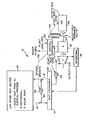
- this heat source can be waste heat from an industrial process, heat from a geothermal source, or heat from a solar pond such as is disclosed in U.S.A. patent application Serial 134,6.58, filed March 27, 1980.
- the power plant 10 comprises a heat exchanger 14 coupled by input lines 16 and output lines 18 to the heat source 12.
- the power plant includes a Rankine cycle turbine 24 which utilizes an organic working fluid such as Freon.
- a suitable turbine of this type is manufactured by Ormat Turbines Ltd. and is described in U.S.A. Patent 3,409,782.
- Organic working fluid in liquid form contained in the heat exchanger 14 is vaporized by heat from the source 12 when the by-pass valve 22 is in a closed state.
- the vaporized working fluid passes through a control valve 26 into the turbine 24 where the working fluid expands, causing the turbine to rotate and drive a generator 28.
- the electrical power produced by the generator is applied to the control circuit 30 which is arranged to supply the power to the electrical grid of the local utility when a co-generation arrangement has been reached with the power company.
- a quick-starting prime mover such as a gas turbine, or an internal combustion engine 36 such as a gasoline engine or a gas engine, but preferably a diesel engine.
- the generator 28 receives a part of its input from the internal combustion engine and a part from the turbine 24 if the by-pass valve 20 is closed.
- the generator 28 is oversized as compared with the capacities of the turbine 24 and the internal combustion engine 36.
- the capacity of the turbine 24 could be 500 kw and the capacity of the internal combustion engine could also be 500 kw; and in such case, the capacity of the generator would be 1000 kw to permit a simultaneous operation by both the turbine and the internal combustion engine.
- the control circuit 30 ha.s a control line 38 by which the by-pass valve 20 is operated, thereby providing either by-pass or operating conditions for the turbine.
- the control circuit 30 also has a control line 40 for controlling the valve 26 in the input vapour line to the turbine 24.
- the control line 42 of the circuit 30 selectively engages or disengages the coupling 34 for starting, stopping and running the internal combustion engine.
- control circuit 30 In normal operation, wherein the turbine would be operational and the internal combustion engine would not be operational, heat from a low grade heat source is converted into electrical energy by the turbine 24.
- the control circuit 30 maintains the by-pass valve 22 in its closed state and the valve 26 in its open state in order to permit the turbine 24 to operate.
- the generator 28 thus produces about 500 kw of electrical power which is supplied through the control circuit 30 to the local utility.
- the control circuit 30 is effective to maintain the coupling 34 disengaged and the internal combustion engine 36 in its "stop" condition.
- the control circuit 30 monitors the size of the plant load, and when this load reaches a predetermined limit established by agreement between the utility and the plant, the control circuit 30 responds by sending a "start" and “run” signal to the internal combustion engine 36, and an "engage” signal to the coupling 34 so that the output of the engine is also applied to the generator 28.
- This condition during which the internal combustion engine 36 contribute to the electrical generating capacity, will continue until the demand for a peak power has decreased to a threshold determined by the control circuit 30. At that time, the coupling 34 would disengage and a signal would be sent to the internal combustion engine for stopping it.
- a coupling 34 has been described but in actual practice a clutched gearbox or torque converter is preferred in order to permit start-up of the engine under no load conditions and the gradual coupling of this engine to the load.
- Various modes of operation are contemplated by which the inertia of the generator can be used to start the engine.
- the coupling 34 must be capable of permitting start-up of the prime mover whether the turbine is driving the generator or not.
- the present invention also envisages heat recovery from the exhaust gases of the prime mover.
- the control circuit 30 exerts its controlling function on the internal combustion engine 36 independently of whether the by-pass valve 20 is open or closed. Thus, the operator of the industrial process could shut down operation of turbine 24 in orderto maintain the heat exchanger 14 or because of other reasons associated with the heat source 12. In such case, the control circuit 30 would still be effective to place on-line the power generated by the internal combustion engine 36 upon demand for peak power as sensed by the control circuit 30.
- the cost of oversizing the generator 28 and providing the internal combustion engine 36 is about $100 per installed kw.
- the internal combustion engine will have to operate about 1500 hrs/year in order to provide peaking power.
- the electrical energy produced by the internal combustion engine will be purchased by the utility at a prmium rate, typically $0.10/kwh.
- the operator of the plant would receive about $150 per installed kw of internal combustion engine from the power company.
- fuel cost for running a diesel engine for 1500 hours per year is currently about $50/kw.
- the installed cost of the engine and oversizing the generator would be repaid within about a year from the savings afforded by operation of the internal combustion engine for peak power shaving only.
- each standby kw represented by the capacity of the internal combustion engine will result in a reduction in the annual fixed charge applied against the industrial plant with which the power plant 10 is associated.
Landscapes
- Engineering & Computer Science (AREA)
- Chemical & Material Sciences (AREA)
- Combustion & Propulsion (AREA)
- Mechanical Engineering (AREA)
- General Engineering & Computer Science (AREA)
- Engine Equipment That Uses Special Cycles (AREA)
- Control Of Turbines (AREA)
Applications Claiming Priority (2)
| Application Number | Priority Date | Filing Date | Title |
|---|---|---|---|
| US06/479,008 US4590384A (en) | 1983-03-25 | 1983-03-25 | Method and means for peaking or peak power shaving |
| US479008 | 1983-03-25 |
Publications (2)
| Publication Number | Publication Date |
|---|---|
| EP0121392A2 true EP0121392A2 (de) | 1984-10-10 |
| EP0121392A3 EP0121392A3 (de) | 1985-11-27 |
Family
ID=23902274
Family Applications (1)
| Application Number | Title | Priority Date | Filing Date |
|---|---|---|---|
| EP84302022A Ceased EP0121392A3 (de) | 1983-03-25 | 1984-03-26 | Methode und Vorrichtungen für Spitzenleistung oder für Spitzenleistungverminderung |
Country Status (4)
| Country | Link |
|---|---|
| US (1) | US4590384A (de) |
| EP (1) | EP0121392A3 (de) |
| IL (1) | IL71331A (de) |
| MX (1) | MX155889A (de) |
Cited By (10)
| Publication number | Priority date | Publication date | Assignee | Title |
|---|---|---|---|---|
| US5461858A (en) * | 1994-04-04 | 1995-10-31 | Energy Conversation Partnership, Ltd. | Method of producing hydroelectric power |
| AU694235B2 (en) * | 1994-07-06 | 1998-07-16 | Lwt Instruments Inc. | Logging or measurement while tripping |
| US6880344B2 (en) | 2002-11-13 | 2005-04-19 | Utc Power, Llc | Combined rankine and vapor compression cycles |
| US6892522B2 (en) | 2002-11-13 | 2005-05-17 | Carrier Corporation | Combined rankine and vapor compression cycles |
| US6962056B2 (en) | 2002-11-13 | 2005-11-08 | Carrier Corporation | Combined rankine and vapor compression cycles |
| US7146813B2 (en) | 2002-11-13 | 2006-12-12 | Utc Power, Llc | Power generation with a centrifugal compressor |
| US7174716B2 (en) | 2002-11-13 | 2007-02-13 | Utc Power Llc | Organic rankine cycle waste heat applications |
| US7254949B2 (en) | 2002-11-13 | 2007-08-14 | Utc Power Corporation | Turbine with vaned nozzles |
| US7281379B2 (en) | 2002-11-13 | 2007-10-16 | Utc Power Corporation | Dual-use radial turbomachine |
| EP2304196A1 (de) * | 2008-05-02 | 2011-04-06 | United Technologies Corporation | Kombiniertes geothermisches und solarthermisches orc-system |
Families Citing this family (39)
| Publication number | Priority date | Publication date | Assignee | Title |
|---|---|---|---|---|
| US5160080A (en) * | 1990-10-01 | 1992-11-03 | General Electric Company | Gas turbine engine and method of operation for providing increased output shaft horsepower |
| US5442906A (en) * | 1992-11-30 | 1995-08-22 | Union Oil Company Of California | Combined geothermal and fossil fuel power plant |
| US6526754B1 (en) | 1998-11-10 | 2003-03-04 | Ormat Industries Ltd. | Combined cycle power plant |
| US20030213246A1 (en) * | 2002-05-15 | 2003-11-20 | Coll John Gordon | Process and device for controlling the thermal and electrical output of integrated micro combined heat and power generation systems |
| US6598397B2 (en) | 2001-08-10 | 2003-07-29 | Energetix Micropower Limited | Integrated micro combined heat and power system |
| US7353653B2 (en) * | 2002-05-22 | 2008-04-08 | Ormat Technologies, Inc. | Hybrid power system for continuous reliable power at locations including remote locations |
| US8061139B2 (en) * | 2002-05-22 | 2011-11-22 | Ormat Technologies, Inc. | Integrated engine generator rankine cycle power system |
| US6883328B2 (en) * | 2002-05-22 | 2005-04-26 | Ormat Technologies, Inc. | Hybrid power system for continuous reliable power at remote locations |
| US6986251B2 (en) * | 2003-06-17 | 2006-01-17 | Utc Power, Llc | Organic rankine cycle system for use with a reciprocating engine |
| US6989989B2 (en) * | 2003-06-17 | 2006-01-24 | Utc Power Llc | Power converter cooling |
| US7017357B2 (en) | 2003-11-18 | 2006-03-28 | Carrier Corporation | Emergency power generation system |
| US7013644B2 (en) * | 2003-11-18 | 2006-03-21 | Utc Power, Llc | Organic rankine cycle system with shared heat exchanger for use with a reciprocating engine |
| US7036315B2 (en) * | 2003-12-19 | 2006-05-02 | United Technologies Corporation | Apparatus and method for detecting low charge of working fluid in a waste heat recovery system |
| US20050171736A1 (en) * | 2004-02-02 | 2005-08-04 | United Technologies Corporation | Health monitoring and diagnostic/prognostic system for an ORC plant |
| US7100380B2 (en) * | 2004-02-03 | 2006-09-05 | United Technologies Corporation | Organic rankine cycle fluid |
| US7428816B2 (en) * | 2004-07-16 | 2008-09-30 | Honeywell International Inc. | Working fluids for thermal energy conversion of waste heat from fuel cells using Rankine cycle systems |
| US7665304B2 (en) | 2004-11-30 | 2010-02-23 | Carrier Corporation | Rankine cycle device having multiple turbo-generators |
| US20060112693A1 (en) * | 2004-11-30 | 2006-06-01 | Sundel Timothy N | Method and apparatus for power generation using waste heat |
| US20060114994A1 (en) * | 2004-12-01 | 2006-06-01 | Silverstein D Amnon | Noise reduction in a digital video |
| US8141360B1 (en) | 2005-10-18 | 2012-03-27 | Florida Turbine Technologies, Inc. | Hybrid gas turbine and internal combustion engine |
| WO2008082388A1 (en) * | 2006-12-28 | 2008-07-10 | Utc Power Corporation | A power split device for a combined heat and power (chp) system |
| US20090145104A1 (en) * | 2007-12-10 | 2009-06-11 | General Electric Company | Combined cycle power plant with reserves capability |
| US8327654B2 (en) * | 2008-03-17 | 2012-12-11 | Denso International America, Inc. | Condenser, radiator, and fan module with Rankine cycle fan |
| EP2278220B1 (de) * | 2009-06-24 | 2014-03-05 | Balcke-Dürr GmbH | Wärmetauscher zur Dampferzeugung für ein solarthermisches Kraftwerk |
| JP5449014B2 (ja) * | 2010-05-07 | 2014-03-19 | 本田技研工業株式会社 | 発動発電機の自動起動停止装置 |
| US20130255258A1 (en) * | 2012-04-02 | 2013-10-03 | Ronald Lee Loveday | Rankine Cycle System |
| JP6040727B2 (ja) * | 2012-11-21 | 2016-12-07 | 株式会社Ihi | 過給機 |
| JP5999652B2 (ja) * | 2013-03-28 | 2016-09-28 | サンデンホールディングス株式会社 | 排熱回収装置 |
| US10008857B2 (en) | 2016-03-10 | 2018-06-26 | General Electric Company | DFIG-based UPS systems and methods of control |
| US11421663B1 (en) | 2021-04-02 | 2022-08-23 | Ice Thermal Harvesting, Llc | Systems and methods for generation of electrical power in an organic Rankine cycle operation |
| US11592009B2 (en) | 2021-04-02 | 2023-02-28 | Ice Thermal Harvesting, Llc | Systems and methods for generation of electrical power at a drilling rig |
| US11293414B1 (en) | 2021-04-02 | 2022-04-05 | Ice Thermal Harvesting, Llc | Systems and methods for generation of electrical power in an organic rankine cycle operation |
| US11480074B1 (en) | 2021-04-02 | 2022-10-25 | Ice Thermal Harvesting, Llc | Systems and methods utilizing gas temperature as a power source |
| US20220316452A1 (en) | 2021-04-02 | 2022-10-06 | Ice Thermal Harvesting, Llc | Systems for generating geothermal power in an organic rankine cycle operation during hydrocarbon production based on working fluid temperature |
| US11486370B2 (en) | 2021-04-02 | 2022-11-01 | Ice Thermal Harvesting, Llc | Modular mobile heat generation unit for generation of geothermal power in organic Rankine cycle operations |
| US11644015B2 (en) | 2021-04-02 | 2023-05-09 | Ice Thermal Harvesting, Llc | Systems and methods for generation of electrical power at a drilling rig |
| US11493029B2 (en) | 2021-04-02 | 2022-11-08 | Ice Thermal Harvesting, Llc | Systems and methods for generation of electrical power at a drilling rig |
| US11326550B1 (en) | 2021-04-02 | 2022-05-10 | Ice Thermal Harvesting, Llc | Systems and methods utilizing gas temperature as a power source |
| CN114718677B (zh) * | 2022-04-21 | 2024-04-05 | 苏州西热节能环保技术有限公司 | 一种供热供气机组的深度调峰热电解耦系统 |
Citations (5)
| Publication number | Priority date | Publication date | Assignee | Title |
|---|---|---|---|---|
| FR1290002A (fr) * | 1961-05-25 | 1962-04-06 | Licentia Gmbh | Installation de turbo-machines |
| US3350876A (en) * | 1966-01-19 | 1967-11-07 | Roy W P Johnson | Internal combustion engine plant |
| GB1159090A (en) * | 1968-05-20 | 1969-07-23 | Warnowwerft Warnemuende Veb | Combined Propulsion Plant for Ships. |
| DE2544179A1 (de) * | 1974-12-20 | 1976-07-01 | Gen Electric | Integrierte elektrizitaetserzeugungs- und klimatisierungseinrichtung |
| FR2296295A1 (fr) * | 1974-12-23 | 1976-07-23 | Semt | Dispositif pour la production de puissance electrique a partir de l'energie recuperee sur les gaz d'echappement d'un moteur a combustion interne |
Family Cites Families (9)
| Publication number | Priority date | Publication date | Assignee | Title |
|---|---|---|---|---|
| GB659714A (en) * | 1948-11-06 | 1951-10-24 | Svenska Turbinfab Ab | Improvements in units comprising a gas turbine driving an electric generator |
| GB751184A (en) * | 1954-07-07 | 1956-06-27 | Allgaier Werke Gmbh | Process and device for driving a working machine by means of several natural power machines with varying outputs and/or speed of revolution, in particular wind power plant, water turbines or the like |
| GB1101859A (en) * | 1964-12-25 | 1968-01-31 | Bronicki Lucien | Power generating units |
| GB1491625A (en) * | 1974-03-18 | 1977-11-09 | Inoue Japax Res | Electric power generation |
| US3944837A (en) * | 1974-08-26 | 1976-03-16 | Savco, Inc. | System and method for generation and distribution of electrical and thermal energy and automatic control apparatus suitable for use therein |
| CA986727A (en) * | 1975-03-21 | 1976-04-06 | Ernst Eggmann | Hybrid motor unit with energy storage |
| DE2750894A1 (de) * | 1977-09-14 | 1979-03-15 | Elmapa Nv | Einrichtung zur erzeugung von waermeenergie und elektrischer energie |
| US4186312A (en) * | 1978-02-23 | 1980-01-29 | Dvorak Sidney T | AC Electrical power systems with alternate sources of power |
| US4433547A (en) * | 1982-07-30 | 1984-02-28 | Firey Joseph C | Torque leveller |
-
1983
- 1983-03-25 US US06/479,008 patent/US4590384A/en not_active Expired - Lifetime
-
1984
- 1984-03-20 MX MX200730A patent/MX155889A/es unknown
- 1984-03-25 IL IL71331A patent/IL71331A/xx not_active IP Right Cessation
- 1984-03-26 EP EP84302022A patent/EP0121392A3/de not_active Ceased
Patent Citations (5)
| Publication number | Priority date | Publication date | Assignee | Title |
|---|---|---|---|---|
| FR1290002A (fr) * | 1961-05-25 | 1962-04-06 | Licentia Gmbh | Installation de turbo-machines |
| US3350876A (en) * | 1966-01-19 | 1967-11-07 | Roy W P Johnson | Internal combustion engine plant |
| GB1159090A (en) * | 1968-05-20 | 1969-07-23 | Warnowwerft Warnemuende Veb | Combined Propulsion Plant for Ships. |
| DE2544179A1 (de) * | 1974-12-20 | 1976-07-01 | Gen Electric | Integrierte elektrizitaetserzeugungs- und klimatisierungseinrichtung |
| FR2296295A1 (fr) * | 1974-12-23 | 1976-07-23 | Semt | Dispositif pour la production de puissance electrique a partir de l'energie recuperee sur les gaz d'echappement d'un moteur a combustion interne |
Cited By (13)
| Publication number | Priority date | Publication date | Assignee | Title |
|---|---|---|---|---|
| US5461858A (en) * | 1994-04-04 | 1995-10-31 | Energy Conversation Partnership, Ltd. | Method of producing hydroelectric power |
| AU694235B2 (en) * | 1994-07-06 | 1998-07-16 | Lwt Instruments Inc. | Logging or measurement while tripping |
| US6880344B2 (en) | 2002-11-13 | 2005-04-19 | Utc Power, Llc | Combined rankine and vapor compression cycles |
| US6892522B2 (en) | 2002-11-13 | 2005-05-17 | Carrier Corporation | Combined rankine and vapor compression cycles |
| US6962056B2 (en) | 2002-11-13 | 2005-11-08 | Carrier Corporation | Combined rankine and vapor compression cycles |
| US7146813B2 (en) | 2002-11-13 | 2006-12-12 | Utc Power, Llc | Power generation with a centrifugal compressor |
| US7174716B2 (en) | 2002-11-13 | 2007-02-13 | Utc Power Llc | Organic rankine cycle waste heat applications |
| US7254949B2 (en) | 2002-11-13 | 2007-08-14 | Utc Power Corporation | Turbine with vaned nozzles |
| US7281379B2 (en) | 2002-11-13 | 2007-10-16 | Utc Power Corporation | Dual-use radial turbomachine |
| US7735324B2 (en) | 2002-11-13 | 2010-06-15 | Carrier Corporation | Power generation with a centrifugal compressor |
| EP2304196A1 (de) * | 2008-05-02 | 2011-04-06 | United Technologies Corporation | Kombiniertes geothermisches und solarthermisches orc-system |
| EP2304196A4 (de) * | 2008-05-02 | 2014-09-10 | United Technologies Corp | Kombiniertes geothermisches und solarthermisches orc-system |
| US9297367B2 (en) | 2008-05-02 | 2016-03-29 | United Technologies Corporation | Combined geothermal and solar thermal organic rankine cycle system |
Also Published As
| Publication number | Publication date |
|---|---|
| US4590384A (en) | 1986-05-20 |
| EP0121392A3 (de) | 1985-11-27 |
| IL71331A0 (en) | 1984-06-29 |
| IL71331A (en) | 1992-08-18 |
| MX155889A (es) | 1988-01-06 |
Similar Documents
| Publication | Publication Date | Title |
|---|---|---|
| US4590384A (en) | Method and means for peaking or peak power shaving | |
| US4441028A (en) | Apparatus and method for multiplying the output of a generating unit | |
| US4428190A (en) | Power plant utilizing multi-stage turbines | |
| EP1016775B1 (de) | Abhitzewiedergewinnung in einem organischen Energiewandler mittels einem Zwischenflüssigkeitskreislauf | |
| RU2376693C2 (ru) | Снижение себестоимости многовариантной выработки электроэнергии путем использования наиболее выгодного на данный момент варианта выработки | |
| US4733536A (en) | Integrated mechanical vapor recompression apparatus and process for the cogeneration of electric and water-based power having a recirculation control system for part-load capacity | |
| US8987931B2 (en) | Flexible energy balancing system | |
| US6378285B1 (en) | Method for rapid startup and increase in output of a gas turbine plant | |
| HU202958B (en) | Method for combined electric power and heat producing at power plants operating with boilers of heat utilization | |
| Arakelyan et al. | Investigation of Technical and Economic Viability of the 450-MW CCGT Unit’s Operation in the GTU Based CHP Mode | |
| Fenton | Survey of cyclic load capabilities of fossil-steam generating units | |
| Nyanda et al. | Viability Analysis of Ubungo II Gas Power Plant Efficiency Improvement Using Co-generation System | |
| EP0442756A1 (de) | Elektrizitätskraftwerksanlage | |
| JP2002242694A (ja) | エネルギー貯蔵型ガスタービン発電装置 | |
| Clark | Cogeneration—efficient energy source | |
| Thumann et al. | Cogeneration: Theory and Practice | |
| US11840943B2 (en) | Flexible integration of stored heat and electric resources (fisher) | |
| GB2078864A (en) | District heating by combined heat and power | |
| JPS6243044B2 (de) | ||
| GB2038951A (en) | Improvement in Systems for Regasifying Liquefied Natural Gas to be Used in a Thermal Power Plant | |
| Burdenkova et al. | Optimization of schemes and ways to expand the adjustment range for the power supply of combined heat and power plants | |
| Nakhamkin et al. | Compressed Air Energy Storage: Plant Integration, Turbomachinery Development | |
| JPS6394011A (ja) | 高温水貯留槽を有する蒸気発電プラント | |
| WO2024019723A1 (en) | Electrolysis energy recovery | |
| Hedman et al. | Combined heat and power (CHP) |
Legal Events
| Date | Code | Title | Description |
|---|---|---|---|
| PUAI | Public reference made under article 153(3) epc to a published international application that has entered the european phase |
Free format text: ORIGINAL CODE: 0009012 |
|
| AK | Designated contracting states |
Designated state(s): DE FR NL |
|
| 17P | Request for examination filed |
Effective date: 19850322 |
|
| PUAL | Search report despatched |
Free format text: ORIGINAL CODE: 0009013 |
|
| AK | Designated contracting states |
Designated state(s): DE FR NL |
|
| 17Q | First examination report despatched |
Effective date: 19870109 |
|
| STAA | Information on the status of an ep patent application or granted ep patent |
Free format text: STATUS: THE APPLICATION HAS BEEN REFUSED |
|
| 18R | Application refused |
Effective date: 19911021 |
|
| APAF | Appeal reference modified |
Free format text: ORIGINAL CODE: EPIDOSCREFNE |
|
| RIN1 | Information on inventor provided before grant (corrected) |
Inventor name: BRONICKI, LUCIEN YEHUDA |