EP0120594B1 - Electro-pneumatic transducer assemblies - Google Patents
Electro-pneumatic transducer assemblies Download PDFInfo
- Publication number
- EP0120594B1 EP0120594B1 EP84301086A EP84301086A EP0120594B1 EP 0120594 B1 EP0120594 B1 EP 0120594B1 EP 84301086 A EP84301086 A EP 84301086A EP 84301086 A EP84301086 A EP 84301086A EP 0120594 B1 EP0120594 B1 EP 0120594B1
- Authority
- EP
- European Patent Office
- Prior art keywords
- nozzle
- assembly
- transducer
- bellows
- backpressure
- Prior art date
- Legal status (The legal status is an assumption and is not a legal conclusion. Google has not performed a legal analysis and makes no representation as to the accuracy of the status listed.)
- Expired
Links
- 230000000712 assembly Effects 0.000 title description 7
- 238000000429 assembly Methods 0.000 title description 7
- 230000004044 response Effects 0.000 claims description 26
- 230000000903 blocking effect Effects 0.000 claims description 5
- 230000008602 contraction Effects 0.000 claims description 3
- 230000008859 change Effects 0.000 description 4
- 230000007246 mechanism Effects 0.000 description 4
- 238000010586 diagram Methods 0.000 description 2
- 238000006073 displacement reaction Methods 0.000 description 2
- 230000009977 dual effect Effects 0.000 description 2
- 238000010276 construction Methods 0.000 description 1
- 238000012886 linear function Methods 0.000 description 1
- 238000000034 method Methods 0.000 description 1
- 230000008569 process Effects 0.000 description 1
- 230000001105 regulatory effect Effects 0.000 description 1
- 230000000630 rising effect Effects 0.000 description 1
Images

Classifications
-
- G—PHYSICS
- G05—CONTROLLING; REGULATING
- G05D—SYSTEMS FOR CONTROLLING OR REGULATING NON-ELECTRIC VARIABLES
- G05D16/00—Control of fluid pressure
- G05D16/20—Control of fluid pressure characterised by the use of electric means
- G05D16/2006—Control of fluid pressure characterised by the use of electric means with direct action of electric energy on controlling means
- G05D16/2013—Control of fluid pressure characterised by the use of electric means with direct action of electric energy on controlling means using throttling means as controlling means
- G05D16/202—Control of fluid pressure characterised by the use of electric means with direct action of electric energy on controlling means using throttling means as controlling means actuated by an electric motor
-
- F—MECHANICAL ENGINEERING; LIGHTING; HEATING; WEAPONS; BLASTING
- F15—FLUID-PRESSURE ACTUATORS; HYDRAULICS OR PNEUMATICS IN GENERAL
- F15B—SYSTEMS ACTING BY MEANS OF FLUIDS IN GENERAL; FLUID-PRESSURE ACTUATORS, e.g. SERVOMOTORS; DETAILS OF FLUID-PRESSURE SYSTEMS, NOT OTHERWISE PROVIDED FOR
- F15B3/00—Intensifiers or fluid-pressure converters, e.g. pressure exchangers; Conveying pressure from one fluid system to another, without contact between the fluids
-
- F—MECHANICAL ENGINEERING; LIGHTING; HEATING; WEAPONS; BLASTING
- F15—FLUID-PRESSURE ACTUATORS; HYDRAULICS OR PNEUMATICS IN GENERAL
- F15B—SYSTEMS ACTING BY MEANS OF FLUIDS IN GENERAL; FLUID-PRESSURE ACTUATORS, e.g. SERVOMOTORS; DETAILS OF FLUID-PRESSURE SYSTEMS, NOT OTHERWISE PROVIDED FOR
- F15B1/00—Installations or systems with accumulators; Supply reservoir or sump assemblies
-
- F—MECHANICAL ENGINEERING; LIGHTING; HEATING; WEAPONS; BLASTING
- F15—FLUID-PRESSURE ACTUATORS; HYDRAULICS OR PNEUMATICS IN GENERAL
- F15C—FLUID-CIRCUIT ELEMENTS PREDOMINANTLY USED FOR COMPUTING OR CONTROL PURPOSES
- F15C3/00—Circuit elements having moving parts
- F15C3/10—Circuit elements having moving parts using nozzles or jet pipes
- F15C3/14—Circuit elements having moving parts using nozzles or jet pipes the jet the nozzle being intercepted by a flap
Definitions
- This invention relates to electro-pneumatic transducer assemblies.
- Electro-pneumatic transducer assemblies are known. Usually, a 4 to 20 mA electrical signal is used to actuate a solenoid-like motor. The 4 to 20 mA electrical signal causes a proportionate displacement in a spring-loaded core of the solenoid motor, which displacement is used to control a restriction of an associated pneumatic valve producing a pressure change proportional to the motion of the core.
- An example of such a device may be found in U.S. Patent No. 3 334 642 (Borthwick).
- pneumatic servo assemblies of such electro-pneumatic transducer assemblies are unable to hold position on loss of power. Should power be removed from the coil, the core moves back to a position where it is in equilibrium with its associated spring. This causes the pneumatic output signal to go off scale, resulting in the movement of control devices actuated by the electro-pneumatic transducer assembly to either fully-opened or fully-closed positions, which may be catastrophic under certain circumstances.
- pneumatic servo assemblies are vibration sensitive. Since the cores are suspended from springs which act as range and zero limiters, vibration of the core causes a variation in the pneumatic output signal. Also, there usually is no feedback of the pneumatic output signal to the input.
- U.S. Patent No. 4 329 910 discloses an electro-pneumatic transducer assembly for providing a pneumatic output signal that varies in response to an applied electrical signal, the transducer assembly comprising a pneumatic backpressure nozzle, a movable restriction for variably blocking the nozzle and thereby varying the nozzle backpressure, electric motor means coupled to the movable restriction to move the restriction with respect to the nozzle in response to the applied electrical signal to variably block the nozzle, and a bellows assembly arranged to expand or contract in response to variation in the nozzle backpressure.
- the electric motor means is a special form of electric motor having a stator in the form of a permanent magnet and a rotor in the form of a spring-restrained coil pivotally suspended about the magnet.
- the movable restriction comprises a so-called “flapper” which moves towards the coil when current is applied to the coil to change the back pressure.
- the pressure change is amplified and applied to the bellows, which moves the nozzle away from the flapper to maintain a constact distance between them.
- an electro-pneumatic transducer assembly for providing a pneumatic output signal that varies in response to an applied electrical signal, the transducer assembly comprising:
- an electro-pnuematic transducer system for providing a pneumatic output signal that varies in response to an electrical input signal, the transducer system comprising:
- the electro-pneumatic transducer system as just defined is fail-safe in that, in the event of an electrical failure, it will maintain the output pressure occurring at the time of the failure rather than going off scale.
- the exertion of a drag on the cam assembly by the nozzle clamp assists this process by impeding rotation of the cam assembly.
- the electro-pneumatic transducer system incorporates a feedback signal which is compared with a setpoint signal to establish a control or error signal for actuation of the motor means, thereby achieving the advantages of closed loop, feedback-governed control of the pneumatic output signal.
- a preferred embodiment of the present invention described in detail hereinbelow overcomes or at least alleviates the above-mentioned problems of known electro-pneumatic transducer assemblies by providing an electro-pneumatic transducer system that incorporates an electro-pneumatic transducer assembly comprising a pneumatic servo assembly and an electrically- driven direct current (DC) motor, the motor rotating a cam assembly of the pneumatic servo assembly to provide a variable restriction to a pneumatic nozzle of the pneumatic servo assembly, thereby providing a fail-safe device which will maintain the last electrical input signal to a control portion of the transducer system upon a loss of electrical power since the motor will stop in its last driven position.
- DC direct current
- the DC motor-driven cam assembly provides a variable restriction to a pneumatic backpressure nozzle, thus allowing the nozzle to supply a spring-loaded bellows assembly which produces a 20.7 to 103.4kPa (3 to 15 Ibf/in 2 or "psi") pneumatic output signal also providing a feedback signal.
- the feedback signal is used, in the control portion of the transducer system, to produce an error signal between a set point signal determined by a 4 to 20 mA electrical input signal and the feedback signal to the pneumatic output as sensed by a pressure transducer changing this pneumatic feedback signal to an electrically-equivalent signal.
- Advantages of the preferred embodiment are that it will maintain the last pneumatic output upon a loss of electric power, that it is insensitive to vibration of the pneumatic servo assembly, and that it provides a feedback signal to the (electronic) control portion of the transducer system producing an error signal for driving the restriction of the pneumatic servo assembly.
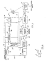
- FIGS. 1 and 1 a show an electro-pneumatic transducer system 10 which comprises an electro-pneumatic transducer assembly (constituted by a DC motor 12 and a pneumatic servo assembly or mechanism 20) and a closed loop feedback control arrangement for the transducer assembly.
- the DC motor 12 is controlled by an electronically-controlled motor servo circuit or assembly 14 which is powered by a power supply 16 operated from a 4 to 20 mA input control signal connected to the power supply 16 along a line 18.
- the DC motor 12 is mechanically constrained to the pneumatic servo assembly or mechanism 20 which has a backpressure nozzle 21 variably restricted by a cam assembly 23 connected to and driven by the DC motor 12 to thus provide a variable backpressure output along an output line 22 of the pneumatic serve assembly 20, normally in a 20.7 to 103.4 kPa (3 to 15 Ibf/in z ) output range.
- This 20.7 to 103.4 kPa (3 to 15 Ibf/in 2 ) output is linear and corresponds to the linear 4 to 20 mA electrical input provided along the input line 18.
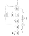
- the power supply 16 establishes dual voltages V+ and V ref along power lines 28 and 30, respectively.
- the V+ and voltage is in the range of 6.4 volts nominal and powers the motor servo circuit 14, as well as powering a desired position amplifier 38 and an amplifier circuit 46, along input lines 31 and 33, respectively.
- the V ref voltage from the power supply 16 is transmitted along the line 30 to bias up the motor servo circuitry 14 and power the pressure transducer 26 along a line 32.
- the particular electrical input signal is sent along a line 34 to a 10 ohm precision resistor located between the circuit common at a line 36 and an input to the desired position amplifier 38.
- the precision 10 ohm resistor senses the particular current level and establishes a voltage drop across itself. That voltage drop provides a counterpart voltage input to the positon amplifier 38.
- the position amplifier 38 raises the input signal level to a predetermined level and sends it along a line 40 to a difference amplifieer 42 as a set point signal compatible with the level of a feedback signal also provided to the difference amplifier 42.
- the difference amplifier 42 is the first stage of the motor servo circuit 14.
- the second input to the difference amplifier 42 is the feedback signal, which is provided on a line 44 from the amplifier circuit 46 which scales and zeroes the pressure signal provided by the pressure transducer 26 which acts as pneumatic- to-electrical converter for the 20.7 to 103.4 kPa (3 to 15 Ibf/in 2 ) output signal established at the output line 22.
- the difference amplifier 42 sensed any deviation of the feedback signal on the line 44 from the established set point signal on the line 40 and establishes an error signal on a line 48, which error signal is an amplified difference signal so long as each difference between the set point signal and feedback signal is maintained.
- This amplified error signal is supplied to an input of a proportional and integral (P & I) controller 50 where it is integrated and scaled up or down with respect to V ref .
- bi-directional rotation of the motor 12 is achieved by the voltage output of the proportional plus integral controller 50 rising or falling below the voltage reference V ref .
- the output signal is above the voltage reference V ref
- the current through the motor 12 will drive the motor 12 in first rotational direction.
- the voltage output of the proportional plus integral controller 50 is equal to V rf , no current flows through the motor and the motor is stationary. If the output voltage drops below V ref , the rotation of the motor 12 will reverse to a second rotational direction due to the voltage level applied to it crossing the V ref point.
- the amplifier circuit 46 has both a zero adjustment 60 and a span adjustment 62.
- the zeor and span adjustments 60 and 62 allow the feedback signal to be adjusted to respond over a variety of ranges.
- the predominant pressure range and pressure starting or zero point that the feedback will be adjusted for is the 20.7 to 103.4 kPA (3 to 151bf/in') signal, which is a standard for pneumatic instrumentation as 4 to 20 mA is a standard for electrical instrumentation.
- Other ranges are also available and may be set, including any 50 per cent split range desired (i.e. 0 per cent to 20.7 kPa (3 Ibf/in 2 ) and 100 per cent is 62.1 kPa (9 Ibf/ in')).
- the DC motor 12 would stop with the cam assembly 23 remaining in its last position to provide the same backpressure restriction from the nozzle 21 to the pneumatic servo assembly 20, and the last conforming pressure output signal would be maintained along the output line 22 by the pneumatic servo assembly 20.
- the pneumatic servo assembly or mechanism 20 is seen to include a regulator 64 which is connected to an air supply or unregulated high pressure air and acts to reduce the air supply pressure to a constant clean, low pressure or 151.7 + 13.8 kPa (22 + 2 Ibf/in 2 ).
- the filtered regulated air from the regulator 64 is piped to the backpressure nozzle 21 by way of an orifice 66.
- the motor servo circuit 14 causes the DC motor 12 to be rotated in either a clockwise or anticlockwise direction, which direction is dictated by a comparison of the set point and the feedback signals supplied to the control circuit 14 which acts to thus control the DC motor 12.
- the rotation of the motor 12 causes the cam assembly 23, which may be seen from Figure 5, to rotate with respect to the backpressure nozzle 21, causing a relative blockage or opening in the backpressure nozzle 21.
- the cam assembly 23, shown as the typical 20.7 to 103.4 kPA (3 to 15 Ibf/in 2 ) output cam assembly 23, is formed as a spiral-generated plane of plane section 68 having a notched portion 70 with a hub 72 located in the centre of the spiral plane 68.
- the spiral is formed to produce a linear function pressure output from the output line 22 from the backpressure nozzle 21.
- the nozzle 21 which will always seek the edge of the plane 68 aligned therewith, is positioned at a point A, a 20.7 kPa (3 Ibf/in z ) output will be produced.
- the height of the notch 70 is the range of the output signal.
- the hub 72 is used to mount the cam assmbly 23 to the shaft of the DC motor 12. Referring now to Figures 2 to 4, it will be seen that restricting the backpressure nozzle 21 causes an increase in backpressure which is piped to a bellows spring assembly 74 via a line 76. There is a directly- proportional relationship between the pressure in the bellows spring assembly 74 and the height to which it will expand.
- a bellows 78 of the assembly 74 This is determined by the construction of a bellows 78 of the assembly 74, as well as a spring 80 which is mounted in parallel with the bellows 78.
- the spring 80 acts to limit the motion of the bellows 78, thereby limiting the output range of the pneumatic output signal along the line 22 to a desired range which is determined by adjusting the spring pressure of the spring 80 by either extending or loosening the spring 80 and setting it in that particular position by way of adjusting nuts 82.
- the nuts 82 may be used to provide fine adjustment to the particular output pressure range desired. Should a different pressure range be desired, such as 20.7 to 186.2 kPa (3 to 27 Ibf/in 2 ), the spring 80 may be replaced by a different spring having a different spring coefficient.
- the backpressure nozzle 21 is rigidly mounted to a bracket assembly 84 to which the bellows 78 and the spring 80 are also mounted.
- the bracket assembly 84 is then mounted to a stationary frame member 85 through a hinge 88 to thus allow rotational motion of the backpressure nozzle 21 and the bellows 78 and sping 80 around a pivot point constituted by the hinge 88.
Landscapes
- Engineering & Computer Science (AREA)
- Physics & Mathematics (AREA)
- Fluid Mechanics (AREA)
- General Engineering & Computer Science (AREA)
- Mechanical Engineering (AREA)
- Theoretical Computer Science (AREA)
- General Physics & Mathematics (AREA)
- Automation & Control Theory (AREA)
- Supply Devices, Intensifiers, Converters, And Telemotors (AREA)
- Servomotors (AREA)
Applications Claiming Priority (2)
| Application Number | Priority Date | Filing Date | Title |
|---|---|---|---|
| US46920083A | 1983-02-24 | 1983-02-24 | |
| US469200 | 1990-01-24 |
Publications (3)
| Publication Number | Publication Date |
|---|---|
| EP0120594A2 EP0120594A2 (en) | 1984-10-03 |
| EP0120594A3 EP0120594A3 (en) | 1985-07-10 |
| EP0120594B1 true EP0120594B1 (en) | 1988-06-22 |
Family
ID=23862855
Family Applications (1)
| Application Number | Title | Priority Date | Filing Date |
|---|---|---|---|
| EP84301086A Expired EP0120594B1 (en) | 1983-02-24 | 1984-02-20 | Electro-pneumatic transducer assemblies |
Country Status (12)
| Country | Link |
|---|---|
| EP (1) | EP0120594B1 (enExample) |
| JP (1) | JPS59164401A (enExample) |
| KR (1) | KR890003863B1 (enExample) |
| AU (1) | AU566328B2 (enExample) |
| BR (1) | BR8400626A (enExample) |
| CA (1) | CA1225450A (enExample) |
| DE (1) | DE3472287D1 (enExample) |
| ES (1) | ES8507271A1 (enExample) |
| HK (1) | HK2689A (enExample) |
| IN (1) | IN160712B (enExample) |
| MX (1) | MX154835A (enExample) |
| SG (1) | SG58388G (enExample) |
Cited By (1)
| Publication number | Priority date | Publication date | Assignee | Title |
|---|---|---|---|---|
| CN101782094A (zh) * | 2009-01-14 | 2010-07-21 | Abb技术股份公司 | 用于在气动调节驱动器的受控电动-气动阀中找到开放点的方法和电子装置 |
Families Citing this family (1)
| Publication number | Priority date | Publication date | Assignee | Title |
|---|---|---|---|---|
| JPH0792084B2 (ja) * | 1986-08-18 | 1995-10-09 | 日本ベ−レ−株式会社 | パルス−空気圧変換装置 |
Citations (1)
| Publication number | Priority date | Publication date | Assignee | Title |
|---|---|---|---|---|
| US3334642A (en) * | 1965-08-16 | 1967-08-08 | Fisher Governor Co | Electro-pneumatic transducer |
Family Cites Families (8)
| Publication number | Priority date | Publication date | Assignee | Title |
|---|---|---|---|---|
| FR1089975A (fr) * | 1953-06-17 | 1955-03-25 | Regulateurs Francel | Dispositif à modulation pneumatique pour la transmission automatique d'impulsions de commande |
| JPS458969Y1 (enExample) * | 1966-06-10 | 1970-04-27 | ||
| DE6927354U (de) * | 1968-07-10 | 1972-08-10 | Diesel Kiki Co | Vorrichtung zum umwandeln elektrischer signale in fluddrucksignale. |
| US3819960A (en) * | 1972-05-01 | 1974-06-25 | Love Controls Corp | Controller circuit |
| JPS4924888U (enExample) * | 1972-06-12 | 1974-03-02 | ||
| JPS5445463A (en) * | 1977-09-19 | 1979-04-10 | Yokogawa Hokushin Electric Corp | Pressure generator |
| US4329910A (en) * | 1978-12-21 | 1982-05-18 | The Foxboro Company | Transducer assembly providing position output proportional to electrical input signal |
| SE420639B (sv) * | 1979-03-01 | 1981-10-19 | Saab Scania Ab | Signalomvandlare enhet for omvandling av en elektrisk reglersignal till en pneumatisk signal med ett piezoelektrisk element |
-
1984
- 1984-02-09 BR BR8400626A patent/BR8400626A/pt unknown
- 1984-02-20 MX MX200392A patent/MX154835A/es unknown
- 1984-02-20 DE DE8484301086T patent/DE3472287D1/de not_active Expired
- 1984-02-20 EP EP84301086A patent/EP0120594B1/en not_active Expired
- 1984-02-21 AU AU24788/84A patent/AU566328B2/en not_active Ceased
- 1984-02-22 CA CA000447995A patent/CA1225450A/en not_active Expired
- 1984-02-22 IN IN125/CAL/84A patent/IN160712B/en unknown
- 1984-02-22 ES ES529970A patent/ES8507271A1/es not_active Expired
- 1984-02-23 JP JP59031557A patent/JPS59164401A/ja active Granted
- 1984-02-23 KR KR1019840000886A patent/KR890003863B1/ko not_active Expired
-
1988
- 1988-09-08 SG SG583/88A patent/SG58388G/en unknown
-
1989
- 1989-01-12 HK HK26/89A patent/HK2689A/en not_active IP Right Cessation
Patent Citations (1)
| Publication number | Priority date | Publication date | Assignee | Title |
|---|---|---|---|---|
| US3334642A (en) * | 1965-08-16 | 1967-08-08 | Fisher Governor Co | Electro-pneumatic transducer |
Cited By (1)
| Publication number | Priority date | Publication date | Assignee | Title |
|---|---|---|---|---|
| CN101782094A (zh) * | 2009-01-14 | 2010-07-21 | Abb技术股份公司 | 用于在气动调节驱动器的受控电动-气动阀中找到开放点的方法和电子装置 |
Also Published As
| Publication number | Publication date |
|---|---|
| CA1225450A (en) | 1987-08-11 |
| IN160712B (enExample) | 1987-08-01 |
| AU2478884A (en) | 1984-08-30 |
| EP0120594A3 (en) | 1985-07-10 |
| JPH0428921B2 (enExample) | 1992-05-15 |
| BR8400626A (pt) | 1984-10-02 |
| ES529970A0 (es) | 1985-08-16 |
| EP0120594A2 (en) | 1984-10-03 |
| MX154835A (es) | 1987-12-16 |
| JPS59164401A (ja) | 1984-09-17 |
| SG58388G (en) | 1989-01-27 |
| ES8507271A1 (es) | 1985-08-16 |
| KR840007962A (ko) | 1984-12-11 |
| DE3472287D1 (en) | 1988-07-28 |
| HK2689A (en) | 1989-01-20 |
| KR890003863B1 (ko) | 1989-10-05 |
| AU566328B2 (en) | 1987-10-15 |
Similar Documents
| Publication | Publication Date | Title |
|---|---|---|
| US4481967A (en) | Control circuit for current to pressure converter | |
| US4789826A (en) | System for sensing the angular position of a rotatable member using a hall effect transducer | |
| CA1157928A (en) | Current to pressure converter apparatus | |
| US5465757A (en) | Electro-hydraulic fluid metering and control device | |
| US4579137A (en) | Electro-pneumatic current to pressure transducer and pneumatic and electronic control circuits therefor | |
| US4630631A (en) | Pneumatic servo assembly for an electro-pneumatic converter | |
| US5452153A (en) | Servo controlled magnetic head positioner | |
| US4610263A (en) | Pneumatic servo assembly for an electro pneumatic converter | |
| EP0120594B1 (en) | Electro-pneumatic transducer assemblies | |
| EP0174748B1 (en) | Position transmitters | |
| EP0120593B1 (en) | Electro-pneumatic control systems | |
| EP0316292B1 (en) | Zero and span adjustment circuit for current/pressure transducer | |
| CA1224721A (en) | Pneumatic position controller | |
| CA1224260A (en) | Pneumatic servo assembly for an electro-pneumatic converter | |
| US4965475A (en) | Offset adjust for moving coil transducer | |
| US4329910A (en) | Transducer assembly providing position output proportional to electrical input signal | |
| US4566340A (en) | Force transducer | |
| JPH0416645B2 (enExample) | ||
| CA1037504A (en) | Damper mechanism | |
| JPS5810208A (ja) | 流体制御装置 | |
| CA1151897A (en) | Force transducer | |
| JPH0618010B2 (ja) | 自動圧力調節装置 | |
| JP3469378B2 (ja) | 電空変換器 | |
| CA1152614A (en) | Control circuit for current to pressure converter | |
| MAMZIC | 2.4 Controllers—Pneumatic |
Legal Events
| Date | Code | Title | Description |
|---|---|---|---|
| PUAI | Public reference made under article 153(3) epc to a published international application that has entered the european phase |
Free format text: ORIGINAL CODE: 0009012 |
|
| AK | Designated contracting states |
Designated state(s): DE FR GB IT |
|
| PUAL | Search report despatched |
Free format text: ORIGINAL CODE: 0009013 |
|
| AK | Designated contracting states |
Designated state(s): DE FR GB IT |
|
| 17P | Request for examination filed |
Effective date: 19851122 |
|
| 17Q | First examination report despatched |
Effective date: 19861217 |
|
| ITF | It: translation for a ep patent filed | ||
| GRAA | (expected) grant |
Free format text: ORIGINAL CODE: 0009210 |
|
| AK | Designated contracting states |
Kind code of ref document: B1 Designated state(s): DE FR GB IT |
|
| REF | Corresponds to: |
Ref document number: 3472287 Country of ref document: DE Date of ref document: 19880728 |
|
| ET | Fr: translation filed | ||
| PLBE | No opposition filed within time limit |
Free format text: ORIGINAL CODE: 0009261 |
|
| STAA | Information on the status of an ep patent application or granted ep patent |
Free format text: STATUS: NO OPPOSITION FILED WITHIN TIME LIMIT |
|
| 26N | No opposition filed | ||
| REG | Reference to a national code |
Ref country code: GB Ref legal event code: 732 |
|
| ITTA | It: last paid annual fee | ||
| PGFP | Annual fee paid to national office [announced via postgrant information from national office to epo] |
Ref country code: FR Payment date: 19960118 Year of fee payment: 13 |
|
| PGFP | Annual fee paid to national office [announced via postgrant information from national office to epo] |
Ref country code: DE Payment date: 19960119 Year of fee payment: 13 |
|
| PGFP | Annual fee paid to national office [announced via postgrant information from national office to epo] |
Ref country code: GB Payment date: 19960129 Year of fee payment: 13 |
|
| PG25 | Lapsed in a contracting state [announced via postgrant information from national office to epo] |
Ref country code: GB Effective date: 19970220 |
|
| GBPC | Gb: european patent ceased through non-payment of renewal fee |
Effective date: 19970220 |
|
| PG25 | Lapsed in a contracting state [announced via postgrant information from national office to epo] |
Ref country code: FR Effective date: 19971030 |
|
| PG25 | Lapsed in a contracting state [announced via postgrant information from national office to epo] |
Ref country code: DE Effective date: 19971101 |
|
| REG | Reference to a national code |
Ref country code: FR Ref legal event code: ST |