EP0120186A2 - Apparatus for automatic instruction parity error recovery - Google Patents
Apparatus for automatic instruction parity error recovery Download PDFInfo
- Publication number
- EP0120186A2 EP0120186A2 EP84100226A EP84100226A EP0120186A2 EP 0120186 A2 EP0120186 A2 EP 0120186A2 EP 84100226 A EP84100226 A EP 84100226A EP 84100226 A EP84100226 A EP 84100226A EP 0120186 A2 EP0120186 A2 EP 0120186A2
- Authority
- EP
- European Patent Office
- Prior art keywords
- instruction
- processor
- parity
- address
- error
- Prior art date
- Legal status (The legal status is an assumption and is not a legal conclusion. Google has not performed a legal analysis and makes no representation as to the accuracy of the status listed.)
- Granted
Links
Images

Classifications
-
- G—PHYSICS
- G06—COMPUTING; CALCULATING OR COUNTING
- G06F—ELECTRIC DIGITAL DATA PROCESSING
- G06F11/00—Error detection; Error correction; Monitoring
- G06F11/07—Responding to the occurrence of a fault, e.g. fault tolerance
- G06F11/14—Error detection or correction of the data by redundancy in operation
- G06F11/1402—Saving, restoring, recovering or retrying
- G06F11/1405—Saving, restoring, recovering or retrying at machine instruction level
- G06F11/141—Saving, restoring, recovering or retrying at machine instruction level for bus or memory accesses
Abstract
Description
- This invention relates to bit error detection and recovery, and more particularly to an apparatus and method for automatic instruction parity error recovery in a digital computer system.
- In many computer systems, and especially in small remote attached devices, internal instructions are read from storage in a sequence to control the operation of the processor. In the prior art, many of these remote devices contained only read-only storage (ROS) where the processor instructions were unalterably stored at the time of manufacture. When the instructions were read from the storage by the processor, a parity checker would determine if the instruction had good parity (contained the correct number of ones). If the parity was bad, these systems normally stopped the processor and set an indicator informing the operator of the device failure.
- However, in many newer systems, various and different programs, sometimes large and complex, are executed in the remote devices, such as display workstations, allowing many different functions to be performed by the devices. Typically, the instructions for the remote device processor are loaded from either a local media, such as a diskette drive attached to the device, or from a remote host system, such as a large central processor, into a writeable random access memory (RAM) within the remote device. These RAM storage devices are generally affected by environmental conditions and have a higher failure rate than the ROS type of storage devices. Temporary or permanent device failures may occur more frequently due to bits being altered in the instruction storage by storage device failure or external environmental conditions. In prior art systems, this normally would result in the processor being halted and an indicator being set to inform the operator of the failure, resulting in loss of utilization of the device, loss of information being processed at the time of failure, and loss of operator time in reloading and restarting the device. When the device was remotely attached to a central host system, there was no automatic record made in the host system of the failure because, with an instruction error, the remote device's processor was stopped and communications with the host system was lost. This made the maintenance and problem isolation procedures for these remote devices very difficult since no record of instruction storage failure was sent to the host system.
- Accordingly, one object of the present invention is to provide an apparatus and a method for detecting parity errors in the instruction stream of an information processor and to recover the processor from the parity errors without operator intervention, by reloading the instruction causing the parity error into the memory of the information processor and restarting the processor at the address where the parity error occurred, thus preventing loss of processed information.
- The foregoing and other objects are accomplished in accordance with the present invention by providing a recovery system for uncorrectable parity errors encountered by an information processor during instruction "fetch" from a RAM instruction storage device. An instruction parity checker presents a signal to the recovery system indicating that the instruction fetched from storage has an unrecoverable parity error. A No-Operation instruction is sent to the processor in place of the instruction with the unrecoverable parity error and the address of the faulty instruction is loaded into a register. The processor to instruction storage address bus is isolated from the instruction storage unit and a previously defined branch instruction to the error recovery routine is presented for the processor's next instruction fetch. The processor to instruction storage address bus is then reactivated to the storage unit and the processor begins executing the error recovery routine.
- The error recovery routine saves the processor state and sends an error signal to the host system via the communication attachment. The error recovery routine reads the storage address of the failing instruction from the register, updates failure counters, and determines if this address has had a predetermined maximum number of sequential failures or if the storage unit has exceeded a predetermined maximum number of failures allowed. If the maximum number of failures has not been exceeded, the recovery routine sends the host system an instruction parity error indication, the address of the failure, and a reload indicator. The error recovery routine then links to the loader to reload the faulty instruction segment from the host system. After reloading the instruction segment, the processor's state is restored and the processor is branched back to the address it was executing from at the time of failure.
- If the maximum number of failures has been exceeded, the error recovery routine sends the host system an instruction parity error indication, the address of the failure, and a retry exceeded indicator when the host system requests unit status. The error recovery routine then shuts down the communication link to the host system and sets a local indicator to inform the operator of an unrecoverable device error.
- A best mode for carrying out the invention is now described in reference to the drawings wherein :
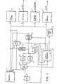
- FIG. 1 is a block diagram of a computer system employing the present invention.
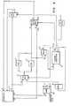
- FIG. 2 shows in greater detail the inventive portion of FIG. 1.
- FIG. 3 shows a flow diagram of the operation of the parity error recovery routine of the present invention.
- Referring to FIG. 1, a block diagram of a remote device processing system that includes a
processor 2 and instruction storage units 3 and 4, and incorporates the present invention is shown. Additionally, the remote device includes data storage 5, acommunication device 6 to a host system, a keyboard adapter 7, and aCRT adapter 8 all of which are interconnected by adata bus 9. The programload control logic 25 allows the processor to read and write instructions to the writeable instruction storage unit 3. The host system to which the remote device is connected by thecommunication device 6 may be any of the large or small so called mainframe computers having resident operating systems and capable of controlling a plurality of remote terminal devices, e.g., the IBM System 370 and the IBM 5520 Administrative System. Thedata bus 9 couples all addresses, data and control information between theprocessor 2, data storage 5, and the keyboard andCRT interfaces 7 and 8 respectively. Aninstruction address bus 10 andinstruction data bus 11 couples instruction addresses, instruction data, and control information between theprocessor 2 and the instruction storages 3 and 4. An instruction parity generator/checker 17 creates parity information for instructions being stored in the instruction storage unit 3 and checks instruction parity when read by theprocessor 2 from storage units 3 and 4. It should be known and understood at this point that the device configuration in FIG. 1 is exemplary and that other configurations may be utilized which incorporate the present invention. - The instruction storage unit is typically Read Only Storage (ROS) in a remote device configuration to facilitate a set of instructions to provide power-on diagnostic procedures and a program loader to load the Writable Random Access Memory (RAM) unit 3 with the application program (set of instructions) from the host system. The Instruction Parity Error Recovery procedure, a part of the present invention, is incorporated in the (ROS) instruction storage unit 4. The additional component blocks which implement the present invention are the
control sequencer 12 which controls the 2 to 1 instructionbus address multiplexor 13, the errorrecovery address logic 14, the No-Operation instruction logic 15, and the failureaddress holding register 16. - The
control sequencer 12 receives two signals from the Instruction parity generator/checker 17. These control signals indicate whether a ROS storage 4 parity error or a RAM storage 3 parity error has occurred. If a ROS storage parity error is signalled thecontrol sequencer 12 sets the storage check indicator 18 on the operator panel. - Referring to FIG. 2 the
processor 2 loads the instruction address onto theinstruction address bus 10 and sets the instruction addressvalid signal 19. Thetimer 28 controls the memory cycle and is set to T0, starting the memory cycle on either the ROS storage unit 4 or RAM storage unit 3 depending on the address supplied by theinstruction address bus 10. Thetimer 28 advances one T time each processor clock cycle. At T6 the data from storage is presented to theparity checker 17 from thestorage data bus 24 and the parity is checked. At T8 theprocessor 2 presents the sampleinstruction bus signal 20 and loads the instruction from theinstruction data bus 11 into theprocessor 2 for processing. - If the parity checker detects a RAM parity error, it sets the instruction RAM
parity error signal 21 to thecontrol sequencer 12. Thecontrol sequencer 12 activates the No-Operation instruction logic 15 which loads theinstruction data bus 11 with the No-Operation instruction at T7 time. Thecontrol sequencer 12 then sets the loaderror address signal 22 to the failureaddress holding register 16 which causes the instruction address on theinstruction address bus 10 to be loaded into theregister 16. Thecontrol sequencer 12 then sets an errorrecovery pending latch 23 and signals the 2 to 1 instructionaddress bus multiplexor 13 to select the errorrecovery address logic 14 for the next processor instruction fetch. Theprocessor 2 processes the No-Operation instruction then sets the instruction addressvalid signal 19 to the storage units. The memory cycle reads an instruction from the address specified by the errorrecovery address logic 14. This address selects a branch to error recovery procedure instruction in ROS 4. This branch instruction is loaded onto theinstruction data bus 11 and is read by the processor at T8 time. At T9 time thecontrol sequencer 12 resets the errorrecovery pending latch 23 and resets the 2 to 1 instructionaddress bus multiplexor 14 to resume gating the processor'sinstruction address bus 10 to the storage units 3 and 4. Thecontrol sequencer 12 has now completed it's parity error recovery cycle. - The error recovery routine, given processor control by the aforementioned error recovery logic, is detailed in the Program Design Language (PDL) description shown in Table 1. It should be known and understood that the error recovery routine described herein is exemplary and that modifications may be utilized to perform the function within the scope of the present invention. Functionally, the error recovery routine will be described with reference to FIG. 3.


- In reference to Figure 3 the parity error recovery routine starts in
block 30 and inblock 31 the processor condition or state at the occurrence of the error is saved in a plurality of predetermined storage locations. In block 32 the address of the instruction causing the parity error is read intoregister 1. In block 33 a test is conducted to determine whether the processor is in the diagnostic mode. If the processor is operating in the diagnostic mode then the error recovery routine branches to block 40 wherein the processor registers are restored with the processor state and the diagnostic routine is branched to inblock 41. The operation of the diagnostic routine referred to inblock 41 and the operation of the processor in a diagnostic mode is not directly related to the present invention and will not be discussed in further detail. - Referring back to block 33 of FIG. 3, if the processor is not in the diagnostic mode, then a parity error is assumed to have occurred during normal instruction fetch and processing continues in
block 34 wherein a predefined storage location to keep track of the number of instruction parity errors occurring in the RAM memory is incremented by 1. Inblock 35 the address of the last instruction parity error is moved to workingregister 2. Inblock 36 the address of the current instruction parity error which was previously read intoregister 1 in block 32 is moved to the last failure address storage location. This places the current error instruction address in a position to become the address of the last instruction failure when the next failure occurs. In block 37 a test is conducted to determine if the address stored inregister 1, which is the address of the current instruction having a parity error, is equal to the address stored inregister 2 which is the address of the last instruction having a parity error. If the two addresses are the same, then a counter is incremented inblock 31 to keep a cumulative count of the number of instruction parity errors occurring at the same address. If the address inregister 1 is not equal to the address inregister 2 then the same address counter is cleared atblock 38. - Processing continues in block 42 wherein a storage location defined as
status 1 is incremented to indicate that an instruction parity error has occurred in RAM storage unit 3. Inblock 43status 1 and the same address counter are tested to determine whether each is equal to a predetermined maximum number of instruction parity errors allowed. This predetermined maximum number of parity errors allowable in the RAM storage unit 3 is purely a designer's choice used to establish a point at which the occurrence of errors in the RAM storage unit 3 is great enough to require replacement of the RAM storage. If the maximum allowable number of errors has occurred in either the current failing address or in the RAM storage unit 3, thenstatus 2 is set inblock 53 to indicate that the number of retries for the memory unit has been exceeded. If the failure counts are less than the maximum allowable, then inblock 44status 2 is set to request a reload from the host system of the instruction having the parity error. - Processing continues to block 45 wherein the current failing instruction address stored in
register 1 is moved to the status 3 storage location. Inblock 44 an error indicator is set for the next poll to signal the host system that an instruction parity error has occurred in the remote system. The status information for the remote system is then accessed by the host system on its next poll of the remote system. Inblock 47 ifstatus 2 was set to reload the error instruction inblock 44, then the "program load routine" is branched to inblock 49 to accept program load commands and load instructions from the host system to reload the instruction at the address defined in status 3. In block 51 the registers 1-7 are accessed to restore the processor's state and processing of the application program continues atblock 52. - Referring back to block 47, if
status 2 was set to indicate that the retry for the RAM storage unit 3 was exceeded inblock 53 then processing continues to block 48 wherein the communication line to the host system is reset (disconnected) and an indicator is set on the remote system control panel to notify the operator that an uncorrectable storage error has occurred in the remote system. Processing is then halted inblock 50. - The error poll signal and the status information which is sent to the host processing system in
block 46 is recorded in the host processing system and may be later retrieved during routine preventive maintenance to provide information on errors occurring in the remote attached devices. - The present invention has been specifically described in the preferred embodiment as operating in a remote terminal system which is connected to a host processing system from which the application program instructions are offloaded to the remote system. However, it will be readily recognized by those having ordinary skill in the art that this error recovery routine is applicable to an information processing system wherein the application programs are stored on an external device such as a disk file and brought into the processor's instruction RAM memory only as needed. In this operating environment, the parity error recovery routine would initiate a reload of the error instruction from the external storage device to the system RAM memory.
- This invention is not to be limited by the embodiment shown in the drawings and described in the description, which is given by way of example and not of limitation.
Claims (6)
Applications Claiming Priority (2)
| Application Number | Priority Date | Filing Date | Title |
|---|---|---|---|
| US478574 | 1983-03-24 | ||
| US06/478,574 US4538265A (en) | 1983-03-24 | 1983-03-24 | Method and apparatus for instruction parity error recovery |
Publications (3)
| Publication Number | Publication Date |
|---|---|
| EP0120186A2 true EP0120186A2 (en) | 1984-10-03 |
| EP0120186A3 EP0120186A3 (en) | 1988-01-27 |
| EP0120186B1 EP0120186B1 (en) | 1990-12-19 |
Family
ID=23900476
Family Applications (1)
| Application Number | Title | Priority Date | Filing Date |
|---|---|---|---|
| EP84100226A Expired EP0120186B1 (en) | 1983-03-24 | 1984-01-11 | Apparatus for automatic instruction parity error recovery |
Country Status (4)
| Country | Link |
|---|---|
| US (1) | US4538265A (en) |
| EP (1) | EP0120186B1 (en) |
| JP (1) | JPS59174952A (en) |
| DE (1) | DE3483750D1 (en) |
Cited By (2)
| Publication number | Priority date | Publication date | Assignee | Title |
|---|---|---|---|---|
| AU639368B2 (en) * | 1990-08-20 | 1993-07-22 | Comalco Aluminium Limited | Improved aluminium smelting cell |
| CN109739777A (en) * | 2018-12-25 | 2019-05-10 | 清华大学 | Local reliable flash memory storage method and system with distributed collaboration design |
Families Citing this family (19)
| Publication number | Priority date | Publication date | Assignee | Title |
|---|---|---|---|---|
| JPS6269327A (en) * | 1985-09-24 | 1987-03-30 | Hitachi Ltd | Automatic recovery system |
| DE3678893D1 (en) * | 1985-10-03 | 1991-05-29 | Mitsubishi Electric Corp | COMPUTER PROGRAM DEBUG SYSTEM. |
| US4868744A (en) * | 1986-03-03 | 1989-09-19 | International Business Machines Corporation | Method for restarting a long-running, fault-tolerant operation in a transaction-oriented data base system without burdening the system log |
| US5398265A (en) * | 1988-11-10 | 1995-03-14 | Hughes Aircraft Company | Computer subsystem reset by address dependent RC discharge |
| US5056091A (en) * | 1990-03-15 | 1991-10-08 | Hewlett-Packard Company | Method for handling errors detected in a computer system |
| EP0596144A1 (en) * | 1992-10-07 | 1994-05-11 | International Business Machines Corporation | Hierarchical memory system for microcode and means for correcting errors in the microcode |
| JPH06214897A (en) * | 1992-12-14 | 1994-08-05 | E Syst Inc | Method for minimization of loss of data stored in peripheral device in detection of error status |
| US5872910A (en) * | 1996-12-27 | 1999-02-16 | Unisys Corporation | Parity-error injection system for an instruction processor |
| US6615375B1 (en) | 2000-02-03 | 2003-09-02 | International Business Machines Corporation | Method and apparatus for tolerating unrecoverable errors in a multi-processor data processing system |
| US6745346B2 (en) * | 2000-12-08 | 2004-06-01 | Intel Corporation | Method for efficiently identifying errant processes in a computer system by the operating system (OS) for error containment and error recovery |
| US7093190B1 (en) * | 2002-07-12 | 2006-08-15 | Unisys Corporation | System and method for handling parity errors in a data processing system |
| US7278062B2 (en) * | 2003-01-09 | 2007-10-02 | Freescale Semiconductor, Inc. | Method and apparatus for responding to access errors in a data processing system |
| US7373558B2 (en) * | 2004-09-23 | 2008-05-13 | Intel Corporation | Vectoring process-kill errors to an application program |
| JP2007018454A (en) * | 2005-07-11 | 2007-01-25 | Toshiba Corp | Microprocessor |
| US7447948B2 (en) * | 2005-11-21 | 2008-11-04 | Intel Corporation | ECC coding for high speed implementation |
| JP5129450B2 (en) * | 2006-01-16 | 2013-01-30 | ルネサスエレクトロニクス株式会社 | Information processing device |
| JP2009187049A (en) * | 2008-02-01 | 2009-08-20 | Fujitsu Ltd | Device |
| JP4334598B1 (en) * | 2008-04-16 | 2009-09-30 | 株式会社東芝 | Information processing apparatus and error correction method |
| JP6304007B2 (en) * | 2014-12-09 | 2018-04-04 | 株式会社デンソー | Microcontroller |
Citations (6)
| Publication number | Priority date | Publication date | Assignee | Title |
|---|---|---|---|---|
| GB1264066A (en) * | 1970-06-24 | 1972-02-16 | ||
| GB1315673A (en) * | 1970-06-12 | 1973-05-02 | Robotron Veb K | Digital computer installations |
| US4231089A (en) * | 1978-12-15 | 1980-10-28 | Digital Equipment Corporation | Data processing system with apparatus for correcting microinstruction errors |
| FR2492132A1 (en) * | 1980-10-09 | 1982-04-16 | Nippon Electric Co | ERROR RECTIFICATION SYSTEM OF A MULTIPROCESSOR SYSTEM FOR ERROR RECOGNITION BY TRANSFERRING STATUS SIGNALS FROM ONE PROCESSOR TO ANOTHER PROCESSOR WITHOUT USING A MEMORY |
| JPS57136263A (en) * | 1981-02-17 | 1982-08-23 | Canon Inc | Automatic resetting device of microcomputer |
| JPS58199499A (en) * | 1982-05-17 | 1983-11-19 | Toshiba Corp | Data processor |
Family Cites Families (8)
| Publication number | Priority date | Publication date | Assignee | Title |
|---|---|---|---|---|
| US3345614A (en) * | 1965-01-12 | 1967-10-03 | Friden Inc | Data translation system |
| US3613078A (en) * | 1969-09-23 | 1971-10-12 | Computer Sciences Corp | Apparatus for monitoring binary coded communications |
| IT1046598B (en) * | 1974-05-16 | 1980-07-31 | Honeywell Inf Systems | INTERFACE FOR CONNECTION OF PERIPHERAL EQUIPMENT TO A COMPUTER PROVIDED WITH SIGNALING AND DISTINCTION MECHANISMS TRANSLATING TYPES OF ERROR |
| US3917933A (en) * | 1974-12-17 | 1975-11-04 | Sperry Rand Corp | Error logging in LSI memory storage units using FIFO memory of LSI shift registers |
| JPS5258337A (en) * | 1975-11-10 | 1977-05-13 | Hitachi Ltd | Micro program control unit |
| US4053751A (en) * | 1976-04-28 | 1977-10-11 | Bell Telephone Laboratories, Incorporated | Adaptable exerciser for a memory system |
| US4360917A (en) * | 1979-02-07 | 1982-11-23 | The Warner & Swasey Company | Parity fault locating means |
| JPS57169857A (en) * | 1981-04-13 | 1982-10-19 | Mitsubishi Electric Corp | Control storage device |
-
1983
- 1983-03-24 US US06/478,574 patent/US4538265A/en not_active Expired - Fee Related
-
1984
- 1984-01-10 JP JP59001439A patent/JPS59174952A/en active Granted
- 1984-01-11 EP EP84100226A patent/EP0120186B1/en not_active Expired
- 1984-01-11 DE DE8484100226T patent/DE3483750D1/en not_active Expired - Fee Related
Patent Citations (6)
| Publication number | Priority date | Publication date | Assignee | Title |
|---|---|---|---|---|
| GB1315673A (en) * | 1970-06-12 | 1973-05-02 | Robotron Veb K | Digital computer installations |
| GB1264066A (en) * | 1970-06-24 | 1972-02-16 | ||
| US4231089A (en) * | 1978-12-15 | 1980-10-28 | Digital Equipment Corporation | Data processing system with apparatus for correcting microinstruction errors |
| FR2492132A1 (en) * | 1980-10-09 | 1982-04-16 | Nippon Electric Co | ERROR RECTIFICATION SYSTEM OF A MULTIPROCESSOR SYSTEM FOR ERROR RECOGNITION BY TRANSFERRING STATUS SIGNALS FROM ONE PROCESSOR TO ANOTHER PROCESSOR WITHOUT USING A MEMORY |
| JPS57136263A (en) * | 1981-02-17 | 1982-08-23 | Canon Inc | Automatic resetting device of microcomputer |
| JPS58199499A (en) * | 1982-05-17 | 1983-11-19 | Toshiba Corp | Data processor |
Non-Patent Citations (3)
| Title |
|---|
| IBM TECHNICAL DISCLOSURE BULLETIN, vol. 23, no. 11, April 1981, page 5271, New York, US; S.P. DALE et al.: "Instruction nullification by saving and restoring architected data" * |
| PATENT ABSTRACTS OF JAPAN, vol. 6, no. 237 (P-157)[1115], 25th November 1982; & JP 57136263 A (CANON K.K.) 23-08-1982 * |
| PATENT ABSTRACTS OF JAPAN, vol. 8, no. 48 (P-258)[1485], 3rd March 1984; & JP 58199499 (TOKYO SHIBAURA DENKI K.K.) 19-11-1983 (Cat. P,X) * |
Cited By (3)
| Publication number | Priority date | Publication date | Assignee | Title |
|---|---|---|---|---|
| AU639368B2 (en) * | 1990-08-20 | 1993-07-22 | Comalco Aluminium Limited | Improved aluminium smelting cell |
| CN109739777A (en) * | 2018-12-25 | 2019-05-10 | 清华大学 | Local reliable flash memory storage method and system with distributed collaboration design |
| CN109739777B (en) * | 2018-12-25 | 2020-08-04 | 清华大学 | Reliable flash memory storage method and system based on local and distributed collaborative design |
Also Published As
| Publication number | Publication date |
|---|---|
| JPS59174952A (en) | 1984-10-03 |
| EP0120186A3 (en) | 1988-01-27 |
| EP0120186B1 (en) | 1990-12-19 |
| DE3483750D1 (en) | 1991-01-31 |
| US4538265A (en) | 1985-08-27 |
| JPH0325814B2 (en) | 1991-04-09 |
Similar Documents
| Publication | Publication Date | Title |
|---|---|---|
| EP0120186B1 (en) | Apparatus for automatic instruction parity error recovery | |
| US4371754A (en) | Automatic fault recovery system for a multiple processor telecommunications switching control | |
| CA1235520A (en) | Maintenance subsystem for computer network | |
| EP0180128B1 (en) | User interface processor for computer network | |
| EP0784272B1 (en) | Input/output controller | |
| EP0414379A2 (en) | Method of handling errors in software | |
| US4231089A (en) | Data processing system with apparatus for correcting microinstruction errors | |
| JPS5851292B2 (en) | Diagnosis/debug calculation system | |
| US4395755A (en) | Information processing system and logout process therefor | |
| US4550278A (en) | Control device | |
| JPH06208477A (en) | Fault-tolerant computer with online re-incorporation and interruption / restart | |
| US5615370A (en) | Computer system with automatic degradation/initialization function | |
| US4841474A (en) | Computer system with work stations at remote positions and reserve battery power supply | |
| JPH05181824A (en) | Data management system | |
| CN115248627A (en) | Method, system and computer program product for storing finite state machine state data | |
| JPH11120154A (en) | Device and method for access control in computer system | |
| JP3315266B2 (en) | Self-diagnosis status display method | |
| JPH0651918A (en) | Semiconductor disk device | |
| JPS62182952A (en) | Magnetic disk control device | |
| JPH07219796A (en) | Information processor | |
| JPS6367646A (en) | Information processing system with faulty area separating function | |
| JPS6258344A (en) | Fault recovering device | |
| GAWHON | SAFEGUARD Data-Processing System | |
| JPH04153840A (en) | Information processing system | |
| JPH04252339A (en) | Isolation processing system for faulty processor |
Legal Events
| Date | Code | Title | Description |
|---|---|---|---|
| PUAI | Public reference made under article 153(3) epc to a published international application that has entered the european phase |
Free format text: ORIGINAL CODE: 0009012 |
|
| AK | Designated contracting states |
Designated state(s): DE FR GB |
|
| 17P | Request for examination filed |
Effective date: 19841123 |
|
| PUAL | Search report despatched |
Free format text: ORIGINAL CODE: 0009013 |
|
| AK | Designated contracting states |
Kind code of ref document: A3 Designated state(s): DE FR GB |
|
| 17Q | First examination report despatched |
Effective date: 19890428 |
|
| GRAA | (expected) grant |
Free format text: ORIGINAL CODE: 0009210 |
|
| AK | Designated contracting states |
Kind code of ref document: B1 Designated state(s): DE FR GB |
|
| REF | Corresponds to: |
Ref document number: 3483750 Country of ref document: DE Date of ref document: 19910131 |
|
| ET | Fr: translation filed | ||
| PLBE | No opposition filed within time limit |
Free format text: ORIGINAL CODE: 0009261 |
|
| STAA | Information on the status of an ep patent application or granted ep patent |
Free format text: STATUS: NO OPPOSITION FILED WITHIN TIME LIMIT |
|
| 26N | No opposition filed | ||
| PGFP | Annual fee paid to national office [announced via postgrant information from national office to epo] |
Ref country code: GB Payment date: 19921222 Year of fee payment: 10 |
|
| PGFP | Annual fee paid to national office [announced via postgrant information from national office to epo] |
Ref country code: FR Payment date: 19921223 Year of fee payment: 10 |
|
| PGFP | Annual fee paid to national office [announced via postgrant information from national office to epo] |
Ref country code: DE Payment date: 19930127 Year of fee payment: 10 |
|
| PG25 | Lapsed in a contracting state [announced via postgrant information from national office to epo] |
Ref country code: GB Effective date: 19940111 |
|
| GBPC | Gb: european patent ceased through non-payment of renewal fee |
Effective date: 19940111 |
|
| PG25 | Lapsed in a contracting state [announced via postgrant information from national office to epo] |
Ref country code: FR Effective date: 19940930 |
|
| PG25 | Lapsed in a contracting state [announced via postgrant information from national office to epo] |
Ref country code: DE Effective date: 19941001 |
|
| REG | Reference to a national code |
Ref country code: FR Ref legal event code: ST |