EP0120156A2 - Electromechanical manipulator assembly - Google Patents
Electromechanical manipulator assembly Download PDFInfo
- Publication number
- EP0120156A2 EP0120156A2 EP83303065A EP83303065A EP0120156A2 EP 0120156 A2 EP0120156 A2 EP 0120156A2 EP 83303065 A EP83303065 A EP 83303065A EP 83303065 A EP83303065 A EP 83303065A EP 0120156 A2 EP0120156 A2 EP 0120156A2
- Authority
- EP
- European Patent Office
- Prior art keywords
- assembly
- manipulator
- cylinder
- piston
- master
- Prior art date
- Legal status (The legal status is an assumption and is not a legal conclusion. Google has not performed a legal analysis and makes no representation as to the accuracy of the status listed.)
- Granted
Links
- 238000006073 displacement reaction Methods 0.000 claims abstract description 49
- XLYOFNOQVPJJNP-UHFFFAOYSA-N water Substances O XLYOFNOQVPJJNP-UHFFFAOYSA-N 0.000 claims abstract description 13
- 230000004044 response Effects 0.000 claims abstract 8
- 239000012530 fluid Substances 0.000 claims description 24
- 230000008878 coupling Effects 0.000 claims description 16
- 238000010168 coupling process Methods 0.000 claims description 16
- 238000005859 coupling reaction Methods 0.000 claims description 16
- 230000006872 improvement Effects 0.000 claims description 6
- 238000004891 communication Methods 0.000 claims description 5
- 238000000034 method Methods 0.000 claims description 3
- 239000007788 liquid Substances 0.000 claims 4
- 230000025508 response to water Effects 0.000 claims 1
- 210000001847 jaw Anatomy 0.000 description 41
- 210000000078 claw Anatomy 0.000 description 8
- 230000000712 assembly Effects 0.000 description 7
- 238000000429 assembly Methods 0.000 description 7
- 238000010276 construction Methods 0.000 description 5
- 230000008901 benefit Effects 0.000 description 2
- 239000004809 Teflon Substances 0.000 description 1
- 229920006362 Teflon® Polymers 0.000 description 1
- 230000009471 action Effects 0.000 description 1
- 230000002411 adverse Effects 0.000 description 1
- 238000013459 approach Methods 0.000 description 1
- 230000000903 blocking effect Effects 0.000 description 1
- 230000015556 catabolic process Effects 0.000 description 1
- 210000000080 chela (arthropods) Anatomy 0.000 description 1
- 239000004020 conductor Substances 0.000 description 1
- 230000007423 decrease Effects 0.000 description 1
- 238000013461 design Methods 0.000 description 1
- 238000011161 development Methods 0.000 description 1
- 238000005553 drilling Methods 0.000 description 1
- 230000000694 effects Effects 0.000 description 1
- 230000007613 environmental effect Effects 0.000 description 1
- 230000013011 mating Effects 0.000 description 1
- 230000007246 mechanism Effects 0.000 description 1
- 239000003208 petroleum Substances 0.000 description 1
- 238000011084 recovery Methods 0.000 description 1
- 150000003839 salts Chemical class 0.000 description 1
- 230000035939 shock Effects 0.000 description 1
- 238000009416 shuttering Methods 0.000 description 1
- 230000000087 stabilizing effect Effects 0.000 description 1
Images
Classifications
-
- E—FIXED CONSTRUCTIONS
- E21—EARTH OR ROCK DRILLING; MINING
- E21B—EARTH OR ROCK DRILLING; OBTAINING OIL, GAS, WATER, SOLUBLE OR MELTABLE MATERIALS OR A SLURRY OF MINERALS FROM WELLS
- E21B41/00—Equipment or details not covered by groups E21B15/00 - E21B40/00
- E21B41/04—Manipulators for underwater operations, e.g. temporarily connected to well heads
-
- B—PERFORMING OPERATIONS; TRANSPORTING
- B25—HAND TOOLS; PORTABLE POWER-DRIVEN TOOLS; MANIPULATORS
- B25J—MANIPULATORS; CHAMBERS PROVIDED WITH MANIPULATION DEVICES
- B25J15/00—Gripping heads and other end effectors
- B25J15/02—Gripping heads and other end effectors servo-actuated
- B25J15/0206—Gripping heads and other end effectors servo-actuated comprising articulated grippers
-
- B—PERFORMING OPERATIONS; TRANSPORTING
- B25—HAND TOOLS; PORTABLE POWER-DRIVEN TOOLS; MANIPULATORS
- B25J—MANIPULATORS; CHAMBERS PROVIDED WITH MANIPULATION DEVICES
- B25J3/00—Manipulators of master-slave type, i.e. both controlling unit and controlled unit perform corresponding spatial movements
- B25J3/04—Manipulators of master-slave type, i.e. both controlling unit and controlled unit perform corresponding spatial movements involving servo mechanisms
-
- B—PERFORMING OPERATIONS; TRANSPORTING
- B25—HAND TOOLS; PORTABLE POWER-DRIVEN TOOLS; MANIPULATORS
- B25J—MANIPULATORS; CHAMBERS PROVIDED WITH MANIPULATION DEVICES
- B25J9/00—Programme-controlled manipulators
- B25J9/10—Programme-controlled manipulators characterised by positioning means for manipulator elements
- B25J9/14—Programme-controlled manipulators characterised by positioning means for manipulator elements fluid
Definitions
- the present invention relates, in general, to remotely-operated, manipulative devices and relates, more particularly, to underwater or sub-sea, remotely-controlled, powered manipulator arms.
- manned and unmanned underwater apparatus In recent years the use of manned and unmanned underwater apparatus to explore and develop natural resources has increased dramatically.
- off-shore drilling has required both manned apparatus (submersibles) and unmanned underwater apparatus (robotic devices) which are capable of performing a wide variety of manipulative tasks.
- manned apparatus submersibles
- robottic devices unmanned underwater apparatus
- Such apparatus includes one or more remotely operated, powered arms which have a terminal device, such as claws, pincers or jaws, which are analogous to a human hand.
- the manipulator arms are usually jointed or have several axes of movement and may be controlled in a pre-programmed manner or by a remotely-operated input device.
- Such manipulator assemblies are exposed to very adverse environmental conditions, particularly when operated in bodies of salt water at substantial depths, which is the normal operating environment for most off-shore oil exploration and recovery equipment.
- Prior underwater, electromechanical manipulator apparatus have typically employed a D.C. motor coupled to a hydraulic pump as the primary power for actuation or moving of the arm assemblies.
- the hydraulic pumps are coupled to a hydraulic circuit employing solenoid valves to control displacement of the manipulator arms and operation of the claws or jaws on the end of the arms.
- a remotely operated, underwater manipulator assembly should be capable of smooth motion over a wide speed range. Thus it should be able to move uniformly and smoothly at low speeds for precise work and smoothly at high speeds for rapid arm positioning. Underwater manipulator assemblies also should be able to exert a variable force at any of the speeds in its range of operating speeds. Moreover, a remotely operated underwater manipulator arm or assembly should have the capability of simultaneous and cooperative motion in two or more directions to give full freedom of movement of the terminal device or gripping jaws. The combination of smooth functioning over a wide speed range, variable force throughout the range, and multidirectional movement provides an underwater manipulator arm assembly which begins to closely approximate the motion and dexterity of a human arm and hand.
- an object of the present invention to provide an electromechanical manipulator assembly for a powered underwater apparatus which has greatly improved dexterity and precision of operation.
- Another object of the present invention is to provide an electromechanical manipulator assembly which can be used on submersibles or robotic devices and is capable of operation through a wide range of operating speeds in which the arm moves smoothly and without stepping, jerking or discontinuous motion.
- a further object of the present invention is to provide an electro-mechanical manipulator assembly for an underwater device in which control of the motion of the manipulator arm and terminal device are greatly simplified and made more reliable.
- Still a further object of the present invention is to provide an electromechanical manipulator assembly for an underwater device in which improved control is provided with respect to the force which can be applied through the manipulator arm assembly to a workpiece or object being worked upon.
- Another object of the present invention is to provide an improved hydraulic cylinder for use in a hydraulic circuit to produce controlled displacement of a remote electromechanical underwater manipulator assembly.
- Still a further object of the present invention is to provide a jaw or claw assembly for a remote manipulator apparatus having improved capability for gripping objects and manipulating the same.
- Another object of the present invention is to provide an arm assembly for mounting to and use in an underwater manipulator apparatus which is composed of modular units each having a displacement function, that can be coupled together to provide a multifunction arm having greatly improved manipulative capabilities.
- the electromechanical underwater manipulator assembly of the present invention has other objects and features of advantage which will be set forth in and become apparent from the following description of the preferred embodiment and the accompanying drawing.
- the electromechanical manipulator assembly of the present invention includes an electrically powered input means coupled by hydraulic circuit means to a mechanical manipulator arm.
- the improvement of the present invention is comprised, briefly, of the hydraulic circuit including a master piston-cylinder connected for input from the input means and directly hydraulically coupled by a fixed-volume, closed, hydraulic circuit to a slave piston-cylinder assembly for direct and proportional displacement of the slave piston-cylinder assembly, which in turn is coupled to the manipulator arm for displacement thereof.
- the interposition of a fixed-volume, closed hydraulic circuit between the manipulator arm and a D.C. motor which is controlled by a servo-amplifier input device produces smooth, continuous and easily controlled arm displacements and force variation.
- the hydraulic circuit includes a master piston-cylinder assembly and a slave piston-cylinder assembly which are both exposed to ambient water pressure so as to make operation of the hydraulic portion of the electromechanical manipulator assembly relatively insensitive to the depth of operation of the apparatus.
- the arm assembly includes a plurality of arm portions each formed as modules having end couplings formed for mounting to similarly formed end couplings on other modules and intermediate displacement means formed to produce relative displacement within each of the modules. This modular construction allows a plurality of functions to be coupled together to greatly enhance the manipulative capabilities of the arm assembly.
- the electromechanical manipulator assembly of the present invention preferably includes a jaw assembly in which movable jaw elements are formed with tips or distal ends that can be moved or are articulated so as to grip around and clamp down upon a workpiece with a substantial uniform and even gripping force.
- the electromechanical manipulator assembly can be seen to include input means, generally designated 21, preferably comprised of a manually operable, X-Y input controller 22 electrically coupled to motor control operation amplifier 23, which in turn is connected by conductor 24 to D.C. motor 26.
- input means generally designated 21, preferably comprised of a manually operable, X-Y input controller 22 electrically coupled to motor control operation amplifier 23, which in turn is connected by conductor 24 to D.C. motor 26.
- Direct coupling of the electrical motor to a manipulator arm presents substantial shock loading and gearbox design problems. Accordingly, extending from a gearbox 27 driven by motor 26 is an output shaft 28 to a hydraulic circuit, generally designated 29.
- the X-Y input device 22 (preferably with a joy stick that is not displaceable) and operation amplifier 23 are located at the position of the user or operator, while motor 26, gearbox 27, shaft 28 and hydraulic circuit 29 are mounted at the manipulator arm. If the apparatus of the present invention is used in a manned submersible, the distance between the operator and the arm is not great, but when the device of the present invention is used in an unmanned, robotic system, the operator, X-Y controller and operation amplifier are typically located at the surface, while the D.C. motor and hydraulic circuit are submerged, as much as several hundred feet. Electrical connector means 24, accordingly, may vary from between 10 to 1000 feet in length.
- hydraulic circuit means 29 includes a master piston-cylinder assembly, generally designated 32, connected for input from input shaft 28 and directly hydraulically coupled by a fixed-volume, closed, hydraulic circuit to a slave piston-cylinder assembly, generally designated 33.
- master piston-cylinder assembly generally designated 32
- a fixed-volume, closed, hydraulic circuit to a slave piston-cylinder assembly, generally designated 33.
- Such fixed-volume coupling produces direct and proportional displacement of the slave assembly and a mechanical manipulator means, schematically shown as a piston connecting rod generally designated 34, coupled to slave assembly 33.
- master piston-cylinder assembly 32 include a cylinder 36 in which piston 37 is movably mounted. Movement of piston 37 may be accomplished by coupling drive shaft 28 through thrust bearings 38 to a screw 39 which extends into a ball- type of follower assembly 41 carried by sleeve 42 threadably mounted to piston 37.
- the piston 37 is formed with an axial bore 43 dimensioned for receipt of screw shaft 39 as the piston is reciprocated, as indicated by arrows 44.
- Reciprocation of piston 37 in master cylinder 36 produces displacement of hydraulic fluid 46 into and out of conduit 47, which is coupled to slave cylinder 48.
- Reciprocally mounted in slave cylinder 48 is slave piston 49 to which a manipulator arm element 34 can be secured, for example by pivotal mounting pin 51.
- the combined volume of cylinders 36, 48 and of conduit 47 is fixed and closed. Displacement of the master piston, therefore, produces a directly proportional displacement of slave piston 49, as indicated by arrows 52.
- both master piston-cylinder assembly 32 and slave piston-cylinder assembly 33 be formed with surfaces that are positioned for and exposed to the ambient water pressure in which the manipulator assembly is operating.
- end surface 53 of piston 37 and end surface 54 of piston 49 are exposed to the water pressure at the depth at which the manipulator arm is being employed.
- slave piston 49 is free to move in cylinder 48, and the ambient water pressure acting on surface 54 of the slave piston will drive the piston inwardly until the pressure on the hydraulic fluid 46 inside the closed system is substantially equal to the pressure of the surrounding body of water at the depth of the manipulator arm.
- exposing surfaces 53 and 54 to the ambient water pressure affords a return mechanism which is very positive in control of the master and slave piston-cylinder assemblies.
- fluid 46 will be forced from cylinder 36 through conduit 47 to cylinder 48. This in turn will result in outward displacement of piston 49.
- the water pressure on surface 54 of slave piston 49 immediately pushes the slave piston and arm element 34 inwardly to produce a very positive stroke relationship between the master piston and arm element 34.
- the pressure on surface 54 tending to return the slave cylinder is reduced. It has been found, however, that even when the apparatus of the present invention is operated above water so that the pressure on surface 54 is only 14.7 lbs. psi, the slave piston will follow the master piston quite positively and accurately.
- the electromechanical manipulator assembly of the present invention can be readily controlled even at very minimum depths. Since much of the undersea use of remote manipulator systems is at depths well below 200 feet, for example, from 600 to 1000 feet, the closed, fixed volume hydraulic circuit of Figure 1 is extremely positive and relatively depth insensitive in its operation.
- the manipulator assembly be formed in a manner which prevents driving of motor 26 in the reverse direction under loading of the manipulator arm.
- a load on are element 34 should not be capable of overcoming the motor, and preferably should not even load the motor.
- An inward force on arm 34 will pressurize fluid 46 in the master cylinder tending to urge master piston 37 outwardly.
- the outward force on piston 37 applies a torque to screw element 39, but also pulls shaft 28 outwardly and urges thrust element 35 against bearings 38.
- the friction between thrust element 35 and bearings 38 will be slightly greater that the torque on shaft 28 and rotation of the shaft prevented.
- the load on arm 34 increases, the torque increases on shaft 28, but the friction force increases just as fast and always remains slightly higher than the torque. The result is that thrust bearings 38 lock up the system against reverse running. This action occurs regardless of the directon of axial displacement and prevents reverse running whether the load on element 34 is positive or negative.
- motor-gearbox assembly is selected to have sufficient torque output not only to produce the force required at arm 34, but to overcome the friction in thrust bearings 38 at maximum load.
- teflon thrust bearings slightly more than one-half of the output is required to overcome the thrust bearing, but this requirement can be easily met with appropriate motor and gearbox selection.
- a further significant feature of the master ball-screw assembly is that the rotation of piston 37 is prevented by the friction of O-rings 40 against piston 37.
- rotation of screw 39 is converted into axial displacement of piston 37 only if the piston is secured against rotation.
- This can be done by keying the piston, but it is advantageously accomplished by O-rings 40 which frictionally engage the piston.
- the pressure of fluid 46 on the innermost O-rings 40 causes the frictional force to increase with loading. As the tendency of piston 37 to rotate increases, therefore, the friction force of O-rings 40 also increases.
- the assembly of the present invention therefore, includes a load-responsive, reverse- operation blocking system and a load-responsive, piston rotation stabilizing system.
- the hydraulic circuit of the present invention produces linear displacement of piston 37 which is positively and directly controlled in a fixed relationship to the torque of motor 26. It is possible, therefore, to employ sensing means (not shown) which feeds back to the operator or user a signal indicating the torque and the speed of motor 26. Such feedback can then be used by the manipulator operator to give input to X-Y input device 22 and thereby more accurately and positively control displacement of manipulator element 34.
- the feedback system is based on the ability to positively and substantially linearly relate torque and speed of motor 26 to displacement of master piston 37.
- hydraulic circuit 29 is a closed and a fixed-volume circuit, the speed of movement of slave piston 49 and the value or quantity of force and direction of movement are all also positively and directly controlled by electric motor 26. Therefore, even allowing for slight non-linear electrical and mechanical characteristics of the drive motor and a friction loss of about one-half in the thrust bearings, the input current to motor 26 is directly porportional to the force exerted on the workpiece by manipulator element 34. Similarly, the input voltage (after taking into account the torque component of applied voltage) is directly proportional to the speed of movement of the manipulator arm 34.
- the electromechanical manipulator assembly of the present invention therefore, it is possible to get very smooth and continuous controlled movements ranging in speed and force from 0 to a maximum speed and force, all without steps, discontinuities, or jerking or shuttering motion. Moreoever, the electromechanical system of the present invention is very simple and relatively troublefree in its operation. It does not require complicated solenoid valving, continuously operating pumps, large or complicated gearboxes or elaborate control and sensing feedback apparatus.
- the electromechanical manipulator assembly is constructed to perform one function, for example, displacement of arm 34 in a positive or negative direction along the X axis, as indicated by arrows 52.
- arm assembly generally designated 61 and shown in Figure 2 be composed of a plurality of modules, generally designated 62a, 62b, 62c and 62d, each capable of performing at least one manipulative function.
- arm element 34b is coupled by pin 63 to element 64 of module 62b, and element 66 in which slave cylinder 48b and piston 49b are mounted is pivoted at pin 67 to element 64, displacement of slave piston 49b to the right will cause pivoting of the arm assembly upwardly, while displacement to the left will cause pivoting of the arm assembly downwardly. Displacement in one direction is limited by the bottom of the cylinder, and displacement in the other direction is limited by transverse stops or pins 70 projecting inwardly from the cylinder walls so as to engage the piston.
- modules 62b and 62c are coupled through conduits 47b and 47c to similarly formed hydraulic circuits and motors as described in connection with Figure 1. Both D.C. motors are electrically coupled to a common X-Y input device 22 (as shown in Figure 1 by connector 24c and operation amplifier 23c). This construction will enable simultaneous X-Y movements of manipulator arm assembly 61 by manual input to the input joy stick or lever 25 of input device 22.
- module 62d can advantageously be formed for rotational movement. Displacement from the fixed volume hydraulic circuit can be communicated through conduit 47d to module 62d from a master piston cylinder assembly.
- the slave piston cylinder assembly in module 62d includes a ball-screw assembly which essentially operates in reverse as compared to master ball-screw assembly 32. This ball-screw assembly is described in more detail hereinafter, but it will cause rotational movement of the terminal body 69 with respect to collar 71.
- Such units are constructed so that rotational movement in a positive direction of about 110° can be achieved and in a negative direction of about 110°. Greater or lesser rotation can be built into module 62d, as may be required by the application to which the manipulator is put.
- Each of the arm modules 62a, 62b, 62c and 62d are formed with first ends, such as end 81a formed for mechanical coupling to a matingly-formed member.
- Each of the modules (except 62d) further has a second end, such as end 82b, similarly formed for mechanical coupling to a matingly-formed member.
- first end 81a is formed for mating coupling to second end 82b in each of the various modules by threaded collar 86 shown in Figure 4.
- a split collar or sleeve 86 which can be cinched down to lock the modules in place by a plurality of bolts 87.
- Bolts 87 pass through threaded longitudinally extending rods 83 and 84 mounted to sleeve 86 by flanges 88 which define slots 89 in which the bolts are positioned.
- the remote electromechanical manipulator assembly of the present invention further preferably includes an improved terminal device or jaw means 68, which can best be seen in Figure 3.
- the jaw assembly includes a pair of opposed jaw means, generally designated 91, formed for gripping of objects or workpieces. At least one of jaw means 91 is movably mounted with respect to the remainder of the jaw means, and drive means, in this case a hydraulic circuit, is coupled through conduit 95 to displace the moveable one of the jaw means.
- the moveable one of jaw means 91 is formed to include a base member or element.92 movably mounted with respect to body portion 93 of the jaw assembly and a tip member 94 pivotally mounted about pivot pin 96 to the distal end 97 of base member 92.
- the hydraulic drive circuit generally designated 98, is formed and connected to pivotally displace tip 94 toward the other jaw independently of displacement base member 92 toward the other jaw.
- This construction enables the articulated tips 94 to close down around the back side of an object.
- the claw or jaw assembly of the present invention therefore, can be used to grip pipes and other round objects with the tips 94 articulating down around the back side of the pipe.
- Conduit 95 is coupled at jaw assembly collar or cuff element 71 to supply hydraulic fluid to a conduit or passageway 102 therein.
- Conduit 95 is coupled in communication with passageway 102 is a passageway 103 in axially extending member 104.
- a distribution element 106 is formed with transversely extending passageways 107 which communicate fluid to an annular recessed area 108 and in turn to radial passageways 109. Hydraulic fluid then flows through the center 111 of transverse pin 112 and out the transverse passageways to the periphery 114 of the pin.
- Fluid at the periphery 114 of the pin is then able to flow down axially extending passageway 116 in piston member 117 to a cylinder 118 in base member 92 of the pivotal jaws.
- a second piston 119 is mounted for reciprocation in auxiliary cylinder 121 which is in fluid communication with primary cylinder 118. The end of piston 119 is coupled at 122 to tip member 94.
- base member 92 When a workpiece or object is placed between the jaws, base member 92 will tend to engage the workpiece first as pressure in cylinders 118 and 121 increases. The resistance from the workpiece, however, will soon stop closing of base member 92. If the workpiece or object does not engage tip 94, the pressure increase in cylinder 118 and auxiliary cylinder 121 will continue to displace piston 119, causing the tip to pivot independently of base member 92 about pin 96. This pivoting can be seen in phantom in connection with lower jaw 91 and results in the tip 94 pivoting down around the back side of the object until resistance is met.
- the claw structure is, therefore, substantially equivalent to a knuckle construction which allows the claw or jaw means to partially encircle round objects, such as pipes of the type often employed in underwater oil exploration and development.
- the pressure applied by jaw members 92 and 94 is substantially equal so that uniform gripping of objects without pressure concentrations can be achieved.
- the area of end surface 126 of piston 117 is much greater than the area of surface 127 of piston 119.
- the gripping force induced by piston 119 in element 94 produces a reacton force about not only pivot pin 96, but also about pivot pin 123.
- the gripping force in tip element 94 subtracts from the gripping force in element 92.
- piston 119 is about one-half the area of piston 126.
- O-ring 131 preferably has greater friction in cylinder 121 than does 0-ring 132 in cylinder 118.
- both of jaw means 91 be formed with independently movable tips and movable base members which work off of a common hydraulic circuit 98.
- a common hydraulic circuit also has the advantage of causing the jaw means which is not engaged with the object to continue to close, while a jaw means which is engaging and being resisted by an object does not move. If, for example, the arm assembly is used to grip a pipe and the top jaw- means 91 engages the top surface of the pipe first, the bottom jaw means 91 will not stop, but continues upwardly until it engages the bottom surface of the pipe. In both cases, the jaw tips knuckle around the back side of the pipe.
- the jaw assembly of the present invention can be driven by a linear ball-screw type master piston and cylinder as above described with hydraulic circuit 98 being comprised of a closed, fixed volume hydraulic circuit coupled to slave piston and cylinder assemblies 117, 118, 119 and 121.
- Rotation of terminal unit or jaws 68 is accomplished by hydraulic pressure in conduit 47d, which is coupled to cuff 71 and passageway 141 formed therein. Fluid is discharged from passageway 141 into space 142 between cuff or collar portion 143 and cylinder defining member 144. Mounted about the periphery of collar portion 143 is 0-ring 146 which seals space 142 to permit pressurizing of the same with hydraulic fluid. Also fixedly threaded into collar or cuff 71 is member 104 which is formed with a helical path of recess 147.
- the assembly body 93 is mounted to a nut or follower member 148 which carries ball bearings 149 to provide, with helically threaded element 104, a screw- ball assembly similar to that shown in Figure 1.
- the nut or follower 148 rotates about screw element 104 to cause rotation of the claw or terminal device.
- Withdrawing fluid from space 142 produces rotation in an opposite direction, since the back side of collar portion 142 is subject to the ambient pressure. Rotation is limited by shoulder 151 in one direction and by collar portion 142 in the opposite direction.
- the master cylinders for the various modules and terminal unit 68 are preferably located proximate the base of manipulator assembly, and as indicated above they are each exposed to the same ambient pressure as are the slave pistons.
Landscapes
- Engineering & Computer Science (AREA)
- Robotics (AREA)
- Mechanical Engineering (AREA)
- Mining & Mineral Resources (AREA)
- Life Sciences & Earth Sciences (AREA)
- Geology (AREA)
- Fluid Mechanics (AREA)
- Environmental & Geological Engineering (AREA)
- Physics & Mathematics (AREA)
- General Life Sciences & Earth Sciences (AREA)
- Geochemistry & Mineralogy (AREA)
- Manipulator (AREA)
- Seal Device For Vehicle (AREA)
- Gripping On Spindles (AREA)
Abstract
Description
- The present invention relates, in general, to remotely-operated, manipulative devices and relates, more particularly, to underwater or sub-sea, remotely- controlled, powered manipulator arms.
- In recent years the use of manned and unmanned underwater apparatus to explore and develop natural resources has increased dramatically. In the petroleum industry, for example, off-shore drilling has required both manned apparatus (submersibles) and unmanned underwater apparatus (robotic devices) which are capable of performing a wide variety of manipulative tasks. Typically such apparatus includes one or more remotely operated, powered arms which have a terminal device, such as claws, pincers or jaws, which are analogous to a human hand. The manipulator arms are usually jointed or have several axes of movement and may be controlled in a pre-programmed manner or by a remotely-operated input device. Such manipulator assemblies are exposed to very adverse environmental conditions, particularly when operated in bodies of salt water at substantial depths, which is the normal operating environment for most off-shore oil exploration and recovery equipment.
- Prior underwater, electromechanical manipulator apparatus have typically employed a D.C. motor coupled to a hydraulic pump as the primary power for actuation or moving of the arm assemblies. The hydraulic pumps are coupled to a hydraulic circuit employing solenoid valves to control displacement of the manipulator arms and operation of the claws or jaws on the end of the arms.
- If these prior art solenoid-based manipulator systems are relatively simple, the operating characteristics have been found to be poor. The smoothness and dexterity of movement with which the arm and claws can be manipulated are not satisfactory for many applications. In order to attempt to have a smoothly operating solenoid valve-based system, the valving and pump controls can be made very complex, but the resulting complexity substantially increases cost and the incidence of breakdown.
- Another prior, art approach to underwater manipulative assemblies is to employ a D.C. motor- feedback servo amplifier system in which the motor directly drives the mechanical elements in the arm. Such a direct coupling of _the D.C. motor to the mechanical manipulator elements has been found to require extremely close tolerances with attendant undesirable cost. Moreover, there are substantial shock-loading problems in the gearboxes of such systems.
- A remotely operated, underwater manipulator assembly should be capable of smooth motion over a wide speed range. Thus it should be able to move uniformly and smoothly at low speeds for precise work and smoothly at high speeds for rapid arm positioning. Underwater manipulator assemblies also should be able to exert a variable force at any of the speeds in its range of operating speeds. Moreover, a remotely operated underwater manipulator arm or assembly should have the capability of simultaneous and cooperative motion in two or more directions to give full freedom of movement of the terminal device or gripping jaws. The combination of smooth functioning over a wide speed range, variable force throughout the range, and multidirectional movement provides an underwater manipulator arm assembly which begins to closely approximate the motion and dexterity of a human arm and hand.
- Accordingly, it is an object of the present invention to provide an electromechanical manipulator assembly for a powered underwater apparatus which has greatly improved dexterity and precision of operation.
- Another object of the present invention is to provide an electromechanical manipulator assembly which can be used on submersibles or robotic devices and is capable of operation through a wide range of operating speeds in which the arm moves smoothly and without stepping, jerking or discontinuous motion.
- A further object of the present invention is to provide an electro-mechanical manipulator assembly for an underwater device in which control of the motion of the manipulator arm and terminal device are greatly simplified and made more reliable.
- Still a further object of the present invention is to provide an electromechanical manipulator assembly for an underwater device in which improved control is provided with respect to the force which can be applied through the manipulator arm assembly to a workpiece or object being worked upon.
- Another object of the present invention is to provide an improved hydraulic cylinder for use in a hydraulic circuit to produce controlled displacement of a remote electromechanical underwater manipulator assembly.
- Still a further object of the present invention is to provide a jaw or claw assembly for a remote manipulator apparatus having improved capability for gripping objects and manipulating the same.
- Another object of the present invention is to provide an arm assembly for mounting to and use in an underwater manipulator apparatus which is composed of modular units each having a displacement function, that can be coupled together to provide a multifunction arm having greatly improved manipulative capabilities.
- The electromechanical underwater manipulator assembly of the present invention has other objects and features of advantage which will be set forth in and become apparent from the following description of the preferred embodiment and the accompanying drawing.
- The electromechanical manipulator assembly of the present invention includes an electrically powered input means coupled by hydraulic circuit means to a mechanical manipulator arm. The improvement of the present invention is comprised, briefly, of the hydraulic circuit including a master piston-cylinder connected for input from the input means and directly hydraulically coupled by a fixed-volume, closed, hydraulic circuit to a slave piston-cylinder assembly for direct and proportional displacement of the slave piston-cylinder assembly, which in turn is coupled to the manipulator arm for displacement thereof. The interposition of a fixed-volume, closed hydraulic circuit between the manipulator arm and a D.C. motor which is controlled by a servo-amplifier input device produces smooth, continuous and easily controlled arm displacements and force variation.
- In another aspect of the present invention, the hydraulic circuit includes a master piston-cylinder assembly and a slave piston-cylinder assembly which are both exposed to ambient water pressure so as to make operation of the hydraulic portion of the electromechanical manipulator assembly relatively insensitive to the depth of operation of the apparatus. In a further aspect of the present invention, the arm assembly includes a plurality of arm portions each formed as modules having end couplings formed for mounting to similarly formed end couplings on other modules and intermediate displacement means formed to produce relative displacement within each of the modules. This modular construction allows a plurality of functions to be coupled together to greatly enhance the manipulative capabilities of the arm assembly.
- Finally, the electromechanical manipulator assembly of the present invention preferably includes a jaw assembly in which movable jaw elements are formed with tips or distal ends that can be moved or are articulated so as to grip around and clamp down upon a workpiece with a substantial uniform and even gripping force.
-
- FIGURE 1 is a schematic representation of an electromechanical manipulator assembly constructed in accordance with the present invention.
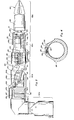
- FIGURE 2 is a side-elevational view of a manipulator arm constructed in accordance with the present invention.
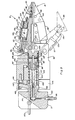
- FIGURE 3 is an enlarged, side-elevational view, partially broken away and in cross section, showing a jaw assembly or terminal device constructed in accordance with the present invention.
- FIGURE 4 is an enlarged end elevational view of the module coupling sleeve shown in Figure 2.
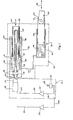
- The basic elements of the electromechanical manipulator assembly of the present invention for achieving a single function or type of movement can be seen in Figure 1. As will become apparent hereinafter, the basic elements of Figure 1 can be duplicated and added together to produce electromechanical arms capable of extremely complex movements.
- Referring to Figure 1, the electromechanical manipulator assembly can be seen to include input means, generally designated 21, preferably comprised of a manually operable,
X-Y input controller 22 electrically coupled to motorcontrol operation amplifier 23, which in turn is connected byconductor 24 toD.C. motor 26. Direct coupling of the electrical motor to a manipulator arm presents substantial shock loading and gearbox design problems. Accordingly, extending from agearbox 27 driven bymotor 26 is anoutput shaft 28 to a hydraulic circuit, generally designated 29. - As used in the remote manipulator assembly of the present invention, the X-Y input device 22 (preferably with a joy stick that is not displaceable) and
operation amplifier 23 are located at the position of the user or operator, whilemotor 26,gearbox 27,shaft 28 andhydraulic circuit 29 are mounted at the manipulator arm. If the apparatus of the present invention is used in a manned submersible, the distance between the operator and the arm is not great, but when the device of the present invention is used in an unmanned, robotic system, the operator, X-Y controller and operation amplifier are typically located at the surface, while the D.C. motor and hydraulic circuit are submerged, as much as several hundred feet. Electrical connector means 24, accordingly, may vary from between 10 to 1000 feet in length. - It is broadly known in the electromechanical manipulator assembly art to employ an electrical input means, such as
controller 22 andD.C. motor 26, in combination with ahydraulic circuit 29 in order to effect displacement of a manipulator arm. Such prior art systems typically employ complex hydraulic valve arrangements and a fluid pump driven by the D.C. motor. In the improved manipulator assembly of the present invention, however, hydraulic circuit means 29 includes a master piston-cylinder assembly, generally designated 32, connected for input frominput shaft 28 and directly hydraulically coupled by a fixed-volume, closed, hydraulic circuit to a slave piston-cylinder assembly, generally designated 33. Such fixed-volume coupling produces direct and proportional displacement of the slave assembly and a mechanical manipulator means, schematically shown as a piston connecting rod generally designated 34, coupled toslave assembly 33. - It is preferable that master piston-
cylinder assembly 32 include acylinder 36 in whichpiston 37 is movably mounted. Movement ofpiston 37 may be accomplished bycoupling drive shaft 28 throughthrust bearings 38 to ascrew 39 which extends into a ball- type offollower assembly 41 carried bysleeve 42 threadably mounted topiston 37. Thepiston 37 is formed with an axial bore 43 dimensioned for receipt ofscrew shaft 39 as the piston is reciprocated, as indicated byarrows 44. - Reciprocation of
piston 37 inmaster cylinder 36 produces displacement ofhydraulic fluid 46 into and out ofconduit 47, which is coupled toslave cylinder 48. Reciprocally mounted inslave cylinder 48 isslave piston 49 to which amanipulator arm element 34 can be secured, for example bypivotal mounting pin 51. The combined volume ofcylinders conduit 47 is fixed and closed. Displacement of the master piston, therefore, produces a directly proportional displacement ofslave piston 49, as indicated byarrows 52. - Rather than enclosing both the master and slave piston-cylinder assemblies so as to isolate the same from the ambient water pressure in which the manipulator arm is operating, it is an important feature of the present invention that both master piston-
cylinder assembly 32 and slave piston-cylinder assembly 33 be formed with surfaces that are positioned for and exposed to the ambient water pressure in which the manipulator assembly is operating. Thus,end surface 53 ofpiston 37 andend surface 54 ofpiston 49 are exposed to the water pressure at the depth at which the manipulator arm is being employed. Thus, there is no pressure differential between the master and slave which must be overcome, as would be the case if, for example, the master cylinder was enclosed. Under no-load conditions, moreover,slave piston 49 is free to move incylinder 48, and the ambient water pressure acting onsurface 54 of the slave piston will drive the piston inwardly until the pressure on thehydraulic fluid 46 inside the closed system is substantially equal to the pressure of the surrounding body of water at the depth of the manipulator arm. - This equilibrium relationship between the hydraulic fluid pressure and the ambient water pressure results in a substantially constant relationship between the torque on
motor 26 and the force applied tomanipulator arm element 34, regardless of the depth of operation (below a certain minimum depth) of the manipulator arm. - Additionally, exposing
surfaces master cylinder 37 is pulled inwardly towardmotor 26 by rotation ofshaft 28,fluid 46 will be forced fromcylinder 36 throughconduit 47 tocylinder 48. This in turn will result in outward displacement ofpiston 49. When themaster piston 37 is moved outwardly away frommotor 26 byshaft 28, the water pressure onsurface 54 ofslave piston 49 immediately pushes the slave piston andarm element 34 inwardly to produce a very positive stroke relationship between the master piston andarm element 34. - As the operating depth at which the hydraulic circuit is positioned decreases, the pressure on
surface 54 tending to return the slave cylinder is reduced. It has been found, however, that even when the apparatus of the present invention is operated above water so that the pressure onsurface 54 is only 14.7 lbs. psi, the slave piston will follow the master piston quite positively and accurately. Thus, the electromechanical manipulator assembly of the present invention can be readily controlled even at very minimum depths. Since much of the undersea use of remote manipulator systems is at depths well below 200 feet, for example, from 600 to 1000 feet, the closed, fixed volume hydraulic circuit of Figure 1 is extremely positive and relatively depth insensitive in its operation. - It is a further important feature of the present invention that the manipulator assembly be formed in a manner which prevents driving of
motor 26 in the reverse direction under loading of the manipulator arm. Thus, a load on areelement 34 should not be capable of overcoming the motor, and preferably should not even load the motor. - In the appartus of the present invention reverse operation is prevented by forming the thrust bearing assembly, comprised of shaft mounted
thrust member 35 andbearings 38, with sufficient friction to prevent reverse operation. The area ofmember 35 mounted for rotation withshaft 28 and the coefficient of friction withbearings 38 have been selected so that the friction force in the bearings is always slightly greater than the torque that can be generated in the ball-screw assembly by loadingarm 34. - An inward force on
arm 34 will pressurize fluid 46 in the master cylinder tending to urgemaster piston 37 outwardly. The outward force onpiston 37 applies a torque to screwelement 39, but also pullsshaft 28 outwardly and urges thrustelement 35 againstbearings 38. The friction betweenthrust element 35 andbearings 38 will be slightly greater that the torque onshaft 28 and rotation of the shaft prevented. As the load onarm 34 increases, the torque increases onshaft 28, but the friction force increases just as fast and always remains slightly higher than the torque. The result is thatthrust bearings 38 lock up the system against reverse running. This action occurs regardless of the directon of axial displacement and prevents reverse running whether the load onelement 34 is positive or negative. - In order to drive the assembly with
motor 26, however, the motor must also overcome the friction force inbearings 38. Thus, motor-gearbox assembly is selected to have sufficient torque output not only to produce the force required atarm 34, but to overcome the friction inthrust bearings 38 at maximum load. Using teflon thrust bearings, slightly more than one-half of the output is required to overcome the thrust bearing, but this requirement can be easily met with appropriate motor and gearbox selection. - A further significant feature of the master ball-screw assembly is that the rotation of
piston 37 is prevented by the friction of O-rings 40 againstpiston 37. Thus, rotation ofscrew 39 is converted into axial displacement ofpiston 37 only if the piston is secured against rotation. This can be done by keying the piston, but it is advantageously accomplished by O-rings 40 which frictionally engage the piston. Moreover, the pressure offluid 46 on the innermost O-rings 40 causes the frictional force to increase with loading. As the tendency ofpiston 37 to rotate increases, therefore, the friction force of O-rings 40 also increases. - The assembly of the present invention, therefore, includes a load-responsive, reverse- operation blocking system and a load-responsive, piston rotation stabilizing system.
- The hydraulic circuit of the present invention produces linear displacement of
piston 37 which is positively and directly controlled in a fixed relationship to the torque ofmotor 26. It is possible, therefore, to employ sensing means (not shown) which feeds back to the operator or user a signal indicating the torque and the speed ofmotor 26. Such feedback can then be used by the manipulator operator to give input toX-Y input device 22 and thereby more accurately and positively control displacement ofmanipulator element 34. The feedback system is based on the ability to positively and substantially linearly relate torque and speed ofmotor 26 to displacement ofmaster piston 37. - The feedback system suitable for use with the electromechanical manipulator assembly of the present invention is more fully set forth in my co-pending patent application entitled, "Apparatus and Method for Providing useful Audio Feedback to Aid in the Operation of Remotely controlled Powered Manipulators".
- Since
hydraulic circuit 29 is a closed and a fixed-volume circuit, the speed of movement ofslave piston 49 and the value or quantity of force and direction of movement are all also positively and directly controlled byelectric motor 26. Therefore, even allowing for slight non-linear electrical and mechanical characteristics of the drive motor and a friction loss of about one-half in the thrust bearings, the input current tomotor 26 is directly porportional to the force exerted on the workpiece bymanipulator element 34. Similarly, the input voltage (after taking into account the torque component of applied voltage) is directly proportional to the speed of movement of themanipulator arm 34. - With the electromechanical manipulator assembly of the present invention, therefore, it is possible to get very smooth and continuous controlled movements ranging in speed and force from 0 to a maximum speed and force, all without steps, discontinuities, or jerking or shuttering motion. Moreoever, the electromechanical system of the present invention is very simple and relatively troublefree in its operation. It does not require complicated solenoid valving, continuously operating pumps, large or complicated gearboxes or elaborate control and sensing feedback apparatus.
- As thus far described, the electromechanical manipulator assembly is constructed to perform one function, for example, displacement of
arm 34 in a positive or negative direction along the X axis, as indicated byarrows 52. In order to provide a manipulator arm capable of complex displacements, it is preferable that arm assembly, generally designated 61 and shown in Figure 2, be composed of a plurality of modules, generally designated 62a, 62b, 62c and 62d, each capable of performing at least one manipulative function. If, for example,arm element 34b is coupled bypin 63 toelement 64 ofmodule 62b, andelement 66 in whichslave cylinder 48b andpiston 49b are mounted is pivoted atpin 67 toelement 64, displacement ofslave piston 49b to the right will cause pivoting of the arm assembly upwardly, while displacement to the left will cause pivoting of the arm assembly downwardly. Displacement in one direction is limited by the bottom of the cylinder, and displacement in the other direction is limited by transverse stops or pins 70 projecting inwardly from the cylinder walls so as to engage the piston. - If the
next module 62c is oriented at 90° toassembly 62b, displacement of theslave piston 49c incylinder 48c to the left will produce pivoting aboutpin 65 of the arm assembly outwardly of the sheet, while displacement ofpiston 49c andarm 34c to the right will cause a pivoting of the arm assembly inwardly from the sheet. The combination ofmodules Module conduits connector 24c andoperation amplifier 23c). This construction will enable simultaneous X-Y movements of manipulator arm assembly 61 by manual input to the input joy stick orlever 25 ofinput device 22. - In addition to providing for linear movement, it is also possible to form one or more of the arm modules for rotational movement. For example,
module 62d can advantageously be formed for rotational movement. Displacement from the fixed volume hydraulic circuit can be communicated throughconduit 47d tomodule 62d from a master piston cylinder assembly. The slave piston cylinder assembly inmodule 62d includes a ball-screw assembly which essentially operates in reverse as compared to master ball-screw assembly 32. This ball-screw assembly is described in more detail hereinafter, but it will cause rotational movement of theterminal body 69 with respect tocollar 71. Usually such units are constructed so that rotational movement in a positive direction of about 110° can be achieved and in a negative direction of about 110°. Greater or lesser rotation can be built intomodule 62d, as may be required by the application to which the manipulator is put. - Each of the
arm modules end 81a formed for mechanical coupling to a matingly-formed member. Each of the modules (except 62d) further has a second end, such as end 82b, similarly formed for mechanical coupling to a matingly-formed member. In the assembly of the present invention,first end 81a is formed for mating coupling to second end 82b in each of the various modules by threadedcollar 86 shown in Figure 4. - In order to enable securement of the modules in any desired angular orientation with respect to each other, the ends are locked in place by a split collar or
sleeve 86 which can be cinched down to lock the modules in place by a plurality ofbolts 87.Bolts 87 pass through threaded longitudinally extendingrods sleeve 86 byflanges 88 which defineslots 89 in which the bolts are positioned. - The remote electromechanical manipulator assembly of the present invention further preferably includes an improved terminal device or jaw means 68, which can best be seen in Figure 3. The jaw assembly includes a pair of opposed jaw means, generally designated 91, formed for gripping of objects or workpieces. At least one of jaw means 91 is movably mounted with respect to the remainder of the jaw means, and drive means, in this case a hydraulic circuit, is coupled through
conduit 95 to displace the moveable one of the jaw means. In the improved manipulator apparatus, the moveable one of jaw means 91 is formed to include a base member or element.92 movably mounted with respect tobody portion 93 of the jaw assembly and atip member 94 pivotally mounted aboutpivot pin 96 to thedistal end 97 ofbase member 92. The hydraulic drive circuit, generally designated 98, is formed and connected to pivotally displacetip 94 toward the other jaw independently ofdisplacement base member 92 toward the other jaw. - This construction enables the articulated
tips 94 to close down around the back side of an object. The claw or jaw assembly of the present invention, therefore, can be used to grip pipes and other round objects with thetips 94 articulating down around the back side of the pipe. - Operation of the jaw assembly so as to cause independent pivoting of the jaw tips can best be understood by a more detailed description of
hydraulic circuit 98.Conduit 95 is coupled at jaw assembly collar orcuff element 71 to supply hydraulic fluid to a conduit orpassageway 102 therein. Mounted in communication withpassageway 102 is apassageway 103 in axially extendingmember 104. Adistribution element 106 is formed with transversely extendingpassageways 107 which communicate fluid to an annular recessedarea 108 and in turn toradial passageways 109. Hydraulic fluid then flows through the center 111 oftransverse pin 112 and out the transverse passageways to the periphery 114 of the pin. Fluid at the periphery 114 of the pin is then able to flow down axially extending passageway 116 inpiston member 117 to a cylinder 118 inbase member 92 of the pivotal jaws. Asecond piston 119 is mounted for reciprocation inauxiliary cylinder 121 which is in fluid communication with primary cylinder 118. The end ofpiston 119 is coupled at 122 to tipmember 94. - When the hydraulic fluid pressure is increased, the pressure in cylinder 118 and
auxiliary cyclinder 121 increases so as to apply pressure topiston 117 andpiston 119. Sincepiston 117 is pinned atpin 112 tobody 93 of the jaw assembly,member 92 tends to rotate aboutpin 123 in a clockwise direction or toward the remaining jaw means 91. Similarly, the pressure onpiston 119 tends to urge that piston to the right, causing pivoting oftip 94 aboutpin 96 in a clockwise direction or toward the remaining jaw means 91. When fluid is removed fromcircuit 98 andcylinders 118 and 121,jaw member 92 tends to be pulled down overpiston 117 or pivoted in a counterclockwise direction away from the remaining jaw to open the jaw assembly.Piston 119 experiences a similar tendency, but theshoulder 124 limits the counterclockwise pivoting so that bothmembers - When a workpiece or object is placed between the jaws,
base member 92 will tend to engage the workpiece first as pressure incylinders 118 and 121 increases. The resistance from the workpiece, however, will soon stop closing ofbase member 92. If the workpiece or object does not engagetip 94, the pressure increase in cylinder 118 andauxiliary cylinder 121 will continue to displacepiston 119, causing the tip to pivot independently ofbase member 92 aboutpin 96. This pivoting can be seen in phantom in connection with lower jaw 91 and results in thetip 94 pivoting down around the back side of the object until resistance is met. The claw structure is, therefore, substantially equivalent to a knuckle construction which allows the claw or jaw means to partially encircle round objects, such as pipes of the type often employed in underwater oil exploration and development. - It is an important feature of the jaw construction that the pressure applied by
jaw members end surface 126 ofpiston 117 is much greater than the area ofsurface 127 ofpiston 119. The gripping force induced bypiston 119 inelement 94 produces a reacton force about not only pivotpin 96, but also aboutpivot pin 123. Thus, the gripping force intip element 94 subtracts from the gripping force inelement 92. In order to have substantially the same gripping force along the jaws,piston 119 is about one-half the area ofpiston 126. - In order to insure that
tip element 94 does not start to close or pivot aboutpin 96 beforeelement 92 starts pivoting aboutpin 123, O-ring 131 preferably has greater friction incylinder 121 than does 0-ring 132 in cylinder 118. - As is shown in the drawing, it is preferable that both of jaw means 91 be formed with independently movable tips and movable base members which work off of a common
hydraulic circuit 98. Such a common hydraulic circuit also has the advantage of causing the jaw means which is not engaged with the object to continue to close, while a jaw means which is engaging and being resisted by an object does not move. If, for example, the arm assembly is used to grip a pipe and the top jaw- means 91 engages the top surface of the pipe first, the bottom jaw means 91 will not stop, but continues upwardly until it engages the bottom surface of the pipe. In both cases, the jaw tips knuckle around the back side of the pipe. - As will be appreciated, the jaw assembly of the present invention can be driven by a linear ball-screw type master piston and cylinder as above described with
hydraulic circuit 98 being comprised of a closed, fixed volume hydraulic circuit coupled to slave piston andcylinder assemblies - Rotation of terminal unit or
jaws 68 is accomplished by hydraulic pressure inconduit 47d, which is coupled tocuff 71 andpassageway 141 formed therein. Fluid is discharged frompassageway 141 intospace 142 between cuff orcollar portion 143 andcylinder defining member 144. Mounted about the periphery ofcollar portion 143 is 0-ring 146 which sealsspace 142 to permit pressurizing of the same with hydraulic fluid. Also fixedly threaded into collar orcuff 71 ismember 104 which is formed with a helical path ofrecess 147. - The
assembly body 93 is mounted to a nut or follower member 148 which carriesball bearings 149 to provide, with helically threadedelement 104, a screw- ball assembly similar to that shown in Figure 1. As pressure builds in space orcylinder 142, the nut or follower 148 rotates aboutscrew element 104 to cause rotation of the claw or terminal device. Withdrawing fluid fromspace 142 produces rotation in an opposite direction, since the back side ofcollar portion 142 is subject to the ambient pressure. Rotation is limited byshoulder 151 in one direction and bycollar portion 142 in the opposite direction. - Although not shown in Figure 2, the master cylinders for the various modules and
terminal unit 68 are preferably located proximate the base of manipulator assembly, and as indicated above they are each exposed to the same ambient pressure as are the slave pistons.
Claims (28)
said master piston-cylinder assembly (32) is also formed with an ambient pressure surface (53) coupled to pressurize hydraulic fluid in said closed hydraulic circuit (29) in response to liquid pressure against said surface on said master piston-cylinder assembly (32), and both said master piston-cylinder assembly (32) and said slave piston-cylinder assembly (33) are positioned in said manipulator assembly for operation while submerged in said liquid.
said master piston-cylinder assembly (32) and said slave piston-cylinder assembly (33) are both positioned proximate said mechanical manipulator means (34).
said electrically powered input means (21) includes a direct current motor (26) and controller means (22) coupled to said motor, said controller means (22) being positioned in said manipulator assembly relatively remote of said mechanical manipulator means (34).
said motor (26) is mounted in said manipulator assembly proximate said master piston-cylinder assembly (32).
said slave assembly (33) is formed to cause rotation of said manipulator assembly.
means (35, 38) for preventing reverse displacement of said master assembly (32) under loading of said slave assembly (33).
said master assembly (32) includes means (40) formed to prevent rotation of the axially movable element (37) of said master assembly (32) during rotation of said ball-screw assembly (39, 41).
said means formed to prevent rotation of said axially movable element is provided as 0-ring means (40) positioned to be exposed to pressure in the cylinder portion (36) of said master assembly (32) and formed for sufficient frictional engagement with said axially movable element (37) to prevent rotation thereof for substantially all pressures in said cylinder portion (36).
said drive means (95) is provided by a fluid drive assembly, said drive assembly including a common cylinder (118) and a pair of piston members (117, 119) mounted in fluid communication with said cylinder (118), one of said piston members (117) being mounted and connected to displace said base member (92), and a remainder of said piston members (119) being mounted and connected to displace said tip member (94).
the pistons (119) coupled to said tip members (94) have an area in communication with said cylinders (118) which is about one-half the area of the pistons (117) coupled to said base members (92).
said jaw assembly includes jaw elements (91) and means (141, 147, 149) for rotating said jaw elements (91) with respect to the longitudinal axis of said arm assembly (61).
said first ends (81a) and said second ends (81b) are formed with thread means; and
collar means (86) formed for locking said ends (81a, 81b) together in any one of a plurality of selected angularly rotated positions about the longitudinal axis of said arm assembly (61).
said displacement means is provided by a hydraulic cylinder (48, 48c) and piston (49b, 49c) coupled by conduit means (47b, 47c) to said drive means (32), a movable one (49b, 49c) of said cylinder (48, 48c) and piston (49b, 49c) being exposed to ambient underwater pressure over a surface (54) thereof to cause pressurization of fluid in said cylinder (48, 48c).
said drive means (32) includes a master piston (37) and cylinder (36) with a movable one (37) of said master piston (37) and cylinder (36) being exposed to ambient underwater pressure, said master piston (37) and cylinder (36) being located at about the same depth underwater as said arm portions (61), and said master piston (37) and cylinder (36), said conduit (47b, 47c) and said piston (49b, 49c) and cylinder (48, 48c) in said arm portion (61) forming a fixed volume, closed hydraulic circuit (29).
Priority Applications (1)
| Application Number | Priority Date | Filing Date | Title |
|---|---|---|---|
| AT83303065T ATE31393T1 (en) | 1983-02-15 | 1983-05-27 | ELECTROMECHANICAL HANDLING DEVICE. |
Applications Claiming Priority (2)
| Application Number | Priority Date | Filing Date | Title |
|---|---|---|---|
| US06/466,606 US4607998A (en) | 1983-02-15 | 1983-02-15 | Electromechanical manipulator assembly |
| US466606 | 1983-02-15 |
Publications (3)
| Publication Number | Publication Date |
|---|---|
| EP0120156A2 true EP0120156A2 (en) | 1984-10-03 |
| EP0120156A3 EP0120156A3 (en) | 1984-12-19 |
| EP0120156B1 EP0120156B1 (en) | 1987-12-16 |
Family
ID=23852411
Family Applications (1)
| Application Number | Title | Priority Date | Filing Date |
|---|---|---|---|
| EP83303065A Expired EP0120156B1 (en) | 1983-02-15 | 1983-05-27 | Electromechanical manipulator assembly |
Country Status (6)
| Country | Link |
|---|---|
| US (1) | US4607998A (en) |
| EP (1) | EP0120156B1 (en) |
| JP (1) | JPS59152086A (en) |
| AT (1) | ATE31393T1 (en) |
| DE (1) | DE3374922D1 (en) |
| NO (1) | NO832252L (en) |
Families Citing this family (19)
| Publication number | Priority date | Publication date | Assignee | Title |
|---|---|---|---|---|
| FR2565882B2 (en) * | 1984-06-13 | 1987-09-18 | Centre Nat Rech Scient | CONNECTION DEVICE WITH MULTIPLE DEGREES OF FREEDOM |
| AT391827B (en) * | 1984-12-07 | 1990-12-10 | Sticht Walter | HANDLING DEVICE FOR ASSEMBLY PARTS |
| JPS61265283A (en) * | 1985-05-17 | 1986-11-25 | 株式会社 成茂科学器械研究所 | Manipulator for glass electrode,etc. |
| IT207929Z2 (en) * | 1986-02-21 | 1988-02-22 | Roltra Spa | SERVO-ASSISTED BRAKE SYSTEM FOR VEHICLES |
| US4918921A (en) * | 1987-10-22 | 1990-04-24 | Automotive Products Plc | Coaxial push rod and hollow screw ball nut drive for master cylinder |
| DE59202094D1 (en) * | 1991-01-14 | 1995-06-08 | Engel Gmbh Maschbau | DEVICE FOR CARRYING OUT A TWO-STAGE LINEAR MOVEMENT. |
| US5287700A (en) * | 1992-10-14 | 1994-02-22 | Mcdonnell Douglas Helicopter Company | Flexible bellows actuation system |
| US5310257A (en) * | 1992-10-29 | 1994-05-10 | Fluid Management Limited Partnership | Mixing apparatus |
| US5305917A (en) * | 1992-11-19 | 1994-04-26 | Fluid Management Limited Partnership | Simultaneous dispensing apparatus |
| US5407100A (en) * | 1994-01-07 | 1995-04-18 | Fluid Management Limited Partnership | Dispensing apparatus with a moveable plate |
| JP3331152B2 (en) * | 1997-07-29 | 2002-10-07 | 東芝機械株式会社 | Closed hydraulic pressure booster |
| IT1306514B1 (en) * | 1998-08-05 | 2001-06-11 | Vincenzo Arrichiello | BELLOW ACTUATION DEVICE, ESPECIALLY FOR ROTARY MANIPULATOR, AND METHOD OF DRIVING THAT DEVICE. |
| US6352018B1 (en) | 2000-04-20 | 2002-03-05 | Spicer Technology, Inc. | Hydraulic actuator assembly with integral damper/accumulator |
| TW577504U (en) * | 2002-11-27 | 2004-02-21 | Bekaltek Sdn Bhd | Mounting assembly for container valve shut-off device |
| JPWO2006120765A1 (en) * | 2005-05-09 | 2008-12-18 | 株式会社ファルコム | Pressurizing device |
| US7967354B2 (en) * | 2008-05-06 | 2011-06-28 | Fanuc Robotics America, Inc. | Mixed size product handling end of arm tool |
| US10156245B2 (en) | 2016-02-22 | 2018-12-18 | Lockheed Martin Corporation | High-precision hydraulic actuator |
| US10286565B1 (en) | 2016-06-13 | 2019-05-14 | Amazon Technologies, Inc. | Skin replacement for robotic manipulator |
| US9975256B1 (en) * | 2016-06-13 | 2018-05-22 | Amazon Technologies, Inc. | Robotic gripper with digits controlled by shared fluid volume |
Citations (5)
| Publication number | Priority date | Publication date | Assignee | Title |
|---|---|---|---|---|
| FR1233754A (en) * | 1958-11-05 | 1960-10-12 | Electricite Ind Belge L | Hydraulic control device |
| US3454169A (en) * | 1967-07-20 | 1969-07-08 | Robert H Bridges | Remote control submersible and/or remote manipulator arm |
| DE2040001A1 (en) * | 1970-08-12 | 1972-02-17 | Hanning Elektro Werke | Electromotive spindle adjustment device |
| DE2330393A1 (en) * | 1973-06-15 | 1975-01-02 | Bruker Physik Ag | Mechanically operated manipulator for submarines - has mechanical hand mounted on jointed arm based on human arm |
| FR2271900A1 (en) * | 1974-05-22 | 1975-12-19 | Supemec Sa | Machine tool workpiece feed device - has cam actuating transfer carriage via lever and two coupled rams |
Family Cites Families (4)
| Publication number | Priority date | Publication date | Assignee | Title |
|---|---|---|---|---|
| AT208743B (en) * | 1958-10-14 | 1960-04-25 | Rudolf A Dipl Ing Binder | Emergency brake for motor vehicles with hydraulic pressure brakes |
| US3422965A (en) * | 1967-02-13 | 1969-01-21 | Westinghouse Electric Corp | Manipulator apparatus |
| US3440825A (en) * | 1967-04-06 | 1969-04-29 | Westinghouse Electric Corp | Hydraulic undersea manipulator apparatus |
| US3835750A (en) * | 1973-05-14 | 1974-09-17 | Unimation Inc | Record-playback manipulator system utilizing hydraulic microbit actuators |
-
1983
- 1983-02-15 US US06/466,606 patent/US4607998A/en not_active Expired - Fee Related
- 1983-05-27 EP EP83303065A patent/EP0120156B1/en not_active Expired
- 1983-05-27 DE DE8383303065T patent/DE3374922D1/en not_active Expired
- 1983-05-27 AT AT83303065T patent/ATE31393T1/en not_active IP Right Cessation
- 1983-06-21 NO NO832252A patent/NO832252L/en unknown
- 1983-06-22 JP JP58111111A patent/JPS59152086A/en active Pending
Patent Citations (5)
| Publication number | Priority date | Publication date | Assignee | Title |
|---|---|---|---|---|
| FR1233754A (en) * | 1958-11-05 | 1960-10-12 | Electricite Ind Belge L | Hydraulic control device |
| US3454169A (en) * | 1967-07-20 | 1969-07-08 | Robert H Bridges | Remote control submersible and/or remote manipulator arm |
| DE2040001A1 (en) * | 1970-08-12 | 1972-02-17 | Hanning Elektro Werke | Electromotive spindle adjustment device |
| DE2330393A1 (en) * | 1973-06-15 | 1975-01-02 | Bruker Physik Ag | Mechanically operated manipulator for submarines - has mechanical hand mounted on jointed arm based on human arm |
| FR2271900A1 (en) * | 1974-05-22 | 1975-12-19 | Supemec Sa | Machine tool workpiece feed device - has cam actuating transfer carriage via lever and two coupled rams |
Also Published As
| Publication number | Publication date |
|---|---|
| US4607998A (en) | 1986-08-26 |
| DE3374922D1 (en) | 1988-01-28 |
| JPS59152086A (en) | 1984-08-30 |
| ATE31393T1 (en) | 1988-01-15 |
| NO832252L (en) | 1984-08-16 |
| EP0120156A3 (en) | 1984-12-19 |
| EP0120156B1 (en) | 1987-12-16 |
Similar Documents
| Publication | Publication Date | Title |
|---|---|---|
| US4607998A (en) | Electromechanical manipulator assembly | |
| US4648782A (en) | Underwater manipulator system | |
| US4188166A (en) | Small size telemanipulator | |
| US4666362A (en) | Parallel link manipulators | |
| US3904042A (en) | Manipulator apparatus | |
| US5410944A (en) | Telescoping robot arm with spherical joints | |
| EP2383422B1 (en) | Work string controller | |
| US2861699A (en) | Method and apparatus for performing operations at a remote point | |
| US4367998A (en) | Manipulators | |
| Todd | Fundamentals of robot technology: An introduction to industrial robots, teleoperators and robot vehicles | |
| US4938109A (en) | Torque hold system and method | |
| US4190081A (en) | Electro-hydraulic systems | |
| US5039254A (en) | Passive grabbing apparatus having six degrees of freedom and single command control | |
| US3916701A (en) | Rotary wrist actuator for industrial robots | |
| CA2365482C (en) | Apparatus and method for actuating arms | |
| EP0149806B1 (en) | Robotic apparatus with improved positioning accuracy | |
| US4733895A (en) | Electromechanical manipulator assembly | |
| US4575313A (en) | Digital pressure controller | |
| US5000649A (en) | Electromechanical manipulator assembly | |
| US3683747A (en) | Manipulator and manipulator control system | |
| US4630688A (en) | Power spinner for rotating a kelly joint | |
| CN208057553U (en) | A kind of mechanical electronic hydraulic digital servo valve | |
| Zhang et al. | 7000M pressure experiment of a deep-sea hydraulic manipulator system | |
| GB2596546A (en) | Manipulation module | |
| EP3865256A1 (en) | Subsea manipulator |
Legal Events
| Date | Code | Title | Description |
|---|---|---|---|
| PUAI | Public reference made under article 153(3) epc to a published international application that has entered the european phase |
Free format text: ORIGINAL CODE: 0009012 |
|
| AK | Designated contracting states |
Designated state(s): AT BE CH DE FR GB IT LI LU NL SE |
|
| PUAL | Search report despatched |
Free format text: ORIGINAL CODE: 0009013 |
|
| AK | Designated contracting states |
Designated state(s): AT BE CH DE FR GB IT LI LU NL SE |
|
| 17P | Request for examination filed |
Effective date: 19850611 |
|
| 17Q | First examination report despatched |
Effective date: 19860605 |
|
| GRAA | (expected) grant |
Free format text: ORIGINAL CODE: 0009210 |
|
| AK | Designated contracting states |
Kind code of ref document: B1 Designated state(s): AT BE CH DE FR GB IT LI LU NL SE |
|
| REF | Corresponds to: |
Ref document number: 31393 Country of ref document: AT Date of ref document: 19880115 Kind code of ref document: T |
|
| RBV | Designated contracting states (corrected) |
Designated state(s): GB |
|
| REF | Corresponds to: |
Ref document number: 3374922 Country of ref document: DE Date of ref document: 19880128 |
|
| EN | Fr: translation not filed | ||
| PG25 | Lapsed in a contracting state [announced via postgrant information from national office to epo] |
Ref country code: GB Effective date: 19880527 |
|
| PLBE | No opposition filed within time limit |
Free format text: ORIGINAL CODE: 0009261 |
|
| STAA | Information on the status of an ep patent application or granted ep patent |
Free format text: STATUS: NO OPPOSITION FILED WITHIN TIME LIMIT |
|
| 26N | No opposition filed | ||
| GBPC | Gb: european patent ceased through non-payment of renewal fee |