EP0120006B1 - Flammwidriges hydraulisches zweifluid-system - Google Patents
Flammwidriges hydraulisches zweifluid-system Download PDFInfo
- Publication number
- EP0120006B1 EP0120006B1 EP83900085A EP83900085A EP0120006B1 EP 0120006 B1 EP0120006 B1 EP 0120006B1 EP 83900085 A EP83900085 A EP 83900085A EP 83900085 A EP83900085 A EP 83900085A EP 0120006 B1 EP0120006 B1 EP 0120006B1
- Authority
- EP
- European Patent Office
- Prior art keywords
- piston
- hydraulic fluid
- pressure
- housing
- chamber
- Prior art date
- Legal status (The legal status is an assumption and is not a legal conclusion. Google has not performed a legal analysis and makes no representation as to the accuracy of the status listed.)
- Expired
Links
Images


Classifications
-
- B—PERFORMING OPERATIONS; TRANSPORTING
- B60—VEHICLES IN GENERAL
- B60T—VEHICLE BRAKE CONTROL SYSTEMS OR PARTS THEREOF; BRAKE CONTROL SYSTEMS OR PARTS THEREOF, IN GENERAL; ARRANGEMENT OF BRAKING ELEMENTS ON VEHICLES IN GENERAL; PORTABLE DEVICES FOR PREVENTING UNWANTED MOVEMENT OF VEHICLES; VEHICLE MODIFICATIONS TO FACILITATE COOLING OF BRAKES
- B60T8/00—Arrangements for adjusting wheel-braking force to meet varying vehicular or ground-surface conditions, e.g. limiting or varying distribution of braking force
- B60T8/32—Arrangements for adjusting wheel-braking force to meet varying vehicular or ground-surface conditions, e.g. limiting or varying distribution of braking force responsive to a speed condition, e.g. acceleration or deceleration
- B60T8/321—Arrangements for adjusting wheel-braking force to meet varying vehicular or ground-surface conditions, e.g. limiting or varying distribution of braking force responsive to a speed condition, e.g. acceleration or deceleration deceleration
- B60T8/325—Systems specially adapted for aircraft
-
- B—PERFORMING OPERATIONS; TRANSPORTING
- B60—VEHICLES IN GENERAL
- B60T—VEHICLE BRAKE CONTROL SYSTEMS OR PARTS THEREOF; BRAKE CONTROL SYSTEMS OR PARTS THEREOF, IN GENERAL; ARRANGEMENT OF BRAKING ELEMENTS ON VEHICLES IN GENERAL; PORTABLE DEVICES FOR PREVENTING UNWANTED MOVEMENT OF VEHICLES; VEHICLE MODIFICATIONS TO FACILITATE COOLING OF BRAKES
- B60T13/00—Transmitting braking action from initiating means to ultimate brake actuator with power assistance or drive; Brake systems incorporating such transmitting means, e.g. air-pressure brake systems
- B60T13/10—Transmitting braking action from initiating means to ultimate brake actuator with power assistance or drive; Brake systems incorporating such transmitting means, e.g. air-pressure brake systems with fluid assistance, drive, or release
- B60T13/12—Transmitting braking action from initiating means to ultimate brake actuator with power assistance or drive; Brake systems incorporating such transmitting means, e.g. air-pressure brake systems with fluid assistance, drive, or release the fluid being liquid
-
- B—PERFORMING OPERATIONS; TRANSPORTING
- B60—VEHICLES IN GENERAL
- B60T—VEHICLE BRAKE CONTROL SYSTEMS OR PARTS THEREOF; BRAKE CONTROL SYSTEMS OR PARTS THEREOF, IN GENERAL; ARRANGEMENT OF BRAKING ELEMENTS ON VEHICLES IN GENERAL; PORTABLE DEVICES FOR PREVENTING UNWANTED MOVEMENT OF VEHICLES; VEHICLE MODIFICATIONS TO FACILITATE COOLING OF BRAKES
- B60T17/00—Component parts, details, or accessories of power brake systems not covered by groups B60T8/00, B60T13/00 or B60T15/00, or presenting other characteristic features
- B60T17/18—Safety devices; Monitoring
-
- B—PERFORMING OPERATIONS; TRANSPORTING
- B64—AIRCRAFT; AVIATION; COSMONAUTICS
- B64C—AEROPLANES; HELICOPTERS
- B64C25/00—Alighting gear
- B64C25/32—Alighting gear characterised by elements which contact the ground or similar surface
- B64C25/42—Arrangement or adaptation of brakes
-
- F—MECHANICAL ENGINEERING; LIGHTING; HEATING; WEAPONS; BLASTING
- F16—ENGINEERING ELEMENTS AND UNITS; GENERAL MEASURES FOR PRODUCING AND MAINTAINING EFFECTIVE FUNCTIONING OF MACHINES OR INSTALLATIONS; THERMAL INSULATION IN GENERAL
- F16D—COUPLINGS FOR TRANSMITTING ROTATION; CLUTCHES; BRAKES
- F16D2125/00—Components of actuators
- F16D2125/02—Fluid-pressure mechanisms
- F16D2125/026—Pressure-to-pressure converters, e.g. hydropneumatic
Definitions
- the present invention relates to hydraulic systems for aircraft and the like, such as aircraft ground wheel braking systems, e.g. the prior art aircraft ground wheel braking system of Figs. 1-4 of the drawings, which corresponds to the preamble of claim 1.
- aircraft ground wheel braking systems e.g. the prior art aircraft ground wheel braking system of Figs. 1-4 of the drawings, which corresponds to the preamble of claim 1.
- the Air Force has become increasingly concerned about the danger and dollar loss caused by aircraft hydraulic fires originating in a braking system of the kind referred to.
- the Air Force experienced approximately 153 noncombat hydraulic fires with an associated dollar loss of over 179 million.
- a major cause of these fires is the ignition of hydraulic fluid on hot surfaces.
- about sixty-three percent of the hydraulic fluid fires occurred in the wheel well and/or landing gear area. Most of these fires were related to the ignition of hydraulic fluid on hot brakes.
- the hydraulic fluid currently used on most military aircraft is a petroleum-based mineral fluid, per military specification MIL-H-5606, which has a low manifold ignition temperature and high heat of combustion, and burns quite readily.
- MIL-H-83282 is being used because of its gunfire resistance and somewhat lower overall flammability characteristics. However, it also has a relatively low hot-surface ignition temperature.
- CTFE chlorotrifluoroethylene
- CTFE fluid in aircraft hydraulic systems would greatly alleviate fire danger and result in a significant improvement in aircraft safety.
- replacing MIL-H-5606 fluid with CTFE fluid throughout the entire aircraft hydraulic system would result in a significant weight penalty due to the increase in fluid density (e.g., +1700 Ibs for the YC-14 advanced medium STOL cargo aircraft).
- This weight penalty can be reduced to approximately 64 Ibs for a cargo/ transport aircraft and 30 Ibs for a fighter aircraft by employing the two-fluid nonflammable brake hydraulic system of the present invention in which the heavy CTFE fluid is used only in the hydraulic lines to the wheel brakes.
- a first hydraulic fluid which is relatively flammable but otherwise desirable, is used in the system upstream of a piston in a pressure transmitter which serves to mechanically separate the two fluids.
- a relatively nonflammable second hydraulic fluid having characteristics making it undesirable as a single fluid in the system, is used in the system between the isolator piston and an actuator which is in use adjacent a load which produces a considerable amount of heat.
- An example of such a load is the friction surfaces of an aircraft ground wheel brake.
- makeup nonflammable hydraulic fluid is introduced into the system between the piston and the actuator whenever the quantity of such fluid drops below a predetermined value.
- a preferred replenish system comprises a reservoir and means for delivering the hydraulic fluid from the reservoir into the system when needed.
- the system may include a replenish valve which is adapted to open in response to a need for additional second hydraulic fluid in the system.
- the replenish reservoir may comprise a housing and a follower in the housing dividing the housing into a reservoir chamber for the second hydraulic fluid on one side of the follower and a feed pressure chamber on the opposite side of the follower.
- system pressure supplied by the first hydraulic fluid, is introduced into the feed pressure chamber at the same time that it is applied against the piston, and replenishment occurs during operation of the actuator. In a braking system, this would occur whenever (1) the brakes are applied and (2) there is a need to replenish the second hydraulic fluid portion of the actuator system.
- the mechanical divider between the two hydraulic fluids also performs a deboost function.
- Yet another aspect of the invention relates to a construction of the mechanical isolator which permits the use of two different types of seals.
- a first seal constructed from a material which is compatible with the first hydraulic fluid is used to seal between the pressure transmitter piston and its surrounding portion of the pressure transmitter housing.
- a second seal constructed from a second material that is compatible with the second hydraulic fluid is used to seal between the pressure transmitter piston and its surrounding portion of the housing.
- an air chamber is provided in the housing between the two seals so that, if any leakage occurs through either one or both of the seals, the leakage will be into the air chamber.
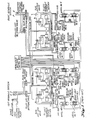
- FIGs. 1-4 An example of an existing aircraft ground wheel braking system is shown by Figs. 1-4.
- a system of this type is used in the KC-135 military tanker/transport aircraft.
- This particular aircraft employs a truck-type main landing gear with paired-wheel brake control. That is, the brake pressure associated with each forward and aft wheel pair on one side of the truck is controlled by a single antiskid valve and control system.
- Fig. 1 is a schematic diagram of the entire system.
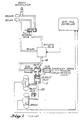
- Fig. 2 is a schematic diagram of only that portion of the system which is associated with a single tandem-wheel pair.
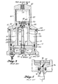
- the prior art system includes a mechanism 10 which is termed a "deboost valve". It comprises a differential housing 12 containing a differential piston 14. Specifically, housing 12 comprises a relatively small first-end portion 16 and a larger second-end portion 18. Housing portion 16 defines a chamber 20 in which a small-diameter portion 22 of the piston reciprocates. Housing portion 18 defines a larger chamber 24 in which the larger second-end portion 26 of piston 14 reciprocates.
- the piston 14 includes a shoulder 28 defined where the small and large-diameter portions of the piston 14 meet. Housing 12 includes a shoulder 30 formed where the small and large-diameter portions 16, 18 of the housing 12 meet.
- a variable-volume chamber 32 is defined axially between the two shoulders 28, 30 and radially between piston portion 14 and housing portion 18. This space 32 is vented to the atmosphere via a vent 34, so that the air in it will not be trapped and retard the movement of piston 14.
- the small-diameter end of piston 14 is formed to include an axial opening in which a replenish valve 36 is situated. This valve includes an axial passageway 38 leading to a valve seat 40 (Fig. 4).
- a ball closure member 42 is normally held into a seated position by fluid within chamber 20.
- the piston 14 is hollow.
- a central orifice 44 provides a way of communicating passageway 38 with the interior 46 of piston 14.
- conduit 48 is connected to the first end 50 of the housing 12. Hydraulic fluid from conduit 48 flows into and out from chamber 20 via an end opening 52.
- End cap 54 comprises a central opening 56 which is communication with a conduit 58 which connects the second end of deboost valve 10 with the wheel brakes (Figs. 1 and 2).
- a plurality of ports 60 communicate the interior 46 of piston 14 with passageway 56.
- a central replenish pin 62 is secured at its base end 64 to a central portion 66 of end cap 54. The opposite end of replenish pin 62 is aligned with orifice 44.
- the KC-135 aircraft employs MIL-H-5606 hydraulic fluid on both sides of the piston 14.
- the piston 14 is provided to perform a deboost function.
- the system pressure upstream of piston 14 is relatively high, e.g. approximately 3,000 psi.
- the differential piston 14 reduces this pressure in that portion of the system between the piston 14 and the wheel brake.
- the area ratio of piston 14 is approximately three-to-one.
- the ball member 42 remains seated and closes the orifice 44 during movement of the piston 14 between the position shown by Fig. 3 and any other position in which piston 14 is located closer to end wall 50. However, whenever piston 14 moves towards end cap 54 beyond the position shown by Fig. 3, the upper end of pin 62 will contact and hold valve ball 42 in position. The valve seat will be moved away from ball 42. This will open the orifice 44 and will allow hydraulic fluid in chamber 20 to flow through the orifice 44 into the space 46. Such fluid will continue to flow until a pressure build-up which occurs on the brake side of the piston 14 causes movement of the piston 14 back into the position shown in Fig. 3. When this happens, ball 42 will again become seated and will close the orifice 44. In this manner, a proper amount of hydraulic fluid is maintained in the system between the piston 14 and the hydraulic brakes.
- the two-fluid concept of the present invention utilizes the deboost device's ability to function as an isolator for the two fluids.
- the pressure transmitter 68 may be composed of many components of the deboost device 10.
- the housings 70 and 12 are identical, and the pistons 72 and 14 are identical.
- the replenishment valve 36 has been replaced by a plug 74.
- the old end cap 54 and the replenish pin 62 have been replaced by a new end cap 76 and a stand pipe 78.
- the standard hydraulic fluid e.g. MIL-H-5606
- the nonflammable hydraulic fluid e.g. CTFE, is used between the piston 72 and the brake or other actuator, depending upon the use to which the system is put.
- the small-area end portion 80 of piston 72 carries an O-ring or other elastomer seal 82 within a circumferential groove.
- a seal material is used which is compatible with the hydraulic fluid within chamber 84.
- a Buna N Nitrile seal can be used when MIL-H-5606 fluid is used within chamber 84.
- a similar O-ring or other elastomer seal 86 is carried within a circumferential groove formed in the large area end of the piston 72.
- the material used for seal 86 is compatible with the hydraulic fluid which exists within the inner space 88 of piston 72.
- the same material is used for seals 90 and 92.
- phosphonitrilic fluoroelastomer (PNF) marketed by the Firestone Company, is the best material found for 0-rings and other elastomer seals intended for use in the region of the CTFE fluid. As in the system shown by Fig.
- the region 94 which is defined axially between piston shoulder 96 and housing shoulder 98 and radially between piston 72 and housing 70, is an air space and is preferably vented to the atmosphere via vent passageways 100.
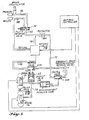
- Each tandem-wheel pair has its own nonflammable hydraulic fluid replenishment system (Fig. 5).
- the schematic diagram for the entire brake system would look very much like the system disclosed by Fig. 1, but modified in accordance with the changes shown in Fig. 5, for each tandem-wheel pair.
- the replenish system comprises a replenish vale 102 which is incorporated in the end cap 76.
- Valve 102 includes a housing 104 having an inner end which is received within an axial opening 106 provided in end cap 76. The outer end of housing 104 is connected to a conduit 108 which is interconnected between valve 102 and a reservoir for additional nonflammable hydraulic fluid.
- Valve 102 includes a valve seat at 110.
- a ball type closure element 112 is normally seated against valve seat 110 by a spring 114.
- a poppet element 116 is positioned inwardly of ball element 112. It includes a first-end portion 118 which extends towards piston 72, a second-end portion 120 which extends towards ball element 112, and a flange 122 between the two end portions 118 and 120.
- a spring 124 positioned between flange 122 and an internal shoulder 126 within valve 102, normally biases the poppet 116 towards the piston 72 and away from the ball element 112.
- the reservoir 128 for additional nonflammable hydraulic fluid may comprise a cylindrical housing 130 having an end cap 132 at one of its ends and an end cap 134 at its opposite end.
- a piston type follower 136 is positioned within the interior of housing 130. It includes a radial end wall 138 and a cylindrical sidewall 140.
- a high-pressure seal 142 is located within a first circumferential groove formed in the sidewall of housing 130.
- a second lower-pressure seal 144 may be provided in a second circumferential groove formed in the sidewall 130.
- a third seal 146 may be formed in a third circumferential groove formed in sidewall 130.
- seal 142 which is located closest to this chamber 148 is a high-pressure seal and is made from a material that is compatible with the particular hydraulic fluid which is stored in chamber 148.
- the seal material for seal 142 is the same material that is used in device 68 for seal 86, i.e. Firestone phosphonitrilic fluoroelastomer (PNF).
- the center seal 144 may be made out of the same material.
- Seat 146 which is positioned closest to end cap 134 is constructed from a material which is compatible with the particular pressure fluid that is introduced into chamber 150.
- MIL-H-5606 fluid is introduced into chamber 150 and the seal material used for seal 146 is the same material that is used in device 68 for seal 82, i.e. Buna N Nitrile.
- Seal 142 should, by itself, provide against leakage from chamber 148 towards seal 146. However, should leakage occur, an annular groove formed in the sidewall 130 collects the leakage and directs it to vent holes 152. In similar fashion, should leakage occur from chamber 150 across seal 146, the fluid would be collected by an annular groove formed in sidewall 130 between seal 146 and seal 144, and from such groove would be directed to a vent opening 154. The presence of seal 144 between the two annular grooves provides additional safeguard against leakage.
- the reservoir 128 is provided with a sight gauge 156 which is provided for indicating the quantity of fluid within chamber 148.
- the particular sight gauge that is illustrated comprises a tubular housing 158 which is mounted at its inner end to end cap 134. Housing 158 is axially directed and receives an axially extending indicator rod 160 which is connected at its inner end to follower end wall 138. Housing 158 need be formed to include a viewing port or window 162.
- the outer end portion 164 of rod 160 may be colored a bright color, such as red, and/or may be marked with indicia as the word "service".
- the rod 160 is moved to the left (as pictured) bringing the end portion 164 into registry with the window 162.
- a suitable seal 166 is provided to seal between end cap 134 and rod 160.
- Each reservoir end cap, 132 and 134 contains two ports.
- End cap 134 includes a port 168 which is connected to a line 170 which supplied a pressure feed fluid.
- the second port receives a bleed valve 172.
- End cap 132 includes a fill port 174, in which a fill valve 176 is received, and an outlet port 178.
- the second end of conduit 108 is connected to the port 178.
- a bleed port 184 is provided in end cap 134.
- the chamber 148 is sized to account for volumetric changes due to temperature, brake wear, and normal fluid loss by leakage.
- the pressure fluid that is introduced into chamber 150 for pressure feeding additional relatively nonflammable fluid into the system is the same fluid that is used in the system on the control side of pressure transmitter 68, i.e. the relatively flammable fluid.
- the system that is shown includes a first conduit 186 which is at supply pressure.
- This conduit and a return conduit 188 are connected to a three-way pilot- controlled metering valve 190.
- the third conduit that is connected to valve 190 extends to the inlet of pressure transmitter 68.
- This conduit 192 includes an antiskid valve 193 which forms no part of the present invention.
- the antiskid valve 193 is shown in schematic form in Fig. 1.
- the fourth conduit of the system is conduit 194 which connects the brake side of pressure transmitter 68 with the wheel brakes 196.
- This conduit 194 may include a conventional pressure relief valve 198.
- Conduit 108 which extends between reservoir chamber 148 and the brake side of piston 72 is a fifth conduit in the system.
- Conduit 170 is a sixth conduit in the system. It is innercon- nected between conduit 192 and the feed pressure inlet 168 for the replenish reservoir 128.
- Conduit 170 includes a restrictor 200.
- conduit 192 The pressure within conduit 192 will be herein referred to as pilot metered pressure. This pressure is supplied to conduit 170 through restrictor 200 for the purpose of eliminating the dynamic effect which the addition of fluid from conduit 192 into chamber 150 would have upon the response and performance of the control system.
- pilot metered pressure to feed additional relatively nonflammable second fluid into the system when needed eliminates the need for a high-pressure air-charged accumulator for performing the replenish function.
- the use of such an accumulator would cause the brakes to lock if leakage occurred through the replenish valve 102.
- the reservoir chamber 148 is pressurized and replenishment occurs only when braking is commanded.
- the entire brake system pilot metered pressure, the pressure in chambers 148 and 150, and the pressure between piston and the brakes
- no brake pressure build-up can occur due to replenish valve leakage.
- Replenishment occurs only when the piston 72 is within a small distance from a completely bottomed condition at the low-pressure end of the pressure transmitter 68.
- this distance may be about 0.125 inches (0.3175 cm).
- replenishment occurs when the piston 72 contacts end portion 118 of poppet 116 and moves it against ball member 112, moving ball member 112 away from its seated position.
- Replenishment fluid from reservoir 148 enters the low-pressure end of pressure transmitter 68 at the same pressure (not considering antiskid activity) as the original system pressure which in the example system is approximately 3,000 psi.
- the piston 72 rides or functions at the same level (near the replenishment level) and with the same stroke as an unmodified deboost valve in a system of the type shown by Figs. 1-4.
- Piston 72 in the example system has an approximately three-to-one piston area ratio.
- the replenish system is pressurized normally by pilot-metered pressure. However, in the event of a failure, the system can be converted over to be pressurized by co-pilot-metered pressure.
- the necessary switchover valves are designated 202 and 204 in Fig. 5. The complete switchover system is shown in Fig. 1 in conjunction with the prior art system.
- Figs. 5-9 The system approach shown by Figs. 5-9 has two distinct advantages: (1) the brake hydraulic system is virtually unchanged and (2) it functions exactly the same as the original system. No modifications have been made which effect or change the dynamic operation of the pressure transmitter (known as a deboost valve in the prior system) or brake system.
- the original brake system and the modified two-fluid brake hydraulic system are identical.
- the differences which exist between the two configurations involve only the replenishment system.
- the replenishment valve that, in the original system, is located within the pressure transmitting piston has been moved from such piston to the end cap at the brake end of the pressure transmitter. Since the replenish valve is closed (blocking the replenish path in both systems) during normal braking activity, the configurations of the two systems are identical.
- the brake and deboost valve modifications do not affect the normal operation of the brake system for the stopping performance of the aircraft.
- other brake system operating modes such as parking, refuse takeoff, manual braking and emergency braking are not affected by the hardware modifications.
- Filling and bleeding the brake system is accomplished by ground servicing of the first-fluid portion of the system and then the second-fluid portion of the system.
- Servicing the first-fluid portion is formed by adding maximum pressure and cracking the reservoir bleed valve to circulate the first fluid through the brake system.
- the second-fluid portion is then serviced by opening the brake bleed valve and pumping the second fluid through the reservoir and the brakes. After bleeding, additional second fluid is added to fill the replenish reservoir chamber 148.
- Second fluid is then pumped through the fill valve 176 into the reservoir 148, and through the replenish valve 102 into the chamber 88, into the plug cavity, down the standpipe 78 and into the brakes and out of the brake bleed port.
- Second fluid passes through its portion of the system, any air in such portion of the system will be forced out through the brake bleed port. For example, air in the pressure transmitter 68 rises and collects in the plug cavity. This air is forced down the standpipe 78 and out the brake bleed port as the volume 88 fills with the second fluid.
Landscapes
- Engineering & Computer Science (AREA)
- Mechanical Engineering (AREA)
- Transportation (AREA)
- Aviation & Aerospace Engineering (AREA)
- Regulating Braking Force (AREA)
- Valves And Accessory Devices For Braking Systems (AREA)
- Braking Systems And Boosters (AREA)
- Fluid-Pressure Circuits (AREA)
- Braking Arrangements (AREA)
Claims (28)
dadurch gekennzeichnet, daß
dadurch gekennzeichnet, daß
dadurch gekennzeichnet, daß
dadurch gekennzeichnet, daß
Applications Claiming Priority (1)
| Application Number | Priority Date | Filing Date | Title |
|---|---|---|---|
| PCT/US1982/001335 WO1984001333A1 (en) | 1982-09-27 | 1982-09-27 | Two-fluid nonflammable hydraulic system |
Publications (3)
| Publication Number | Publication Date |
|---|---|
| EP0120006A1 EP0120006A1 (de) | 1984-10-03 |
| EP0120006A4 EP0120006A4 (de) | 1986-01-07 |
| EP0120006B1 true EP0120006B1 (de) | 1987-11-19 |
Family
ID=22168230
Family Applications (1)
| Application Number | Title | Priority Date | Filing Date |
|---|---|---|---|
| EP83900085A Expired EP0120006B1 (de) | 1982-09-27 | 1982-09-27 | Flammwidriges hydraulisches zweifluid-system |
Country Status (5)
| Country | Link |
|---|---|
| US (1) | US4493509A (de) |
| EP (1) | EP0120006B1 (de) |
| JP (1) | JPS59501622A (de) |
| DE (1) | DE3277691D1 (de) |
| WO (1) | WO1984001333A1 (de) |
Families Citing this family (6)
| Publication number | Priority date | Publication date | Assignee | Title |
|---|---|---|---|---|
| FR2608987B1 (fr) * | 1986-12-26 | 1989-11-17 | Messier Hispano Sa | Circuit de freinage pour avion |
| US4792192A (en) * | 1988-02-11 | 1988-12-20 | The Boeing Company | Automatic brake source select system |
| US5050940A (en) * | 1990-02-05 | 1991-09-24 | Allied-Signal Inc. | Brake control and anti-skid system |
| FR2972176B1 (fr) * | 2011-03-04 | 2014-03-07 | Messier Bugatti | Architectures de freinage hydraulique pour aeronef permettant de freiner au moins une roue de l'aeronef. |
| US20190112543A1 (en) * | 2017-10-13 | 2019-04-18 | Hamilton Sundstrand Corporation | Aircraft hydraulic system |
| JP2023057193A (ja) * | 2021-10-11 | 2023-04-21 | Ubeマシナリー株式会社 | 押出プレス装置の難燃性作動油用ブーストユニット |
Family Cites Families (12)
| Publication number | Priority date | Publication date | Assignee | Title |
|---|---|---|---|---|
| US2126062A (en) * | 1937-04-29 | 1938-08-09 | Valery Gilbert | Brake mechanism for trailers |
| US2248435A (en) * | 1938-06-14 | 1941-07-08 | Teves Kg Alfred | Compressed air actuated hydraulic brake |
| US2325846A (en) * | 1941-08-15 | 1943-08-03 | Kelsey Hayes Wheel Co | Braking apparatus |
| US2362324A (en) * | 1942-11-12 | 1944-11-07 | Olof E E Stromberg | Brake for trailers and the like |
| US2504096A (en) * | 1947-06-02 | 1950-04-11 | Bell Aircraft Corp | Aircraft control system |
| GB1075953A (en) * | 1963-03-13 | 1967-07-19 | Girling Ltd | Improvements in booster-assisted hydraulic braking systems |
| GB1277807A (en) * | 1969-10-17 | 1972-06-14 | Girling Limied | Improvements in or relating to hydraulic vehicle braking systems |
| US3945685A (en) * | 1974-12-05 | 1976-03-23 | Clayton Dewandre Company Limited | Full-power hydraulic braking systems |
| CA1091727A (en) * | 1976-02-23 | 1980-12-16 | Boleslaw M. Klimek | Vehicle brake system |
| DE2703760A1 (de) * | 1977-01-29 | 1978-08-03 | Bosch Gmbh Robert | Zweikreis-bremsanlage |
| US4174394A (en) * | 1978-03-24 | 1979-11-13 | The Dow Chemical Company | ((5-Nitro-2-thiazolyl)thio) and ((5-nitro-2-thiazolyl)sulfinyl)pyrazines |
| JPS6047137B2 (ja) * | 1978-06-12 | 1985-10-19 | 日産自動車株式会社 | 油圧式スキツド防止装置 |
-
1982
- 1982-09-27 WO PCT/US1982/001335 patent/WO1984001333A1/en not_active Ceased
- 1982-09-27 EP EP83900085A patent/EP0120006B1/de not_active Expired
- 1982-09-27 US US06/451,655 patent/US4493509A/en not_active Expired - Fee Related
- 1982-09-27 JP JP58500185A patent/JPS59501622A/ja active Granted
- 1982-09-27 DE DE8383900085T patent/DE3277691D1/de not_active Expired
Also Published As
| Publication number | Publication date |
|---|---|
| US4493509A (en) | 1985-01-15 |
| DE3277691D1 (en) | 1987-12-23 |
| WO1984001333A1 (en) | 1984-04-12 |
| JPH0253266B2 (de) | 1990-11-16 |
| JPS59501622A (ja) | 1984-09-13 |
| EP0120006A4 (de) | 1986-01-07 |
| EP0120006A1 (de) | 1984-10-03 |
Similar Documents
| Publication | Publication Date | Title |
|---|---|---|
| US4354714A (en) | Hydraulic brake system having wheel slip control | |
| US3831491A (en) | Brake booster | |
| US3499287A (en) | Master cylinder for hydraulic installations | |
| EP0120006B1 (de) | Flammwidriges hydraulisches zweifluid-system | |
| US2472694A (en) | Liquid pressure operated controlling system | |
| US2969045A (en) | Spool-type valve for use in hydraulic systems | |
| US2887187A (en) | Power brake system | |
| US2591118A (en) | Valve device | |
| US4084377A (en) | Brake system failure condition indicator | |
| US3469890A (en) | Reaction means for hydraulic control valve | |
| US3087760A (en) | Multiple brake system | |
| US2661597A (en) | Hydraulic control device | |
| US4499729A (en) | Fast-fill master cylinder | |
| US2194816A (en) | Master cylinder for hydraulic brake systems | |
| US3486337A (en) | Dual master cylinder | |
| US3852962A (en) | Master cylinder partial system displacement modifier | |
| US2583825A (en) | Hydraulic brake safety device | |
| US4265269A (en) | Device for automatically cutting off damaged branches of pneumatic and hydraulic systems | |
| US2526570A (en) | Compensator for independent fluid pressure systems | |
| US3140124A (en) | Accumulator means | |
| GB2066368A (en) | Hydraulic priority circuit for vehicles | |
| US3198203A (en) | Safety valve for hydraulic braking system | |
| US2688338A (en) | Fluid regulating device | |
| US2433213A (en) | Air bleeding means for master cylinders | |
| US4456311A (en) | Hydraulic brake control and valve therefor |
Legal Events
| Date | Code | Title | Description |
|---|---|---|---|
| PUAI | Public reference made under article 153(3) epc to a published international application that has entered the european phase |
Free format text: ORIGINAL CODE: 0009012 |
|
| 17P | Request for examination filed |
Effective date: 19840518 |
|
| AK | Designated contracting states |
Kind code of ref document: A1 Designated state(s): DE FR GB NL SE |
|
| 17Q | First examination report despatched |
Effective date: 19870127 |
|
| GRAA | (expected) grant |
Free format text: ORIGINAL CODE: 0009210 |
|
| AK | Designated contracting states |
Kind code of ref document: B1 Designated state(s): DE FR GB NL SE |
|
| PG25 | Lapsed in a contracting state [announced via postgrant information from national office to epo] |
Ref country code: SE Effective date: 19871130 |
|
| REF | Corresponds to: |
Ref document number: 3277691 Country of ref document: DE Date of ref document: 19871223 |
|
| ET | Fr: translation filed | ||
| PLBE | No opposition filed within time limit |
Free format text: ORIGINAL CODE: 0009261 |
|
| STAA | Information on the status of an ep patent application or granted ep patent |
Free format text: STATUS: NO OPPOSITION FILED WITHIN TIME LIMIT |
|
| 26N | No opposition filed | ||
| PGFP | Annual fee paid to national office [announced via postgrant information from national office to epo] |
Ref country code: FR Payment date: 19900806 Year of fee payment: 9 |
|
| PGFP | Annual fee paid to national office [announced via postgrant information from national office to epo] |
Ref country code: GB Payment date: 19900810 Year of fee payment: 9 |
|
| PGFP | Annual fee paid to national office [announced via postgrant information from national office to epo] |
Ref country code: DE Payment date: 19900829 Year of fee payment: 9 |
|
| PGFP | Annual fee paid to national office [announced via postgrant information from national office to epo] |
Ref country code: NL Payment date: 19900930 Year of fee payment: 9 |
|
| PG25 | Lapsed in a contracting state [announced via postgrant information from national office to epo] |
Ref country code: GB Effective date: 19910927 |
|
| PG25 | Lapsed in a contracting state [announced via postgrant information from national office to epo] |
Ref country code: NL Effective date: 19920401 |
|
| NLV4 | Nl: lapsed or anulled due to non-payment of the annual fee | ||
| GBPC | Gb: european patent ceased through non-payment of renewal fee | ||
| PG25 | Lapsed in a contracting state [announced via postgrant information from national office to epo] |
Ref country code: FR Effective date: 19920529 |
|
| PG25 | Lapsed in a contracting state [announced via postgrant information from national office to epo] |
Ref country code: DE Effective date: 19920602 |
|
| REG | Reference to a national code |
Ref country code: FR Ref legal event code: ST |