EP0119488B1 - Lageermittlungsgerät - Google Patents
Lageermittlungsgerät Download PDFInfo
- Publication number
- EP0119488B1 EP0119488B1 EP84101679A EP84101679A EP0119488B1 EP 0119488 B1 EP0119488 B1 EP 0119488B1 EP 84101679 A EP84101679 A EP 84101679A EP 84101679 A EP84101679 A EP 84101679A EP 0119488 B1 EP0119488 B1 EP 0119488B1
- Authority
- EP
- European Patent Office
- Prior art keywords
- light
- scale
- measuring apparatus
- width
- position measuring
- Prior art date
- Legal status (The legal status is an assumption and is not a legal conclusion. Google has not performed a legal analysis and makes no representation as to the accuracy of the status listed.)
- Expired
Links
- 230000003287 optical effect Effects 0.000 claims description 43
- 238000000034 method Methods 0.000 description 6
- 238000010586 diagram Methods 0.000 description 2
- 238000013016 damping Methods 0.000 description 1
- 238000001514 detection method Methods 0.000 description 1
- 230000035515 penetration Effects 0.000 description 1
- 230000000630 rising effect Effects 0.000 description 1
Images
Classifications
-
- G—PHYSICS
- G11—INFORMATION STORAGE
- G11B—INFORMATION STORAGE BASED ON RELATIVE MOVEMENT BETWEEN RECORD CARRIER AND TRANSDUCER
- G11B7/00—Recording or reproducing by optical means, e.g. recording using a thermal beam of optical radiation by modifying optical properties or the physical structure, reproducing using an optical beam at lower power by sensing optical properties; Record carriers therefor
- G11B7/08—Disposition or mounting of heads or light sources relatively to record carriers
- G11B7/085—Disposition or mounting of heads or light sources relatively to record carriers with provision for moving the light beam into, or out of, its operative position or across tracks, otherwise than during the transducing operation, e.g. for adjustment or preliminary positioning or track change or selection
- G11B7/0857—Arrangements for mechanically moving the whole head
- G11B7/08582—Sled-type positioners
- G11B7/08588—Sled-type positioners with position sensing by means of an auxiliary system using an external scale
-
- G—PHYSICS
- G01—MEASURING; TESTING
- G01D—MEASURING NOT SPECIALLY ADAPTED FOR A SPECIFIC VARIABLE; ARRANGEMENTS FOR MEASURING TWO OR MORE VARIABLES NOT COVERED IN A SINGLE OTHER SUBCLASS; TARIFF METERING APPARATUS; MEASURING OR TESTING NOT OTHERWISE PROVIDED FOR
- G01D5/00—Mechanical means for transferring the output of a sensing member; Means for converting the output of a sensing member to another variable where the form or nature of the sensing member does not constrain the means for converting; Transducers not specially adapted for a specific variable
- G01D5/26—Mechanical means for transferring the output of a sensing member; Means for converting the output of a sensing member to another variable where the form or nature of the sensing member does not constrain the means for converting; Transducers not specially adapted for a specific variable characterised by optical transfer means, i.e. using infrared, visible, or ultraviolet light
- G01D5/32—Mechanical means for transferring the output of a sensing member; Means for converting the output of a sensing member to another variable where the form or nature of the sensing member does not constrain the means for converting; Transducers not specially adapted for a specific variable characterised by optical transfer means, i.e. using infrared, visible, or ultraviolet light with attenuation or whole or partial obturation of beams of light
- G01D5/34—Mechanical means for transferring the output of a sensing member; Means for converting the output of a sensing member to another variable where the form or nature of the sensing member does not constrain the means for converting; Transducers not specially adapted for a specific variable characterised by optical transfer means, i.e. using infrared, visible, or ultraviolet light with attenuation or whole or partial obturation of beams of light the beams of light being detected by photocells
- G01D5/36—Forming the light into pulses
- G01D5/363—Direction discrimination
Definitions
- the present invention relates to a position measuring apparatus for detecting the position of an optical head of the optical disk apparatus.
- the conventional optical-detecting device employs the principle of grid superposition to achieve the position determination.
- an optical scale having a grid pattern is arranged opposite to a mask which also has the same grid pattern as that of the optical scale.
- the mask is fixed while the optical scale is moved together with the optical head.
- a light detecting element is attached to the mask, opposite to the optical scale, and serves to convert the light, which enters into it through the optical scale and the mask, to an electric signal.
- the quantity of light entering into the light detecting element changes accordingly, thus causing the light detecting element to provide an electric signal that corresponds to the changing quantity of light.
- Zero-crossings of the electric signal are detected and an address counter counts up or down in response to the zero-crossings, so that the position of the optical head may de detected according to the contents of the address counter.
- the contents of the address counter represent a value corresponding to one pitch of the optical scale, and the electrical dividing method is thus used in order to obtain a measured value smaller than the pitch.
- the method two signals, different by 90° in phase and obtained from the light detecting element, are divided by dividing resistors to four signals which are shifted by 45° from one another. Each of these signals is converted to a rectangular wave, and pulses are formed corresponding to the rising and falling edges of the rectangular wave.
- a scale, resulting from dividing one pitch to eight equal parts, is thus obtained according to the method.
- the conventional position-detecting device as described above, needs a complicated means to realize the electrical dividing method and also requires the pitch of the optical scale to be very small because measuring pulses must be provided to correspond to the finely-divided scale.
- the object of the present invention is to provide a position measuring apparatus, in which .it is unnecessary to make the pitch of its optical scale very small and/or its signal process line complicated.
- a position measuring apparatus comprising a light source, an optical scale member positioned in the path of light from said source and attached to a moving member the position of which is to be measured, said scale member having a grid pattern of grid lines of equal width D spaced apart by clear portions of equal width D and light detecting means, receiving light respectively transmitted or reflected by said scale member, said light detected means generating a detector signal which varies in amplitude as the scale member moves, is characterized by said light detecting means having a single light sensitive surface whose width in the direction of movement of said scale member is equal to said width D, digitising means providing respective different digitally-coded data signals when said detector signal passes through respective different predetermined amplitude levels, and position information computing means arranged to use said data signals to provide information as to the position of said moving member.
- a photosensor which forms said light detecting means is arranged face to face with an optical scale, which has grid lines formed according to a certain pitch.
- the photosensor has light receiving surface whose width is half the pitch of the grid lines and converts light entering into the light receiving element through the optical scale, to an electric signal corresponding to the quantity of said light changing according to the movement of the optical scale.
- the electric signal, which corresponds to one pitch is divided into plural or four level signal components, for example, and these signal components are digitalized.
- the position of a moving object can be detected in a pitch smaller than the pitch of the optical scale by adding or subtracting the digital values of the digital signals according to the direction in which the moving object moves.
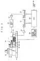
- a motor 12 is attached to a base plate 11, and a turntable 13 is fitted onto a shaft of the motor 12.
- An optical disk 14 is mounted on the turn-table 13 and brought into press-contact with a damping member 15.
- a stator 16a of a linear motor 16 is fixed on the base plate 11 and an optical head 17 is attached to an armature 16b of the linear motor 16.
- an optical position detector 18 is further arranged on the base plate 11 for arranged on the base plate 11 for arranged on the base plate 11 arranged on the base plate 11 is an optical position detector 18 for detecting the position of the optical head 17.
- the output terminal of the optical position detector 18 is connected to an A/D converter 21 through an amplifier 20.
- the output terminal of the A/D converter 21 is connected to a CPU 22.
- the output port of the CPU 22 is connected to a D/A converter 23.
- the output terminal of the D/A converter 23 is connected to a motor driving circuit 25 via an amplifier 24.
- a motor moving direction discriminator 26 is connected to the armature 16b of the linear motor 16.
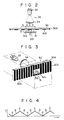
- the optical position detector 18 is attached to the armature 16b of the linear motor 16 and has an optical scale 30 which moves together with the armature 16b, and a photosensor 31 which is fixed on the base plate 11 to face the optical scale 30, as shown in Figs. 2 and 3.
- a light source 32 is arranged opposite to the photosensor 31 with the optical scale 38 interposed between them.
- the light source 32 comprises a light emitter (light- emitting diode) 33 and a collimator lens 34.
- the optical scale 30 includes an optical transparent plate 30a on which grid segments each of width D (e.g.
- the photosensor 31 includes a photoelectric element 31b, masked by a mask 31a, which has an opening whose width is equal to said width D. Namely, the light receiving surface of the photosensor 31 has a width equal to said width D of the optical scale.
- the CPU 22 converts the track number to a desired address.
- the desired address is compared with a position address, which represents the present position of the optical head.
- a start signal is supplied to the D/A converter 23 and converted to an analog signal.
- the analog signal is supplied to the motor drive circuit 25, via the amplifier 24, the motor drive circuit 25 drives the linear motor 16.
- the optical scale 30 moves together with the optical head 17, thus causing the photosensor 31 of the optical position detector 18 to apply a position detecting signal to the A/D converter 21 via the amplifier 20.
- a position detecting signal is applied from the photosensor 31 in this case.
- level signal components, a, b, c and d which are obtained by dividing one scale wave to four equal parts, are digitalized and converted to digital signals of 00, 08,16 and 08; said one scale wave corresponding to one pitch of the scale.
- the digital signal is applied to the CUP 22, it is converted to a position address.
- the CPU performs addition or subtraction between the position address and the desired address, according to the forward or backward moving information applied from the motor moving direction discriminator 26. More specifically, when the digital signals 00, 08, 16 and 08 are applied to the CPU 22 and the motor moving direction discriminator 26 discriminates that the motor is moving in a direction A, the contents of internal register, which correspond to the present position address, are added. When the discriminator 26 discriminates that the motor is moving in a direction B, the contents of the internal register are subtracted.
- the motor-moving direction discriminator 26 may use the back electromotive force of the motor 16 to discriminate whether the motor 16 is moving backward or forward.
- the CPU 22 supplies a motor stop signal to the motor drive circuit 25 through the D/A converter 23 and the amplifier 24.
- the motor drive circuit 25 stops the linear motor responsive to the motor stop signal.
- position detection can be achieved in a more finely divided scale without making the signal process circuit complicated when the output signal of the photosensor, which corresponds to one pitch of the optical scale, is divided to plural equal parts and these signal components are digitized.
- optical position detector employed in the above-described embodiment, has been of the light penetration type, it may be of light reflection type.
Landscapes
- Physics & Mathematics (AREA)
- General Physics & Mathematics (AREA)
- Optical Transform (AREA)
- Length Measuring Devices By Optical Means (AREA)
- Moving Of Head For Track Selection And Changing (AREA)
- Moving Of The Head For Recording And Reproducing By Optical Means (AREA)
Claims (5)
dadurch gekennzeichnet, daß
Applications Claiming Priority (2)
| Application Number | Priority Date | Filing Date | Title |
|---|---|---|---|
| JP1983022148U JPS59128519U (ja) | 1983-02-17 | 1983-02-17 | 位置検出装置 |
| JP22148/83U | 1983-02-17 |
Publications (2)
| Publication Number | Publication Date |
|---|---|
| EP0119488A1 EP0119488A1 (de) | 1984-09-26 |
| EP0119488B1 true EP0119488B1 (de) | 1987-07-15 |
Family
ID=12074773
Family Applications (1)
| Application Number | Title | Priority Date | Filing Date |
|---|---|---|---|
| EP84101679A Expired EP0119488B1 (de) | 1983-02-17 | 1984-02-17 | Lageermittlungsgerät |
Country Status (4)
| Country | Link |
|---|---|
| US (1) | US4607956A (de) |
| EP (1) | EP0119488B1 (de) |
| JP (1) | JPS59128519U (de) |
| DE (1) | DE3464803D1 (de) |
Families Citing this family (15)
| Publication number | Priority date | Publication date | Assignee | Title |
|---|---|---|---|---|
| JPH0677349B2 (ja) * | 1985-03-20 | 1994-09-28 | 株式会社日立製作所 | 光磁気デイスクフアイル装置 |
| DE8621056U1 (de) * | 1986-08-06 | 1986-10-16 | Dr. Johannes Heidenhain Gmbh, 8225 Traunreut | Gekapselte Positionsmeßeinrichtung |
| JP2535873B2 (ja) * | 1987-02-19 | 1996-09-18 | ティアツク株式会社 | デイスク装置 |
| US5059774A (en) * | 1987-10-15 | 1991-10-22 | Ricoh Company, Ltd. | Seek and track control for a rectangular optical card handling apparatus |
| JPH0279223A (ja) * | 1988-09-16 | 1990-03-19 | Hitachi Ltd | 光学式記録再生装置 |
| US5021649A (en) * | 1989-03-28 | 1991-06-04 | Canon Kabushiki Kaisha | Relief diffraction grating encoder |
| US5053685A (en) * | 1990-01-31 | 1991-10-01 | Kensington Laboratories, Inc. | High precision linear actuator |
| US5590102A (en) * | 1995-01-12 | 1996-12-31 | Discovision Associates | Recording informatioin on an optical disc without using pre-manufactured tracks |
| US5978329A (en) * | 1995-06-07 | 1999-11-02 | Discovision Associates | Technique for closed loop servo operation in optical disc tracking control |
| DE19537405A1 (de) * | 1995-10-09 | 1997-04-10 | Leybold Ag | Vorrichtung zum Laserstrahlbelichten eines kreisscheibenförmigen Substrates |
| CN1077715C (zh) * | 1995-12-06 | 2002-01-09 | 迪维安公司 | 聚焦控制的装置和方法 |
| US5689485A (en) * | 1996-04-01 | 1997-11-18 | Discovision Associates | Tracking control apparatus and method |
| US6396052B1 (en) | 2000-04-07 | 2002-05-28 | Lexmark International, Inc. | High precision analog encoder system |
| DE10329374A1 (de) * | 2003-06-30 | 2005-01-20 | Dr. Johannes Heidenhain Gmbh | Abtastbaueinheit einer Positionsmesseinrichtung |
| JP2007076027A (ja) * | 2005-09-12 | 2007-03-29 | Seiko Epson Corp | 位置検出装置およびこの位置検出装置を備える液体吐出装置 |
Citations (1)
| Publication number | Priority date | Publication date | Assignee | Title |
|---|---|---|---|---|
| US4481613A (en) * | 1981-05-01 | 1984-11-06 | Tokyo Shibaura Denki Kabushiki Kaisha | Optical disk apparatus |
Family Cites Families (4)
| Publication number | Priority date | Publication date | Assignee | Title |
|---|---|---|---|---|
| JPS52119904A (en) * | 1976-04-01 | 1977-10-07 | Nippon Gakki Seizo Kk | Arm control device |
| JPS57104815A (en) * | 1980-12-20 | 1982-06-30 | Asahi Optical Co Ltd | Angle measuring apparatus employing line sensor |
| JPS57181434A (en) * | 1981-05-01 | 1982-11-08 | Toshiba Corp | Position detector for head in disc storage device |
| US4409479A (en) * | 1981-12-03 | 1983-10-11 | Xerox Corporation | Optical cursor control device |
-
1983
- 1983-02-17 JP JP1983022148U patent/JPS59128519U/ja active Pending
-
1984
- 1984-02-15 US US06/580,184 patent/US4607956A/en not_active Expired - Fee Related
- 1984-02-17 EP EP84101679A patent/EP0119488B1/de not_active Expired
- 1984-02-17 DE DE8484101679T patent/DE3464803D1/de not_active Expired
Patent Citations (1)
| Publication number | Priority date | Publication date | Assignee | Title |
|---|---|---|---|---|
| US4481613A (en) * | 1981-05-01 | 1984-11-06 | Tokyo Shibaura Denki Kabushiki Kaisha | Optical disk apparatus |
Also Published As
| Publication number | Publication date |
|---|---|
| US4607956A (en) | 1986-08-26 |
| EP0119488A1 (de) | 1984-09-26 |
| JPS59128519U (ja) | 1984-08-29 |
| DE3464803D1 (en) | 1987-08-20 |
Similar Documents
| Publication | Publication Date | Title |
|---|---|---|
| EP0119488B1 (de) | Lageermittlungsgerät | |
| JPH0658779A (ja) | 測定装置 | |
| US4642899A (en) | Measuring attachment | |
| US4775788A (en) | Apparatus for detecting position of a rotating element using a two-grating moire pattern | |
| JPS5828615A (ja) | 移動量測定装置 | |
| ATE67302T1 (de) | Abgeschirmte winkelmesseinrichtung in direktem anbau an einer antriebseinheit. | |
| US6122132A (en) | Disk drive head position encoder | |
| JPS60100015A (ja) | ロ−タリ−エンコ−ダ | |
| US7247839B2 (en) | Encoder for detecting position or displacement of moving body | |
| JPS63167226A (ja) | 分光光度計 | |
| SU1223260A1 (ru) | Устройство дл считывани информации с ленточного носител | |
| JPH0427611B2 (de) | ||
| AU2003290413B2 (en) | An opto-electronic device for angle generation of ultrasonic probe | |
| US5051692A (en) | Processing apparatus for measuring the speed of a rotating body | |
| JPH05164572A (ja) | エンコーダ | |
| JPS55124002A (en) | Optical position detector | |
| JPH0560575A (ja) | 位置検出装置 | |
| JPH0452830Y2 (de) | ||
| EP1014349B1 (de) | Gerät zum Lesen von und/oder Schreiben auf optischen Aufzeichnungsmedien | |
| JP3273201B2 (ja) | 光学式インクリメンタルエンコーダ装置 | |
| JPH0244173Y2 (de) | ||
| SU1149409A1 (ru) | Преобразователь перемещени в код | |
| SU739384A1 (ru) | Устройство дл измерени атмосферной рефракции | |
| JPS6232404B2 (de) | ||
| JPS5965716A (ja) | 変位変換器 |
Legal Events
| Date | Code | Title | Description |
|---|---|---|---|
| PUAI | Public reference made under article 153(3) epc to a published international application that has entered the european phase |
Free format text: ORIGINAL CODE: 0009012 |
|
| 17P | Request for examination filed |
Effective date: 19840314 |
|
| AK | Designated contracting states |
Designated state(s): DE FR NL |
|
| GRAA | (expected) grant |
Free format text: ORIGINAL CODE: 0009210 |
|
| AK | Designated contracting states |
Kind code of ref document: B1 Designated state(s): DE FR NL |
|
| ET | Fr: translation filed | ||
| REF | Corresponds to: |
Ref document number: 3464803 Country of ref document: DE Date of ref document: 19870820 |
|
| PLBE | No opposition filed within time limit |
Free format text: ORIGINAL CODE: 0009261 |
|
| STAA | Information on the status of an ep patent application or granted ep patent |
Free format text: STATUS: NO OPPOSITION FILED WITHIN TIME LIMIT |
|
| 26N | No opposition filed | ||
| PGFP | Annual fee paid to national office [announced via postgrant information from national office to epo] |
Ref country code: DE Payment date: 19940209 Year of fee payment: 11 |
|
| PGFP | Annual fee paid to national office [announced via postgrant information from national office to epo] |
Ref country code: FR Payment date: 19940210 Year of fee payment: 11 |
|
| PGFP | Annual fee paid to national office [announced via postgrant information from national office to epo] |
Ref country code: NL Payment date: 19940228 Year of fee payment: 11 |
|
| PG25 | Lapsed in a contracting state [announced via postgrant information from national office to epo] |
Ref country code: NL Effective date: 19950901 |
|
| PG25 | Lapsed in a contracting state [announced via postgrant information from national office to epo] |
Ref country code: FR Effective date: 19951031 |
|
| NLV4 | Nl: lapsed or anulled due to non-payment of the annual fee |
Effective date: 19950901 |
|
| PG25 | Lapsed in a contracting state [announced via postgrant information from national office to epo] |
Ref country code: DE Effective date: 19951101 |
|
| REG | Reference to a national code |
Ref country code: FR Ref legal event code: ST |