EP0119379A2 - Scaffolding - Google Patents
Scaffolding Download PDFInfo
- Publication number
- EP0119379A2 EP0119379A2 EP84100070A EP84100070A EP0119379A2 EP 0119379 A2 EP0119379 A2 EP 0119379A2 EP 84100070 A EP84100070 A EP 84100070A EP 84100070 A EP84100070 A EP 84100070A EP 0119379 A2 EP0119379 A2 EP 0119379A2
- Authority
- EP
- European Patent Office
- Prior art keywords
- coupling
- wall
- working platform
- anchor
- perforations
- Prior art date
- Legal status (The legal status is an assumption and is not a legal conclusion. Google has not performed a legal analysis and makes no representation as to the accuracy of the status listed.)
- Granted
Links
Images
Classifications
-
- E—FIXED CONSTRUCTIONS
- E04—BUILDING
- E04G—SCAFFOLDING; FORMS; SHUTTERING; BUILDING IMPLEMENTS OR AIDS, OR THEIR USE; HANDLING BUILDING MATERIALS ON THE SITE; REPAIRING, BREAKING-UP OR OTHER WORK ON EXISTING BUILDINGS
- E04G5/00—Component parts or accessories for scaffolds
- E04G5/06—Consoles; Brackets
-
- E—FIXED CONSTRUCTIONS
- E04—BUILDING
- E04G—SCAFFOLDING; FORMS; SHUTTERING; BUILDING IMPLEMENTS OR AIDS, OR THEIR USE; HANDLING BUILDING MATERIALS ON THE SITE; REPAIRING, BREAKING-UP OR OTHER WORK ON EXISTING BUILDINGS
- E04G5/00—Component parts or accessories for scaffolds
- E04G5/04—Means for fastening, supporting, or bracing scaffolds on or against building constructions
- E04G5/046—Means for fastening, supporting, or bracing scaffolds on or against building constructions for fastening scaffoldings on walls
-
- E—FIXED CONSTRUCTIONS
- E04—BUILDING
- E04G—SCAFFOLDING; FORMS; SHUTTERING; BUILDING IMPLEMENTS OR AIDS, OR THEIR USE; HANDLING BUILDING MATERIALS ON THE SITE; REPAIRING, BREAKING-UP OR OTHER WORK ON EXISTING BUILDINGS
- E04G5/00—Component parts or accessories for scaffolds
- E04G5/06—Consoles; Brackets
- E04G5/062—Consoles; Brackets specially adapted for attachment to building walls
Definitions
- the invention relates to a working platform which can be attached to an anchor, in particular to a formwork tie rod, in the upper region of a preferably concrete wall and is arranged with its accessible surface approximately at the height of the upper edge of the wall.
- Such work platforms are known and are used to enable a bricklayer to wall up a further wall piece, to hold and carry formwork for a next higher wall or to provide appropriate safety at the bottom edge of the sloping roof during roofing work.
- Such work platforms can be particularly well attached to a concrete wall, wherein the formwork tie rod originally belonging to the formwork or an opening left by it can be used to form or take up the anchor for holding the work platform.
- the Schalungszug - anchors withdraw from the wall depending on the formwork at different heights.
- a coupling for connecting the working platform to the formwork tie rod or a holding anchor inserted in its opening can be adjusted in height and fixed on the working platform.
- the coupling can thus engage the formwork tie rod or its position, but the work platform can be oriented towards the upper edge of the wall.
- the work platform is releasably attached to the coupling and has several fastening points arranged at different heights for this coupling. This results in a particularly simple construction.
- the coupling has at least two perforations
- the working platform on a preferably vertical support each has pairs of perforations which are offset in height from one another and whose distance corresponds to the spacing of the perforations on the coupling, so that the connection can be established with at least two bolts is.
- a work platform designated as a whole has a walk-on running surface 2 and a railing 3 remote from the wall.
- a horizontal support 4 and a vertical support 5 and a climbing strut 6 connecting them are arranged below the running surface.
- the entire working platform 1 can be attached according to FIG. 2 to an anchor 7, preferably to a formwork tie anchor remaining in it from the previous manufacture of the wall 8, the walkable running surface 2 according to FIG. 1 being approximately at the height of the upper edge 9 on the wall 8 should come to rest.
- a coupling 10, shown in more detail in FIG. 2, for connecting the work platform 1 to the anchor 7 on the work platform 1 is adjustable in height and definable.
- the tread 2 can be adjusted to the height of the upper edge 9 of the wall 8 largely independently of the position of the armature 7.
- the work platform 1 is detachably attached to the coupling 10 and has a plurality of fastening points 11 arranged at different heights for this coupling 10.
- Fig. 2 it can be seen that the coupling 10 has two superposed perforations, while the work platform 1 on the vertical support 5 each has mutually offset perforation pairs, in which the perforations are each half the distance according to the distance of the perforations on the coupling Have 10. This enables a connection between the coupling 10 and the vertical support 5 and thus the working platform 1 with the aid of the screw bolts 12 visible in FIG. 2.
- the coupling 10 is arranged in the upper region of the vertical support 5 and the support 5 has at its opposite lower end a transverse support 13 for contacting the wall 8. This results in a stable mounting in which the forces coming from the cantilevered running surface 2 are good the anchor 7 and the wall 8 can be introduced.
- the coupling 10 has at least one angled, possibly also a U-shaped cross-sectional profile, and the leg 14, which runs parallel to the wall 8 in the position of use, now has the perforations for the releasable connecting bolts 12.
- the coupling 10 has at least one transverse bolt 15 which is arranged at a distance from the support 5 closer to the wall 8 and which can be suspended in an anchor shoe 16 or the like.
Abstract
Description
Die Erfindung betrifft eine Arbeitsbühne, die im oberen Bereich einer vorzugsweise betonierten Wand an einem Anker, insbesondere an einem Schalungszuganker anhängbar ist und mit ihrer begehbaren Fläche etwa auf der Höhe des oberen Randes der Wand angeordnet ist.The invention relates to a working platform which can be attached to an anchor, in particular to a formwork tie rod, in the upper region of a preferably concrete wall and is arranged with its accessible surface approximately at the height of the upper edge of the wall.
Derartige Arbeitsbühnen sind bekannt und dienen dazu, einem Maurer das Höhermauern eines weiteren Wandstückes zu ermöglichen, eine Schalung für eine nächst höhere Wandund aufzunehmen und zu tragen oder, um bei Dachdeckerarbeiten entsprechende Sicherheit am unteren Rand der Dachschräge zu bieten. Dabei lassen sich solche Arbeitsbühnen besonders gut an eine betonierte Wand anhängen, wobei der ursprünglich zu den Schalungen gehörende Schalungszuganker oder eine von diesem hinterlassene öffnung verwendet werden kann, um den Anker zum Halten der Arbeitsbühne zu bilden oder aufzunehmen. Dabei besteht jedoch das Problem, daß die Schalungszug- anker je nach verwendeter Schalung in unterschiedlichen Höhen aus der Wand austreten.Such work platforms are known and are used to enable a bricklayer to wall up a further wall piece, to hold and carry formwork for a next higher wall or to provide appropriate safety at the bottom edge of the sloping roof during roofing work. Such work platforms can be particularly well attached to a concrete wall, wherein the formwork tie rod originally belonging to the formwork or an opening left by it can be used to form or take up the anchor for holding the work platform. However, there is the problem that the Schalungszug - anchors withdraw from the wall depending on the formwork at different heights.
Es besteht deshalb die Aufgabe, eine Arbeitsbühne der eingangs erwähnten Art zu schaffen, die trotz beliebiger Höhe eines zuvor beim Betonieren der Wand verwendeten Schalungszugankers etwa auf der Höhe des oberen Randes der Wand angeordnet werden kann.It is therefore the task of creating a working platform of the type mentioned at the outset which, despite any height of a formwork tie rod previously used when concreting the wall, can be arranged approximately at the height of the upper edge of the wall.
Die Lösung dieser Aufgabe besteht darin, daß eine Kupplung zum Verbinden der Arbeitsbühne mit dem Schalungszuganker oder einem in dessen Öffnung eingesetzten Halteankter an der Arbeitsbühne höhenverstellbar und festlegbar ist. In überraschend einfacher Weise kann so die Kupplung jeweils an dem Schalungszuganker bzw. dessen Position angreifen, die Arbeitsbühne aber auf den oberen Rand der Wand hin ausgerichtet werden. Dabei ist es zweckmäßig, daß die Arbeitsbühne lösbar an der Kupplung befestigt ist und mehrere in unterschiedlichen Höhen angeordnete Befestigungsstellen für diese Kupplung aufweist. Dies ergibt eine besonders einfache Konstruktion.The solution to this problem is that a coupling for connecting the working platform to the formwork tie rod or a holding anchor inserted in its opening can be adjusted in height and fixed on the working platform. In a surprisingly simple manner, the coupling can thus engage the formwork tie rod or its position, but the work platform can be oriented towards the upper edge of the wall. It is expedient that the work platform is releasably attached to the coupling and has several fastening points arranged at different heights for this coupling. This results in a particularly simple construction.
Besonders zweckmäßig ist es, wenn die Kupplung wenigstens zwei Lochungen aufweist, und die Arbeitsbühne an einem vorzugsweise vertikalen Träger jeweils in der Höhe gegeneinander versetzte Lochungspaare hat, deren Abstand dem Abstand der Lochungen an der Kupplung entspricht, so daß die Verbindung mit wenigstens zwei Bolzen herstellbar ist.It is particularly expedient if the coupling has at least two perforations, and the working platform on a preferably vertical support each has pairs of perforations which are offset in height from one another and whose distance corresponds to the spacing of the perforations on the coupling, so that the connection can be established with at least two bolts is.
Weitere Ausgestaltungen der Erfindung sind Gegenstand weiterer Ansprüche.Further embodiments of the invention are the subject of further claims.
Nachstehend ist die Erfindung mit ihren ihr als wesentlich zugehörenden Einzelheiten anhand der Zeichnung noch näher beschrieben. Es zeigt in zum Teil schematisierter Darstellung:
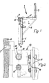
- Fig. 1 eine Seitenansicht einer erfindungsgemäßen Arbeitsbühne und
- Fig. 2 in vergrößertem Maßstab eine teilweise im Schnitt gehaltene Seitenansicht der Kupplung zum Verbinden der Arbeitsbühne mit einer Wand.
- Fig. 1 is a side view of a work platform according to the invention and
- Fig. 2 on an enlarged scale, a partially sectioned side view of the coupling for connecting the work platform to a wall.
Eine im ganzen mit 1 bezeichnete Arbeitsbühne hat eine begehbare Lauffläche 2 sowie ein wandfernes Geländer 3. Unterhalb der Lauffläche sind ein horizontaler Träger 4 sowie ein vertikaler Träger 5 und eine diese verbindende Aussteigungsstrebe 6 angeordnet.A work platform designated as a whole has a walk-on running
Die gesamte Arbeitsbühne 1 ist gemäß Fig. 2 an einem Anker 7, bevorzugt an einem von der vorangegangenen Herstellung der Wand 8 in dieser verbliebenen Schalungszuganker anhängbar, wobei die begehbare Lauffläche 2 gemäß Fig. 1 etwa auf der Höhe des oberen Randes 9 an der Wand 8 zu liegen kommen soll.The entire working platform 1 can be attached according to FIG. 2 to an
Da die Anordnung des Ankers 7 davon abhängt, wo bei der vorher verwendeten Schalung zur Herstellung der Wand 8 ein oberer Schalungszuganker vorgesehen war, ist eine in Fig. 2 näher dargestellte Kupplung 10 zum Verbinden der Arbeitsbühne 1 mit dem Anker 7 an der Arbeitsbühne 1 höhenverstellbar und festlegbar. Somit kann die Lauffläche 2 weitgehend unabhängig von der Lage des Ankers 7 auf die Höhe des oberen Randes 9 der Wand 8 eingestellt werden.Since the arrangement of the
Dabei ist die Arbeitsbühne 1 lösbar an der Kupplung 10 befestigt und weist mehrere in unterschiedlichen Höhen angeordnete Befestigungsstellen 11 für diese Kupplung 10 auf.The work platform 1 is detachably attached to the
In Fig. 2 erkennt man, daß die Kupplung 10 zwei übereinanderliegende Lochungen aufweist, während die Arbeitsbühne 1 an dem vertikalen Träger 5 jeweils in der Höhe gegeneinander versetzte Lochungspaare hat, bei denen die Lochungen jeweils den halben Abstand gemäß dem Abstand der Lochungen an der Kupplung 10 haben. Dadurch ist eine Verbindung zwischen der Kupplung 10 und dem vertikalen Träger 5 und somit der Arbeitsbühne 1 mit Hilfe der in Fig. 2 sichtbaren Schraubenbolzen 12 möglich.In Fig. 2 it can be seen that the
Die Kupplung 10 ist im oberen Bereich des vertikalen Trägers 5 angeordnet und der Träger 5 hat an seinem entgegengesetzten unteren Ende eine Querabstützung 13 zum Anlegen an die Wand 8. Dies ergibt eine stabile Halterung, bei der die von der auskragenden Lauffläche 2 kommenden Kräfte gut in den Anker 7 und die Wand 8 eingeleitet werden können. Die Kupplung 10 hat dabei zumindest ein winkliges, gegebenenfalls auch ein U-förmiges Querschnittsprofil und der in Gebrauchsstellung parallel zur Wand 8 verlaufende Schenkel 14 hat nun die Lochungen für die lösbaren Verbindungsbolzen 12.The
Man erkennt in der Zeichnung ferner, daß die Kupplung 10 wenigstens einen mit Abstand zu dem Träger 5 näher zur Wand 8 angeordneten Querbolzen 15 aufweist, der in einem Ankerschuh 16 od. dgl. mit dem Wandanker 7 verbundenen oder verbindbaren Teil einhängbar ist. Darunter befindet sich ein weiterer Bolzen 17 als Aushebesicherung. Dieser wird nach dem Einhängen des Querbolzens 15 in die nach oben offene Öffnung 18 des Ankerschuhs 16 unterhalg dieses Schuhs durch die Kupplung 10 gesteckt. Dann können auch Erschütterungen an der Arbeitsbühne 1 nicht mehr zu einem ungewollten Ausheben führen.It can also be seen in the drawing that the
Alle in der vorstehenden Beschreibung, den Ansprüchen und der Zeichnung dargestellten Merkmale und Konstruktionsdetails können sowohl einzeln als auch in beliebiger Kombination miteinander wesentliche Bedeutung haben.All in the above description, the claims Features and construction details shown in the drawing can have significant meaning both individually and in any combination with one another.
Claims (7)
Priority Applications (1)
| Application Number | Priority Date | Filing Date | Title |
|---|---|---|---|
| AT84100070T ATE22953T1 (en) | 1983-03-22 | 1984-01-05 | WORK PLATFORM. |
Applications Claiming Priority (2)
| Application Number | Priority Date | Filing Date | Title |
|---|---|---|---|
| DE8308465U | 1983-03-22 | ||
| DE19838308465U DE8308465U1 (en) | 1983-03-22 | 1983-03-22 | WORKING STAGE |
Publications (3)
| Publication Number | Publication Date |
|---|---|
| EP0119379A2 true EP0119379A2 (en) | 1984-09-26 |
| EP0119379A3 EP0119379A3 (en) | 1984-12-19 |
| EP0119379B1 EP0119379B1 (en) | 1986-10-15 |
Family
ID=6751460
Family Applications (1)
| Application Number | Title | Priority Date | Filing Date |
|---|---|---|---|
| EP84100070A Expired EP0119379B1 (en) | 1983-03-22 | 1984-01-05 | Scaffolding |
Country Status (5)
| Country | Link |
|---|---|
| EP (1) | EP0119379B1 (en) |
| AT (1) | ATE22953T1 (en) |
| DE (2) | DE8308465U1 (en) |
| DK (1) | DK155680C (en) |
| NO (1) | NO841104L (en) |
Cited By (4)
| Publication number | Priority date | Publication date | Assignee | Title |
|---|---|---|---|---|
| GB2299126A (en) * | 1995-03-24 | 1996-09-25 | King M J Eng Co | Walkway system |
| CN110700560A (en) * | 2019-11-11 | 2020-01-17 | 浙江宇之航科技工程有限公司 | Wall-attached hanging piece applied to attached lifting scaffold |
| CN111608385A (en) * | 2020-05-23 | 2020-09-01 | 成都市天柱建筑工程有限公司 | Wall connecting device for industrial factory building outer wall scaffold and use method thereof |
| CN111705668A (en) * | 2020-06-19 | 2020-09-25 | 山西省交通规划勘察设计院有限公司 | Method for fixedly connecting highway bridge pier support overhauling fence and bridge pier |
Families Citing this family (1)
| Publication number | Priority date | Publication date | Assignee | Title |
|---|---|---|---|---|
| DE3639129A1 (en) * | 1986-11-15 | 1988-05-26 | Noe Schaltechnik Kg | Climbing bracket |
Citations (4)
| Publication number | Priority date | Publication date | Assignee | Title |
|---|---|---|---|---|
| FR2136395A5 (en) * | 1972-04-10 | 1972-12-22 | Outinord Sa Ets | |
| FR2350112A2 (en) * | 1976-05-07 | 1977-12-02 | Seine & Lys | Fall break for building workers - has bracket arches of flexible material supporting net apron and holding it taut |
| FR2370150A1 (en) * | 1976-11-03 | 1978-06-02 | Desbarats Jean | Climbing working platform for building construction - has wall bracket support transferred as new floor is added and platform lifted |
| WO1982001026A1 (en) * | 1980-09-11 | 1982-04-01 | Wallther H | Device for detachably supporting a work stand on a wall surface or the like |
-
1983
- 1983-03-22 DE DE19838308465U patent/DE8308465U1/en not_active Expired
-
1984
- 1984-01-05 EP EP84100070A patent/EP0119379B1/en not_active Expired
- 1984-01-05 DE DE8484100070T patent/DE3460995D1/en not_active Expired
- 1984-01-05 AT AT84100070T patent/ATE22953T1/en not_active IP Right Cessation
- 1984-02-28 DK DK116084A patent/DK155680C/en active
- 1984-03-21 NO NO841104A patent/NO841104L/en unknown
Patent Citations (4)
| Publication number | Priority date | Publication date | Assignee | Title |
|---|---|---|---|---|
| FR2136395A5 (en) * | 1972-04-10 | 1972-12-22 | Outinord Sa Ets | |
| FR2350112A2 (en) * | 1976-05-07 | 1977-12-02 | Seine & Lys | Fall break for building workers - has bracket arches of flexible material supporting net apron and holding it taut |
| FR2370150A1 (en) * | 1976-11-03 | 1978-06-02 | Desbarats Jean | Climbing working platform for building construction - has wall bracket support transferred as new floor is added and platform lifted |
| WO1982001026A1 (en) * | 1980-09-11 | 1982-04-01 | Wallther H | Device for detachably supporting a work stand on a wall surface or the like |
Cited By (5)
| Publication number | Priority date | Publication date | Assignee | Title |
|---|---|---|---|---|
| GB2299126A (en) * | 1995-03-24 | 1996-09-25 | King M J Eng Co | Walkway system |
| GB2299126B (en) * | 1995-03-24 | 1998-10-21 | King M J Eng Co | Walkway system |
| CN110700560A (en) * | 2019-11-11 | 2020-01-17 | 浙江宇之航科技工程有限公司 | Wall-attached hanging piece applied to attached lifting scaffold |
| CN111608385A (en) * | 2020-05-23 | 2020-09-01 | 成都市天柱建筑工程有限公司 | Wall connecting device for industrial factory building outer wall scaffold and use method thereof |
| CN111705668A (en) * | 2020-06-19 | 2020-09-25 | 山西省交通规划勘察设计院有限公司 | Method for fixedly connecting highway bridge pier support overhauling fence and bridge pier |
Also Published As
| Publication number | Publication date |
|---|---|
| DK155680C (en) | 1989-09-25 |
| DK116084A (en) | 1984-09-23 |
| DK155680B (en) | 1989-05-01 |
| DK116084D0 (en) | 1984-02-28 |
| ATE22953T1 (en) | 1986-11-15 |
| DE8308465U1 (en) | 1983-09-08 |
| EP0119379B1 (en) | 1986-10-15 |
| DE3460995D1 (en) | 1986-11-20 |
| NO841104L (en) | 1984-09-24 |
| EP0119379A3 (en) | 1984-12-19 |
Similar Documents
| Publication | Publication Date | Title |
|---|---|---|
| DE2814930A1 (en) | CLIMBING FRAME | |
| EP0064183B1 (en) | Climbing form | |
| WO2002103136A2 (en) | Dismountable scaffolding | |
| DE2217584C3 (en) | Climbing formwork for a concrete wall formwork | |
| EP0119379B1 (en) | Scaffolding | |
| DE3108020A1 (en) | "PROTECTIVE DEVICE FOR METAL FRAME" | |
| CH656171A5 (en) | METHOD FOR ASSEMBLING AND STRETCHING A CEILING FOR CABLING WORK AND EQUIPMENT FOR CARRYING OUT THE METHOD. | |
| DE820963C (en) | Scaffolding with stands made of tubes | |
| DE202022105308U1 (en) | Device for preventing people from falling | |
| DE2057263C3 (en) | Device for supporting trench walls | |
| DE2407103A1 (en) | Ladder scaffolding supporting working-platform - with triangle-grouped cantilevered supports with hooked traverses on base bar | |
| DE4114328C2 (en) | Device for hanging a bracket frame element | |
| EP1134331A2 (en) | Set of elements for a scaffold | |
| DE2530639A1 (en) | FORMWORK SCAFFOLDING FOR CEILINGS | |
| DE3303070A1 (en) | Boundary like a railing or a fence | |
| DE4318012C2 (en) | Device for erecting building walls | |
| DE811292C (en) | Formwork scaffolding for beamless ceilings | |
| DE3522632C1 (en) | Roof scaffolding | |
| DE19525183A1 (en) | Support structure for maintaining frame at given height in construction of wall - has horizontal rod with shaped hole to receive telescopically adjustable bar | |
| DE872112C (en) | Formwork for building walls in loose or cast concrete | |
| DE548162C (en) | Timber frame construction | |
| EP1452668A2 (en) | Shuttering | |
| AT248669B (en) | Formwork for concrete walls | |
| DE815097C (en) | Formwork scaffolding for concrete walls | |
| DE3428095A1 (en) | Holding apparatus serving for increasing the stability of a floor shuttering support in construction |
Legal Events
| Date | Code | Title | Description |
|---|---|---|---|
| PUAI | Public reference made under article 153(3) epc to a published international application that has entered the european phase |
Free format text: ORIGINAL CODE: 0009012 |
|
| AK | Designated contracting states |
Designated state(s): AT BE CH DE FR GB IT LI LU NL SE |
|
| PUAL | Search report despatched |
Free format text: ORIGINAL CODE: 0009013 |
|
| AK | Designated contracting states |
Designated state(s): AT BE CH DE FR GB IT LI LU NL SE |
|
| 17P | Request for examination filed |
Effective date: 19841116 |
|
| ITF | It: translation for a ep patent filed |
Owner name: ING. ZINI MARANESI & C. S.R.L. |
|
| GRAA | (expected) grant |
Free format text: ORIGINAL CODE: 0009210 |
|
| AK | Designated contracting states |
Kind code of ref document: B1 Designated state(s): AT BE CH DE FR GB IT LI LU NL SE |
|
| REF | Corresponds to: |
Ref document number: 22953 Country of ref document: AT Date of ref document: 19861115 Kind code of ref document: T |
|
| REF | Corresponds to: |
Ref document number: 3460995 Country of ref document: DE Date of ref document: 19861120 |
|
| ET | Fr: translation filed | ||
| PLBE | No opposition filed within time limit |
Free format text: ORIGINAL CODE: 0009261 |
|
| STAA | Information on the status of an ep patent application or granted ep patent |
Free format text: STATUS: NO OPPOSITION FILED WITHIN TIME LIMIT |
|
| 26N | No opposition filed | ||
| ITTA | It: last paid annual fee | ||
| PGFP | Annual fee paid to national office [announced via postgrant information from national office to epo] |
Ref country code: DE Payment date: 19931230 Year of fee payment: 11 |
|
| EPTA | Lu: last paid annual fee | ||
| PGFP | Annual fee paid to national office [announced via postgrant information from national office to epo] |
Ref country code: LU Payment date: 19950101 Year of fee payment: 12 |
|
| PGFP | Annual fee paid to national office [announced via postgrant information from national office to epo] |
Ref country code: SE Payment date: 19950123 Year of fee payment: 12 |
|
| PGFP | Annual fee paid to national office [announced via postgrant information from national office to epo] |
Ref country code: GB Payment date: 19950127 Year of fee payment: 12 Ref country code: FR Payment date: 19950127 Year of fee payment: 12 |
|
| EAL | Se: european patent in force in sweden |
Ref document number: 84100070.6 |
|
| PGFP | Annual fee paid to national office [announced via postgrant information from national office to epo] |
Ref country code: AT Payment date: 19950131 Year of fee payment: 12 Ref country code: NL Payment date: 19950131 Year of fee payment: 12 |
|
| PGFP | Annual fee paid to national office [announced via postgrant information from national office to epo] |
Ref country code: CH Payment date: 19950213 Year of fee payment: 12 |
|
| PGFP | Annual fee paid to national office [announced via postgrant information from national office to epo] |
Ref country code: BE Payment date: 19950307 Year of fee payment: 12 |
|
| PG25 | Lapsed in a contracting state [announced via postgrant information from national office to epo] |
Ref country code: DE Effective date: 19951003 |
|
| PG25 | Lapsed in a contracting state [announced via postgrant information from national office to epo] |
Ref country code: LU Free format text: LAPSE BECAUSE OF NON-PAYMENT OF DUE FEES Effective date: 19960105 Ref country code: AT Effective date: 19960105 Ref country code: GB Effective date: 19960105 |
|
| PG25 | Lapsed in a contracting state [announced via postgrant information from national office to epo] |
Ref country code: SE Effective date: 19960106 |
|
| PG25 | Lapsed in a contracting state [announced via postgrant information from national office to epo] |
Ref country code: BE Effective date: 19960131 Ref country code: CH Effective date: 19960131 Ref country code: LI Effective date: 19960131 |
|
| BERE | Be: lapsed |
Owner name: MAIER JOSEF Effective date: 19960131 |
|
| PG25 | Lapsed in a contracting state [announced via postgrant information from national office to epo] |
Ref country code: NL Effective date: 19960801 |
|
| GBPC | Gb: european patent ceased through non-payment of renewal fee |
Effective date: 19960105 |
|
| REG | Reference to a national code |
Ref country code: CH Ref legal event code: PL |
|
| PG25 | Lapsed in a contracting state [announced via postgrant information from national office to epo] |
Ref country code: FR Effective date: 19960930 |
|
| NLV4 | Nl: lapsed or anulled due to non-payment of the annual fee |
Effective date: 19960801 |
|
| EUG | Se: european patent has lapsed |
Ref document number: 84100070.6 |
|
| REG | Reference to a national code |
Ref country code: FR Ref legal event code: ST |