EP0119004A2 - Système de communication à boucle - Google Patents
Système de communication à boucle Download PDFInfo
- Publication number
- EP0119004A2 EP0119004A2 EP84300794A EP84300794A EP0119004A2 EP 0119004 A2 EP0119004 A2 EP 0119004A2 EP 84300794 A EP84300794 A EP 84300794A EP 84300794 A EP84300794 A EP 84300794A EP 0119004 A2 EP0119004 A2 EP 0119004A2
- Authority
- EP
- European Patent Office
- Prior art keywords
- transmit
- signal
- clock
- data
- terminal
- Prior art date
- Legal status (The legal status is an assumption and is not a legal conclusion. Google has not performed a legal analysis and makes no representation as to the accuracy of the status listed.)
- Granted
Links
Images
Classifications
-
- H—ELECTRICITY
- H04—ELECTRIC COMMUNICATION TECHNIQUE
- H04L—TRANSMISSION OF DIGITAL INFORMATION, e.g. TELEGRAPHIC COMMUNICATION
- H04L12/00—Data switching networks
- H04L12/28—Data switching networks characterised by path configuration, e.g. LAN [Local Area Networks] or WAN [Wide Area Networks]
- H04L12/42—Loop networks
- H04L12/422—Synchronisation for ring networks
Definitions
- the present invention is in the field of data communications, and more particularly, relates to the synchronization of terminals in ring communications networks.
- Ring communications networks generally include a plurality of terminals coupled in series along a unidirectional signal path.
- any of the terminals coupled to the ring may transmit or receive data on the ring according to a ring protocol.
- it is a relatively simple matter to synchronize all the terminals for example, by providing the clock (or timing) signals for use at the respective terminals from a common oscillator.
- clock (or timing) signals for use at the respective terminals from a common oscillator.
- master oscillator To achieve inter- terminal synchronization in such systems timing information is added to the transmitted data.
- the ring timing information is inserted by a single terminal. All other terminals adapt their transmit rates to the observed incoming data rates. This approach suffers from the disadvantage of having to identify a crucial terminal.
- a distributed averaging of the transmit rate is achieved where each terminal has an invariant local oscillator whose frequency is some multiple of the transmit bit rate.
- a terminal's transmit bit rate is then discretely adjusted in accordance with the observed input data rate. The adjustment occurs in time blocks so that the resultant bit rates through the terminal are varied during those blocks while being substantially fixed at other times.
- data packets at various terminals might have the same fixed number of bits pass through, but the bits would have adjustable lengths; adjusted so that there is a predetermined nominal clock rate around the ring.
- such systems circulate a synchronization word having a fixed number of bits, where the respective bits are discretely variable in length, due to the adjustment. Between synchronization words, the data is clocked at a fixed frequency. While such systems are effective in many applications, there are disadvantages. For example, the sudden introduction of adjustable length bits requires relatively high bandwidth and also prohibits many forms of transceiver design.
- the present invention is directed to a communications network including a plurality of terminals coupled together to provide a unidirectional communications ring.
- Each of the terminals is coupled in series along the ring.
- Each ter- minal is adapted to transmit (at an associated fixed data rate) a digital signal to the next downstream terminal on the ring.
- the data rates for the respective terminals in general must be nominally close, but do not have to be identical.
- the digital signal has the form of a succession of data packets interleaved with a succession of synchronization words, or packets.
- the data packets have a number of ,bits less than or equal to a predetermined limit, and the synchronization packets have a number of bits between predetermined minimum and maximum limits.
- the synchronization packet includes a succession of bits having a run with the same binary value (e.g. all binary 1's or all binary 0's) bounded on each end by the opposite binary value.
- data packets may not include a run having bits of the same binary value as the run in the synchronization packets and having a length equal to or greater than the minimum length synchronization packet.
- Each terminal is adapted to receive a digital signal at the data rate associated with the next upstream terminal.
- each local terminal there is a detector for detecting the received synchronization packets and data packets. From these packets, a succession of synchronization packets and associated data packets are generated for transmission to the next downstream terminal on the ring at a predetermined fixed data rate associated with the local terminal.
- the data of each transmitted data packet matches bit for bit the data of the corresponding received data packet.
- the number of bits in the transmit synchronization packet differs from the number of bits in the associated received synchronization packet in a manner so that the data rate for the composite packet formed by the transmitted data packet and associated synchronization data packet corresponds to the transmit data rate for the terminal. The difference varies between predetermined minimum and maximum limits, and may be zero for two terminals having substantially the same transient bit rate.
- the transmit data rate for any local terminal is related to the transmit data rate of other terminals on the ring. This relationship may be expressed in terms of the length (L) of data packets where L ⁇ W (1- T 2 )/2 T where T is the tolerance of the bit rate associated with the terminal and W is representative of the maximum phase jitter of the signal.
- the detector and transmit generator include a transmit clock generator for generating a transmit clock signal having a repetition rate corresponding to the local terminal transmit data rate.
- An elastic clock generator generates n elastic clock signals, where n is an integer. Each elastic clock signal has a repetition rate corresponding to the transmit data rate for the local terminal, and each is shifted in time with respect to the transmit clock signal by a different multiple of 1/n x the period of the transmit clock signal.
- a digital sample and hold network is adapted to sample and hold the received data signal from the upstream terminal at times determined by an applied one of the elastic clock signals.
- An output shift register clocks the held samples at the transmit clock rate to generate the transmit data packets and the transmit synchronization packets.
- a controller is adapted to detect when the sampled and held values correspond to the synchronization packet, and in response to that detection, select one of the elastic clock signals for application to the sample and hold network. Upon such detection, an elastic clock signal is selected which is shifted in time (by periods substantially equal to one-half the period of the transmit clock signal) from the first -transition which follows the detected synchronization packet.
- each local terminal transmits data to the next downstream terminal referenced to that local terminal's own invariant oscillator.
- the data packets of the received digital signal are interleaved with synchronization packets having elastic length that may be increased or decreased to provide appropriate synchronization around the ring.
- synchronization is achieved by a shallow discretely adjusted delay (first in - first out) buffer and sample point readjustment network.
- the first-in and first-out buffer is read at the fixed transmit data rate, and loaded at that same rate until the period of elasticity is detected. At that point, the sample point is reselected so as to fall substantially in the middle of the transmit bit window effectively changing the first-in first-out buffer depth.
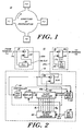
- Fig. 1 shows a communication network 10 in accordance with the present invention.
- the exemplary network 10 includes four terminals Tl, T2, T3, and T4 coupled in series along a unidirectional signal path to form a communications ring.
- Each of the terminals includes an input port and an output port.
- the input port of each terminal is coupled to the output port of the upstream terminal and the output port of each terminal is coupled to the input port of the next downstream terminal.
- the present embodiment is particularly adapted to a system in which the digital signals passed from terminal to terminal on network 10 include a succession of data packets interleaved with an associated succession of synchronization packets.
- L maximum bit length for a data packet
- T the frequency tolerance of the local terminal bit rate ( f max- f nom/ f nom)
- the synchronization packets have a number of bits between predetermined minimum and maximum limits, for example, 6 and 14 in the present embodiment.
- the synchronization packet in effect is a ten-bit word, plus or minus four bits. These limits may differ in other embodiments.
- the lower limit for a given nominal synchronization packet length is dependent on the probabilities in the system that successive terminals would have associated bit rates requiring the shaving off of bits of that packet down to the lower limit.
- the upper limit for a given nominal synchronization packet length is dependent on the system throughput requirements for data in the data packets and physical media considerations.
- 1024 bit data packets are used with synchronization packets nominally having ten bits plus or minus four bits.
- the synchronization packets includes a succession of bits all having the same binary "I". Data packets are restricted to have no run of more than five consecutive 1's.
- the data may be passed from terminal to terminal by a modulated carrier.
- the received signal may be converted to a demodulated NRZI digital signal.
- the NRZI signal may be converted to regenerated NRZ data using a phase locked loop. In that operation, the phase locked loop removes amplitude and phase noise from the recovered data.
- the reconstructed, PLL referenced, NRZ data has a bit rate determined by the upstream terminal's bit rate. Correspondingly, this rate may vary relative to this local terminal bit rate in accordance with the crystal tolerances, e.g. .0005 percent, and aging parameters, e.g..0005 percent per year. This difference necessitates a periodic phase adjustment of the PLL-NRZ data to the local terminal bit rate to prevent the local terminal sampling point from drifting too far from the observed center of the bit window. A 1-2 bit variable delay is provided to permit this. When the limits of the delay element are reached, a bit is selectively dropped or added to the passing data stream. In effect, this modulates the transmission rate of the local terminal.
- the minimum adjustment step is the period of the local bit (HS) sample clock.
- the delay adjustment is done at discrete moments in time.
- the opportunities for the adjustment are provided by the periodic presence of the synchronization in packets which are interleaved with the passing data packet.
- the synchronization packets are identified by a bit pattern whose uniqueness is ensured by the bit stuff protocol.
- an all"1" pattern is bounded by "0-1" and "1-0" transitions.
- the elasticity in the synchronization packet length accommodates the bit insertion or deletion that takes place when the limits of the variable delay element are reached.
- variable delay is discretely adjusted. It varies from 1 to 2 bit times in steps that are equal in length to the period of a relatively fast local oscillator, the bit sample (HS) clock.
- this delay is introduced by the two cascaded flipflops of blocks 34 and 18.
- the second flipflop is loaded from the first at an unvarying rate that is equal to the local terminal bit rate (Tx) clock.
- the first flipflop samples the PLL-NRZ data approximately in the middle of the bit window.
- the length of the delay is one Tx clock period plus the time between the first flipflop's sampling and the second flipflop's sample loading.
- the first flipflop's sample point is reselected whenever a synchronization character passes.
- a synchronization packet is determined to be passing whenever 6 or more 1's are loaded in succession into this first flipflop.
- the first flipflopt's sampling is inhibited until a binary 0 (synchronized to the HS clock signal) is detected in the PLL-NRZ data. The appearance of this zero starts a counter which determines the optimal sample point. The reselection of the sample point effectively changes the observed delay.
- the reselection may alternatively not affect the passing synchronization packet, truncate it by 1 bit, or extend it by 1 bit.
- the synchronization packet size will only be altered when a delay limit is reached. If the delay is currently at maximum and needs to grow, it will drop back to the minimum and truncate the packet by one bit (unless the minimum packet length limit is reached). If the delay is at minimum and needs to shrink, it will grow to maximum and extend the packet by one bit (unless the maximum packet length limit is reached). If neighboring terminals encounter the worst case frequency mismatch, 1 in 10 synchronization packets will be changed in length.
- the re-clocked transmit data (including both the synchronization and data packets) are then re-encoded into the NRZI format before being modulated onto the carrier and transmitted to the next downstream terminal.
- the encoding is done relative to the terminal's invariant bit rate clock.
- Fig. 2 shows a synchronizing network 12 in terminal T1 which is similar to corresponding networks in terminals T 2- T 4.
- the remaining portions of terminal Tl (for example, devices adapted for interface with other equipment, access control, and the like) are not shown in Fig. 2.
- the synchronizing network 12 includes input stage 14 coupled to the input port by way of line 14a, an output stage 18 coupled to the output port by way of line 18a, and an intermediate stage 16 coupling stages 14 and 18.
- the input stage 14 includes a phase locked loop (PLL) clock recovery network 20 and a shift register 22.
- the PLL network 20 extracts a receive (R x ) clock signal from the signal received from terminal T 4 .
- the R x clock signal is applied to shift register 22 to regenerate the data signal applied by way of line 14a in synchronization with the extracted R x clock signal. This regenerated data signal on line 22a is applied to the intermediate stage 16.
- Stage 18 includes an output shift register 24 and a transmit clock generator 26.
- the transmit clock generator 26 produces a transmit (T x ) clock signal at a repetition rate corresponding to the predetermined, fixed transmit data rate associated with the terminal Tl.
- the shift register 24 is clocked by that T x clock signal and a digital signal applied by way of line 24a to provide a digital signal to the downstream terminal T 2 at the transmit data rate associated with terminal T l .
- the intermediate stage 16 includes a high speed clock generator 30, elastic clock generator 32, a digital sample and hold network 34 and a controller 38.
- the controller 38 includes a clock selector 40, synchronization word detector 42, end-of-sync (EOS) detector 44, and shift register delay 45.
- EOS end-of-sync
- the high speed clock generator 30 generates a high speed (HS) clock signal which is eight times the repetition rate of the transmit clock signal, and synchronous with that transmit clock signal.
- the elastic clock generator 32 is coupled to the generator 30 and produces eight elastic clock signals, ⁇ 1 , O2, ... ⁇ 8 , each having a repetition rate corresponding to the transmit data rate.
- Each of the signals produced by the elastic clock generator 32 is shifted in time with respect to transmit (T x ) clock signal by a different multiple of 1/8 times the period of the transmit clock signal.
- different numbers (than eight) of signals may be produced by the clock generator which are also phased appropriately.
- the clock selector 40 is adapted to select one of the elastic clock signals and apply that signal by way of line 40a to the clock input of the sample and hold network 34.
- Network 34 in this embodiment includes a single shift register stage having its data input coupled to line 22a and its data output coupled to line 24a. The application of a clock pulse to the clock input of shift register of network 34 produces a transfer of the binary value at the data input (i.e. line 22a) to the data output (i.e. line 24a) of that shift register.
- the synchronization word detector 42 has an input coupled to the line 22a, and a clock input driven by the elastic clock signal on line 40a.
- the EOS detector 44 is coupled to line 22a and is adapted to detect transitions in the data on that line.
- the output of detector 44 is clocked through a shift register delay 45 at the HS clock rate so that the EOP signal occurs four periods at the clock so that the signal occurs four periods of the HS clock signal after the detected transition.
- the clock selector 40 applies one of the elastic clock signals to the sample and hold network 34.
- the synchronization word detector 42 monitors the digital signal on line 22a. Upon detection of the synchronization packet, i.e. detecting at least six consecutive binary ones, the detector 42 generates a signal to disable the clock selector 40. As a result, an "extenaed binary one" is in effect produced on line 24a at this time.
- the end-of-sync (EOS) detector 44 monitors the line 22a to detect the first transition, indicating the end of the synchronization packet.
- EOS detector 44 and delay 45 generate an end-of-packet (EOP) signal following n/2 repetition periods of the HS clock signal.
- EOP end-of-packet
- This EOP signal is applied to the enable input of clock selector 40, which in turn selects the elastic clock signal ( ⁇ 1 , P 2 ... ⁇ 8) which has a transition closest to the EOP signal, and applies that selected elastic clock signal to line 40a until the selector 40 is next disabled.
- the data packet on line 22a is clocked through element 34 in response to the selected elastic clock signal.
- the composite data packets and synchronization packets from element 34 may be clocked through register 24 and to terminal T 2 at the T x clock rate.
Priority Applications (1)
| Application Number | Priority Date | Filing Date | Title |
|---|---|---|---|
| AT84300794T ATE39313T1 (de) | 1983-02-14 | 1984-02-08 | Ring-kommunikationssystem. |
Applications Claiming Priority (2)
| Application Number | Priority Date | Filing Date | Title |
|---|---|---|---|
| US06/466,110 US4528661A (en) | 1983-02-14 | 1983-02-14 | Ring communications system |
| US466110 | 1990-01-12 |
Publications (3)
| Publication Number | Publication Date |
|---|---|
| EP0119004A2 true EP0119004A2 (fr) | 1984-09-19 |
| EP0119004A3 EP0119004A3 (en) | 1985-11-06 |
| EP0119004B1 EP0119004B1 (fr) | 1988-12-14 |
Family
ID=23850511
Family Applications (1)
| Application Number | Title | Priority Date | Filing Date |
|---|---|---|---|
| EP84300794A Expired EP0119004B1 (fr) | 1983-02-14 | 1984-02-08 | Système de communication à boucle |
Country Status (6)
| Country | Link |
|---|---|
| US (1) | US4528661A (fr) |
| EP (1) | EP0119004B1 (fr) |
| JP (1) | JPS59214357A (fr) |
| AT (1) | ATE39313T1 (fr) |
| CA (1) | CA1212161A (fr) |
| DE (1) | DE3475684D1 (fr) |
Cited By (4)
| Publication number | Priority date | Publication date | Assignee | Title |
|---|---|---|---|---|
| GB2207327A (en) * | 1987-07-22 | 1989-01-25 | Gec Avionics | Ring-shaped local area network |
| GB2216366A (en) * | 1988-02-26 | 1989-10-04 | Silicon General Inc | Timing generator |
| AU589536B2 (en) * | 1986-08-12 | 1989-10-12 | Alcatel N.V. | Digital transmission system |
| EP0462429A2 (fr) * | 1990-06-19 | 1991-12-27 | Siemens Aktiengesellschaft | Circuit destiné à la transmission numérique de données |
Families Citing this family (19)
| Publication number | Priority date | Publication date | Assignee | Title |
|---|---|---|---|---|
| US4598397A (en) * | 1984-02-21 | 1986-07-01 | Cxc Corporation | Microtelephone controller |
| US4755988A (en) * | 1983-05-04 | 1988-07-05 | Cxc Corporation | Data communications switching device having multiple switches operating at plural selectable data rates |
| US4597077A (en) * | 1983-05-04 | 1986-06-24 | Cxc Corporation | Integrated voice/data/control switching system |
| US4677612A (en) * | 1984-02-14 | 1987-06-30 | Rosemount Inc. | Communication system with subdivided transmission cycles |
| US4592044A (en) * | 1984-05-22 | 1986-05-27 | At&T Information Systems Inc. | Apparatus and method for checking time slot integrity of a switching system |
| JPS61100046A (ja) * | 1984-10-22 | 1986-05-19 | Mitsubishi Electric Corp | ル−プ伝送方法 |
| DE3787494T2 (de) * | 1986-05-14 | 1994-04-28 | Mitsubishi Electric Corp | Datenübertragungssteuerungssystem. |
| BE1000512A7 (nl) * | 1987-05-07 | 1989-01-10 | Bell Telephone Mfg | Schakelnetwerk. |
| US6751696B2 (en) | 1990-04-18 | 2004-06-15 | Rambus Inc. | Memory device having a programmable register |
| IL96808A (en) | 1990-04-18 | 1996-03-31 | Rambus Inc | Introductory / Origin Circuit Agreed Using High-Performance Brokerage |
| CA2039059C (fr) * | 1990-06-14 | 1997-09-09 | Allen Dennis Fergeson | Noeud de reseau de communication |
| US5208809A (en) * | 1990-06-14 | 1993-05-04 | At&T Bell Laboratories | Communication network node |
| US5896384A (en) * | 1997-02-28 | 1999-04-20 | Intel Corporation | Method and apparatus for transferring deterministic latency packets in a ringlet |
| US6263448B1 (en) * | 1997-10-10 | 2001-07-17 | Rambus Inc. | Power control system for synchronous memory device |
| US6401167B1 (en) | 1997-10-10 | 2002-06-04 | Rambus Incorporated | High performance cost optimized memory |
| WO1999019805A1 (fr) | 1997-10-10 | 1999-04-22 | Rambus Incorporated | Procede et appareil pour operations d'ecriture dans une memoire en deux temps |
| US6792247B2 (en) * | 2000-05-08 | 2004-09-14 | Microtune (San Diego), Inc. | Co-located frequency-agile system and method |
| TWI243340B (en) * | 2004-04-02 | 2005-11-11 | Benq Corp | System and method for data synchronization |
| US8467372B2 (en) * | 2010-07-21 | 2013-06-18 | Harris Corporation | Wireless communication system with reordering of data symbols and related methods |
Citations (2)
| Publication number | Priority date | Publication date | Assignee | Title |
|---|---|---|---|---|
| GB2049372A (en) * | 1979-05-10 | 1980-12-17 | Gen Electric | Repeating station for use in digital data communications link |
| EP0035789A2 (fr) * | 1980-03-10 | 1981-09-16 | International Business Machines Corporation | Procédé et dispositif pour le déclenchement d'une boucle dans un système de communication à boucle en série à même rang |
Family Cites Families (11)
| Publication number | Priority date | Publication date | Assignee | Title |
|---|---|---|---|---|
| US3271688A (en) * | 1963-04-17 | 1966-09-06 | Hans W Gschwind | Frequency and phase controlled synchronization circuit |
| FR1482006A (fr) * | 1966-02-09 | 1967-05-26 | Labo Cent Telecommunicat | Perfectionnements aux procédés de transmission en modulation codée d'impulsions |
| NL6706736A (fr) * | 1967-05-13 | 1968-11-14 | Philips Nv | |
| CH550521A (de) * | 1972-07-04 | 1974-06-14 | Hasler Ag | Verfahren zur nachrichtenuebertragung zwischen teilnehmerstellen. |
| FR2281686A1 (fr) * | 1974-08-05 | 1976-03-05 | France Etat | Reseau de transmission numerique a phases de trames emises independantes |
| US3904829A (en) * | 1974-09-16 | 1975-09-09 | Control Data Corp | Demand driven multiplexing system |
| GB1530405A (en) * | 1975-03-24 | 1978-11-01 | Okura Denki Co Ltd | Loop data highway communication system |
| US3992581A (en) * | 1975-09-02 | 1976-11-16 | Sperry Rand Corporation | Phase locked loop NRZ data repeater |
| US4161786A (en) * | 1978-02-27 | 1979-07-17 | The Mitre Corporation | Digital bus communications system |
| DE2842371A1 (de) * | 1978-09-28 | 1980-04-10 | Siemens Ag | Verfahren zur synchronisierung von sende- und empfangseinrichtungen |
| JPS5947905B2 (ja) * | 1980-02-08 | 1984-11-22 | 株式会社日立製作所 | 共通伝送路を用いた情報の伝送方法 |
-
1983
- 1983-02-14 US US06/466,110 patent/US4528661A/en not_active Expired - Lifetime
-
1984
- 1984-02-08 AT AT84300794T patent/ATE39313T1/de not_active IP Right Cessation
- 1984-02-08 EP EP84300794A patent/EP0119004B1/fr not_active Expired
- 1984-02-08 DE DE8484300794T patent/DE3475684D1/de not_active Expired
- 1984-02-09 CA CA000447131A patent/CA1212161A/fr not_active Expired
- 1984-02-13 JP JP59023072A patent/JPS59214357A/ja active Pending
Patent Citations (2)
| Publication number | Priority date | Publication date | Assignee | Title |
|---|---|---|---|---|
| GB2049372A (en) * | 1979-05-10 | 1980-12-17 | Gen Electric | Repeating station for use in digital data communications link |
| EP0035789A2 (fr) * | 1980-03-10 | 1981-09-16 | International Business Machines Corporation | Procédé et dispositif pour le déclenchement d'une boucle dans un système de communication à boucle en série à même rang |
Non-Patent Citations (2)
| Title |
|---|
| IBM TECHNICAL DISCLOSURE BULLETIN, vol. 13, no. 7, December 1970, pages 2090-2091, New York, US; W.K. BETTS et al.: "Remote loop attachment" * |
| IEEE TRANSACTIONS ON COMMUNICATION TECHNOLOGY, vol. COM-16, no. 5, October 1968, pages 633-647, IEEE, New York, US; W. NEU et al.: "Project for a digital telephone network" * |
Cited By (6)
| Publication number | Priority date | Publication date | Assignee | Title |
|---|---|---|---|---|
| AU589536B2 (en) * | 1986-08-12 | 1989-10-12 | Alcatel N.V. | Digital transmission system |
| GB2207327A (en) * | 1987-07-22 | 1989-01-25 | Gec Avionics | Ring-shaped local area network |
| GB2216366A (en) * | 1988-02-26 | 1989-10-04 | Silicon General Inc | Timing generator |
| GB2216366B (en) * | 1988-02-26 | 1992-04-22 | Silicon General Inc | Timing generator |
| EP0462429A2 (fr) * | 1990-06-19 | 1991-12-27 | Siemens Aktiengesellschaft | Circuit destiné à la transmission numérique de données |
| EP0462429A3 (en) * | 1990-06-19 | 1992-12-02 | Siemens Aktiengesellschaft | Circuit arrangement for digital data transmission |
Also Published As
| Publication number | Publication date |
|---|---|
| CA1212161A (fr) | 1986-09-30 |
| US4528661A (en) | 1985-07-09 |
| DE3475684D1 (en) | 1989-01-19 |
| EP0119004B1 (fr) | 1988-12-14 |
| ATE39313T1 (de) | 1988-12-15 |
| JPS59214357A (ja) | 1984-12-04 |
| EP0119004A3 (en) | 1985-11-06 |
Similar Documents
| Publication | Publication Date | Title |
|---|---|---|
| EP0119004B1 (fr) | Système de communication à boucle | |
| EP0385695B1 (fr) | Système de communication | |
| US5088111A (en) | Modulation and demodulation system employing AM-PSK and FSK for communication system using digital signals | |
| US7529487B2 (en) | System and method for transmitting data on return path of a cable television system | |
| EP1648128B1 (fr) | Embrouilleur sélectif pour l'utilisation dans un système et procédé de communication afin de réduire a un minimum le taux d'erreur de bit dans le récepteur | |
| US6449315B2 (en) | Serial line synchronization method and apparatus | |
| EP1388975B1 (fr) | Système et procédé pour le contrôle des transitions des données d'une communication multi-débits | |
| US4569062A (en) | Interface circuit for interfacing between asynchronous data in start/stop format and synchronous data | |
| US3995119A (en) | Digital time-division multiplexing system | |
| US5408473A (en) | Method and apparatus for transmission of communication signals over two parallel channels | |
| EP0424774B1 (fr) | Technique et système de distribution d'horloge | |
| US3982195A (en) | Method and apparatus for decoding diphase signals | |
| EP0565305B1 (fr) | Transmission d'un signal d'horloge sur un canal de données asynchrones | |
| US3950616A (en) | Alignment of bytes in a digital data bit stream | |
| CA1170334A (fr) | Synchronisateur de bits | |
| US4723237A (en) | Signal transmission arrangment, a transmitter and a receiver for such an arrangement and a communication system including such an arrangement | |
| US6298098B1 (en) | Burst demodulator for use in high speed bidirectional digital cable transmission system | |
| GB2336074A (en) | Phase alignment of data in high speed parallel data buses using a multi-phase low frequency sampling clock | |
| EP0930713A1 (fr) | Décodage d'un train binaire modulé en biphase et diviseur de fréquence non-entier synchronisant soit même | |
| US4910755A (en) | Regenerator/synchronizer method and apparatus for missing-clock timing messages | |
| US4498167A (en) | TDM Communication system | |
| EP0124576B1 (fr) | Appareil recepteur de donnees a haute vitesse par paquets | |
| US5309475A (en) | Data interchange network | |
| US5579320A (en) | Channel unit transmission for removing false data bits in adjacent unterminated channel slots for D4 and SLC-96 channel banks | |
| EP0266359A1 (fr) | Encodage et decodage de signaux en vue de leur transmission par un milieu a acces multiples |
Legal Events
| Date | Code | Title | Description |
|---|---|---|---|
| PUAI | Public reference made under article 153(3) epc to a published international application that has entered the european phase |
Free format text: ORIGINAL CODE: 0009012 |
|
| AK | Designated contracting states |
Designated state(s): AT BE CH DE FR GB IT LI LU NL SE |
|
| PUAL | Search report despatched |
Free format text: ORIGINAL CODE: 0009013 |
|
| AK | Designated contracting states |
Designated state(s): AT BE CH DE FR GB IT LI LU NL SE |
|
| 17P | Request for examination filed |
Effective date: 19860502 |
|
| 17Q | First examination report despatched |
Effective date: 19880128 |
|
| GRAA | (expected) grant |
Free format text: ORIGINAL CODE: 0009210 |
|
| AK | Designated contracting states |
Kind code of ref document: B1 Designated state(s): AT BE CH DE FR GB IT LI LU NL SE |
|
| PG25 | Lapsed in a contracting state [announced via postgrant information from national office to epo] |
Ref country code: SE Effective date: 19881214 Ref country code: NL Effective date: 19881214 Ref country code: LI Effective date: 19881214 Ref country code: IT Free format text: LAPSE BECAUSE OF FAILURE TO SUBMIT A TRANSLATION OF THE DESCRIPTION OR TO PAY THE FEE WITHIN THE PRESCRIBED TIME-LIMIT;WARNING: LAPSES OF ITALIAN PATENTS WITH EFFECTIVE DATE BEFORE 2007 MAY HAVE OCCURRED AT ANY TIME BEFORE 2007. THE CORRECT EFFECTIVE DATE MAY BE DIFFERENT FROM THE ONE RECORDED. Effective date: 19881214 Ref country code: CH Effective date: 19881214 Ref country code: BE Effective date: 19881214 Ref country code: AT Effective date: 19881214 |
|
| REF | Corresponds to: |
Ref document number: 39313 Country of ref document: AT Date of ref document: 19881215 Kind code of ref document: T |
|
| REF | Corresponds to: |
Ref document number: 3475684 Country of ref document: DE Date of ref document: 19890119 |
|
| ET | Fr: translation filed | ||
| PG25 | Lapsed in a contracting state [announced via postgrant information from national office to epo] |
Ref country code: LU Free format text: LAPSE BECAUSE OF NON-PAYMENT OF DUE FEES Effective date: 19890228 |
|
| REG | Reference to a national code |
Ref country code: CH Ref legal event code: PL |
|
| NLV1 | Nl: lapsed or annulled due to failure to fulfill the requirements of art. 29p and 29m of the patents act | ||
| PLBE | No opposition filed within time limit |
Free format text: ORIGINAL CODE: 0009261 |
|
| STAA | Information on the status of an ep patent application or granted ep patent |
Free format text: STATUS: NO OPPOSITION FILED WITHIN TIME LIMIT |
|
| 26N | No opposition filed | ||
| PGFP | Annual fee paid to national office [announced via postgrant information from national office to epo] |
Ref country code: FR Payment date: 19930114 Year of fee payment: 10 |
|
| PGFP | Annual fee paid to national office [announced via postgrant information from national office to epo] |
Ref country code: GB Payment date: 19930119 Year of fee payment: 10 |
|
| PGFP | Annual fee paid to national office [announced via postgrant information from national office to epo] |
Ref country code: DE Payment date: 19930125 Year of fee payment: 10 |
|
| PG25 | Lapsed in a contracting state [announced via postgrant information from national office to epo] |
Ref country code: GB Effective date: 19940208 |
|
| REG | Reference to a national code |
Ref country code: FR Ref legal event code: CD |
|
| GBPC | Gb: european patent ceased through non-payment of renewal fee |
Effective date: 19940208 |
|
| PG25 | Lapsed in a contracting state [announced via postgrant information from national office to epo] |
Ref country code: FR Effective date: 19941031 |
|
| PG25 | Lapsed in a contracting state [announced via postgrant information from national office to epo] |
Ref country code: DE Effective date: 19941101 |
|
| REG | Reference to a national code |
Ref country code: FR Ref legal event code: ST |