EP0118758A1 - Safety ski binding - Google Patents
Safety ski binding Download PDFInfo
- Publication number
- EP0118758A1 EP0118758A1 EP84101265A EP84101265A EP0118758A1 EP 0118758 A1 EP0118758 A1 EP 0118758A1 EP 84101265 A EP84101265 A EP 84101265A EP 84101265 A EP84101265 A EP 84101265A EP 0118758 A1 EP0118758 A1 EP 0118758A1
- Authority
- EP
- European Patent Office
- Prior art keywords
- spring
- sole holder
- release lever
- locking
- leg
- Prior art date
- Legal status (The legal status is an assumption and is not a legal conclusion. Google has not performed a legal analysis and makes no representation as to the accuracy of the status listed.)
- Granted
Links
Images

Classifications
-
- A—HUMAN NECESSITIES
- A63—SPORTS; GAMES; AMUSEMENTS
- A63C—SKATES; SKIS; ROLLER SKATES; DESIGN OR LAYOUT OF COURTS, RINKS OR THE LIKE
- A63C9/00—Ski bindings
- A63C9/08—Ski bindings yieldable or self-releasing in the event of an accident, i.e. safety bindings
- A63C9/084—Ski bindings yieldable or self-releasing in the event of an accident, i.e. safety bindings with heel hold-downs, e.g. swingable
- A63C9/0846—Details of the release or step-in mechanism
-
- A—HUMAN NECESSITIES
- A63—SPORTS; GAMES; AMUSEMENTS
- A63C—SKATES; SKIS; ROLLER SKATES; DESIGN OR LAYOUT OF COURTS, RINKS OR THE LIKE
- A63C9/00—Ski bindings
- A63C9/08—Ski bindings yieldable or self-releasing in the event of an accident, i.e. safety bindings
- A63C9/084—Ski bindings yieldable or self-releasing in the event of an accident, i.e. safety bindings with heel hold-downs, e.g. swingable
- A63C9/0841—Ski bindings yieldable or self-releasing in the event of an accident, i.e. safety bindings with heel hold-downs, e.g. swingable with a single jaw
- A63C9/0842—Ski bindings yieldable or self-releasing in the event of an accident, i.e. safety bindings with heel hold-downs, e.g. swingable with a single jaw the jaw pivoting on the body or base about a transverse axis
-
- A—HUMAN NECESSITIES
- A63—SPORTS; GAMES; AMUSEMENTS
- A63C—SKATES; SKIS; ROLLER SKATES; DESIGN OR LAYOUT OF COURTS, RINKS OR THE LIKE
- A63C9/00—Ski bindings
- A63C9/005—Ski bindings with means for adjusting the position of a shoe holder or of the complete binding relative to the ski
-
- A—HUMAN NECESSITIES
- A63—SPORTS; GAMES; AMUSEMENTS
- A63C—SKATES; SKIS; ROLLER SKATES; DESIGN OR LAYOUT OF COURTS, RINKS OR THE LIKE
- A63C9/00—Ski bindings
- A63C9/08—Ski bindings yieldable or self-releasing in the event of an accident, i.e. safety bindings
- A63C9/084—Ski bindings yieldable or self-releasing in the event of an accident, i.e. safety bindings with heel hold-downs, e.g. swingable
- A63C9/0844—Ski bindings yieldable or self-releasing in the event of an accident, i.e. safety bindings with heel hold-downs, e.g. swingable the body pivoting about a transverse axis
-
- A—HUMAN NECESSITIES
- A63—SPORTS; GAMES; AMUSEMENTS
- A63C—SKATES; SKIS; ROLLER SKATES; DESIGN OR LAYOUT OF COURTS, RINKS OR THE LIKE
- A63C9/00—Ski bindings
- A63C9/08—Ski bindings yieldable or self-releasing in the event of an accident, i.e. safety bindings
- A63C9/084—Ski bindings yieldable or self-releasing in the event of an accident, i.e. safety bindings with heel hold-downs, e.g. swingable
- A63C9/0847—Details of the manual release
Definitions
- the invention relates to a safety ski binding, in particular a heel holder with a sole holder pivotable on a bearing block about a transverse axis, which is held in the downward position by a latching rocker pivotally mounted on the sole holder, which has a latching projection on one side, which in the downward position has a latching bracket Arranged latching nose engages and is provided on the other side with a locking recess into which a locking part loaded by a release spring engages at least in the downward position, which is mounted in a spring housing which can be pivoted relative to the bearing block and can be displaced to a limited extent in guides thereof, with the voluntary opening of the Sole holder a release lever pivotally mounted on the sole holder is provided, by the actuation of which the spring housing can be pivoted up and the locking part can be unlocked from the locking recess of the locking rocker so that the locking rocker is in its (unlocked) position around it Axis (force) can be freely pivoted and the sole holder is acted
- a safety ski binding of the type mentioned at the outset is described, for example, in DE-OS 28 38 904 (see FIGS. 1 to 5).
- the spring is arranged in a cavity of the release lever pivotally mounted on the sole holder.
- the trigger lever thus forms the spring housing at the same time.
- this binding is not in the ready-for-entry position.
- An additional handle is required to reinsert the ski boot or close the sole holder. Either the release lever is first closed by exerting a force so that the locking part snaps back into the locking recess of the locking rocker, whereupon the sole holder can then be closed by pressing it down.
- the invention is therefore based on the task of creating a safety ski binding of the type mentioned such that it is located to an arbitrary opening in the einslessnessberei t s location.
- a further spring acting on the release lever or the spring housing with the locking part in the closing direction is provided in that this spring is designed as a leg spring which holds the sole holder on the one hand and the release lever or on the other hand, the spring housing with the locking part, at least in a phase of arbitrary triggering, is acted on in opposite directions, with the locking rocker being released from the closing after the sole holder has been opened voluntarily. is held pivoted by the leg spring locking part to the bearing block-fixed counter-locking until the locking part comes to rest again in the locking recess of the locking rocker.
- the release lever forms the spring housing at the same time, it is advantageous if, according to the invention, the (further) leg spring is mounted on the axis carrying the locking rocker and is supported on one side on the sole holder and on the other side on the spring housing or on the release lever. In this embodiment, therefore, no additional components for accommodating and arranging the (further) leg spring are required.
- the spring housing is preferably also mounted on the pivot axis of the sole holder and this with the release lever via a slidably articulated connection , for example via a bolt attached to it, which is slidably mounted in a guide of the spring housing formed by an elongated hole, is that the leg spring is mounted on the axis carrying the locking rocker and one end on the sole holder and the other on the spring housing is supported with the coupling lever coupling pin.
- leg spring is mounted either on the pivot axis of the sole holder or on the axis carrying the locking rocker arm, one end on which the release lever with the spring housing coupling bolt is supported from above and elsewhere from below on the housing of the sole holder. In both cases, no significant structural changes to the heel holder are required to accommodate and arrange the additional spring.
- a further development of the invention is that the axis carrying the locking rocker is mounted in two oblong holes running concentrically to the pivot axis of the sole holder on the side walls of the release lever, that the release lever is supported on the pivot axis of the sole holder from above, and that the sole holder for the bolt attached to the release lever each has an exemption in the form of a recess.
- the axis carrying the locking rocker acts as the pivot axis of the release lever; in the case of a pressure opening, the pivot axis of the sole holder also acts as the pivot axis for the release lever, in which case the relative movement between the axis carrying the locking rocker and the release lever through the two elongated holes in the release lever is made possible.
- the heel holder is in the ready-to-go position after an arbitrary opening.
- the pivoting range determined by the two elongated holes in the release lever thereof can be deactivated by means of an arbitrarily actuated lock. This makes it possible, with an effective lock, to close the heel holder with little effort, as has already been mentioned.
- This lock can now be formed according to the invention by a spring-loaded slide which is displaceably mounted on the release lever in the longitudinal direction thereof and which has on one end a manually detectable actuating projection and on the other hand has at least one hook-shaped gripping element which, by actuating the slide, comprises the axis of the locking rocker.
- a further lock that can be easily accommodated can be provided by a spring-loaded spring that is displaceably mounted on the release lever in the longitudinal direction thereof Loaded slide be formed, which has a hand-detectable actuation approach on one end and is forked on the other and carries two support elements that extend to the side of the locking rocker and can be brought under the axis of the locking rocker by actuating the slide and support it from below.
- the invention also has the task of taking measures that the binding is always in a precisely defined position after an arbitrary opening, namely either in the unlocked or in the ready-to-go position, and there is no jamming between the web of the spring housing in its unlocked position with the locking rocker due to improper actuation, in particular due to early release of the release lever.
- the invention provides that the leg spring is arranged on the pivot axis of the sole holder with forward (in the direction of the sole holder) and, viewed in elevation and in the projection onto the plane of the drawing, crossing legs, wherein, in the driving position and in the first phase of arbitrary opening, the leg pointing downward is supported from below on a stop of the sole holder and the leg pointing upward is supported on a bearing block-fixed stop from above, so that the leg spring acts as an opening spring, and that the spring housing also has a stop which is pivotable in the plane of the leg of the leg spring supported on the bearing block fixed stop and which, viewed in the vertical direction, lies in this position of the sole holder at a distance below the leg of the leg spring, this stop in the second phase of arbitrary opening, in which the web is in its position unlatched from the locking recess of the locking rocker, abuts against the mentioned leg from the bearing block-fixed stop and from this phase of arbitrary opening the Pushes the spring housing into its closed position
- the heel holder automatically comes into its ready-to-enter position when the sole holder is opened by actuating the release lever when the skier releases the release lever earlier before he would have stepped out of the binding with his ski boot.
- the comfort of conditions is therefore significantly improved.
- a preferred embodiment of the invention is that a further leg spring is arranged on the pivot axis of the sole holder, the legs of which are supported on the one hand on the bearing block and on the other hand on the stop of the sole holder and which continuously urges the sole holder into the open position. This ensures that the binding opens reliably even under the most unfavorable weather and slope conditions.
- Another advantage of the invention is that the force of the first leg spring (the return spring) is significantly less than the force of the further leg spring (the opening spring acting on the sole holder). This ensures that the return spring is always securely supported on the sole holder.
- Another advantage of the invention is that the force of the (further) leg spring is lower, preferably substantially lower, than the force of the opening spring acting on the sole holder.
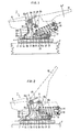
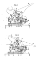
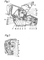
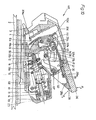
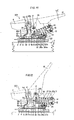
- FIG. 1 to 4 show a first exemplary embodiment, FIG. 1 showing the safety ski binding in a side view in section in the downhill position, FIGS. 2 and 3 each showing the safety ski binding in a position during an arbitrary opening likewise in a side view in section and FIG. 4 are the open position of the safety ski binding after arbitrary opening or after a safety release; 5 to 8 show a second embodiment of a safety ski binding according to the invention, which in turn essentially correspond to FIGS. 1-4 of the first exemplary embodiment, FIG.
- FIG. 9 shows a further exemplary embodiment of the safety ski binding according to the invention in a side view in section in the downhill position, wherein
- this drawing figure shows only the details modified compared to the second exemplary embodiment
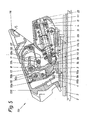
- FIG. 10 shows a further exemplary embodiment in a position analogous to FIGS. 1 and 5
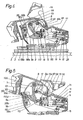
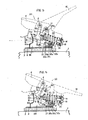
- FIGS. 15 and 16 show a further embodiment of the invention in a modification of the exemplary embodiment according to FIG 11-14 with an additional opening spring, with FIG. 15 a detail of the side view similar to FIG. 11 and FIG. 16 a top view of the arrangement of the two springs.
- the safety ski binding is designed as a heel holder designated in its entirety by 1.
- the heel holder 1 has a guide rail 3 fastened on the upper side of a ski 2 by means of (not shown) screws, on which a base plate 4 of the heel holder 1 is displaceably guided in the longitudinal direction of the ski 2 and in a known manner to adapt the binding to different long ski boots can be locked in the desired position.
- the heel holder 1 is displaceably guided against the force of at least one thrust spring (not shown) on the guide rail 3, the thrust spring being ski-proof on one end and on the base plate 4 of the heel holder 1 in itself is supported in a known manner.
- a bearing block 5 is fastened on the base plate 4 and carries a pivot axis 7 on its rear region adjacent to the base plate 4, on which a sole holder 6 is pivotably mounted.
- the sole holder 6 carries on its upper area on a further axis 8 running parallel to the first-mentioned axis a likewise pivotable latching rocker 9, which extends essentially downward and has a latching projection 9a at its lower end, which according to the heel holder 1 is in the downward position Fig.l trained on the bearing block 5, engages under catch 10.
- the locking part 12 is acted upon by one end of a release spring 13, the other end of which is supported on a spring abutment 14 which is adjustable in the axial direction of the release spring 13 by means of a screw 15 rotatably mounted in the spring housing 11.
- a locking pan 9b is formed for receiving the locking part 12, into which the latter is pressed in the downward position by the release spring 13.
- an opening in the form of a recess 9c is provided on the locking rocker 9, into which the locking part 12 snaps briefly during the actuation of a release lever 16 in a manner to be described.
- the release lever 16 also overlaps the sole holder 6 and is pivotally mounted on the axis 8 arranged on the sole holder 6, on which axis 8 the locking rocker 9 is also articulated.
- a bolt 17 fastened to the release lever 16 parallel to the axis 8 passes through both the sole holder 6 and the side walls of the spring housing 11 and is slidably guided in these two components in elongated holes 6b and 11b, respectively.
- the two are on the sole holder 6 provided slots 6b arranged concentrically to the pivot axis 8; the two elongated holes 11b formed on the spring housing 11 run rectilinearly approximately at right angles to the longitudinal extent of the elongated holes 6b of the sole holder 6.
- the counter-locking 10 cooperating with the locking rocker 9 is formed on a part of the same which is pulled up at the front end region of the bearing block 5.
- the counter detent 10 viewed from the top of the ski, initially forms a detent surface 10a, which is engaged by the detent projection 9a of the detent rocker 9 in the downward position of the heel holder 1.
- a stop is formed by at least one offset 10d in cooperation with an attachment 6c fastened to the sole holder 6 against the sole holder 6 being pivoted too far when the binding is opened.
- the back surface 10b adjoining the locking surface 10a of the counter-locking 10 is designed as an essentially flat surface which is slightly inclined in the direction of the front jaw, not shown.
- a leg spring 20 is wound around the axis 8 carrying the locking rocker 9, the two free end regions of which point towards the end of the ski, one end of the leg spring 20 being supported on the bolt 17 and the other end on the underside of the upper cover of the sole holder 6 .
- an opening spring 21 is furthermore mounted on one side of the binding in the area between the spring housing 11 and on the bearing block 5, which is attached at one end to the base plate of the bearing block 5 and at the other end to one on the sole holder 6, is supported in the binding interior pointing stop 22.
- the mode of operation of the heel holder 1 in question is as follows: If a ski shoe (not shown), which is inserted into the binding, acts on the sole holder 6 in the vertical direction, the sole holder 6 pivots upward about its pivot axis 7. During this pivoting movement, the latching rocker 9 slides along the latching surface 10a of the counter-latch 10 fixed on the bearing block and presses the locking part 12 back against the force of the release spring 13 in the longitudinal slots 11a of the spring housing 11. During the pivoting movement of the sole holder 6, the spring housing 11 is also pivoted about the pivot axis 7 in the same way, so that the locking rocker 9 remains under the action of the release spring 13.
- the sole holder 6 pivots supported by the opening spring 21 arranged on the pivot axis 7 into its open position. In this way, the release spring 13 can relax until the locking part 12 strikes the end regions of the longitudinal slots 11a of the spring housing 11 facing the locking rocker 9.
- the binding is now in its ready-to-go position, which is shown in FIG. The binding is closed from this position simply by depressing the sole holder 6 into the position shown in FIG.
- the release lever 16 is pivoted up in the direction of the arrow F 1 shown in FIG. 1 , for example by hand.
- the spring housing 11 is pivoted upward about the pivot axis 7 by the bolts 17 pivoted upward in the elongated holes 6b, which extend concentrically with the axis 8, the locking part 12 being moved out of the locking recess 9b of the locking rocker 9 against the force of the spring 13.
- the recess 9c of the latching rocker 9 adjoining the latching recess 9b in turn allows the release spring 13 to relax (see FIG.
- the heel holder 101 differs from the one previously described in that the pivot axis 107 carrying the sole holder 106 is arranged on the upper region of the bearing block 105. Furthermore, a further axis 19, which also runs transversely to the longitudinal direction of the ski, is arranged for mounting the spring housing 111 at the rear end region of the bearing block 105.
- the locking part 112 is here wedge-shaped at one end and has a flange-like extension on its area facing away from the wedge-shaped area, on which a spring plate 18 is seated, on which the release spring 13 is supported.
- the bolt 17 passes through an approximately arch-shaped link guide 11 provided on a tab-like extension of the spring housing 111.
- the opening spring 120 acting on the sole holder 106 is provided in an upper end area of the counter catch 110 Recess arranged, one end of the sole holder 106 and the other on Bearing bracket 105 supported.
- the stop limiting the swiveling-up movement of the sole holder 106 is formed by a shoulder 106c fastened to the sole holder 106.
- leg spring 120 acting on the sole holder 106 on the one hand and the unit formed from the spring housing 111 and the release lever 116 on the other hand is mounted on the pivot axis 107 of the sole holder 106 fastened to the bearing block 105.
- the cover 23 thus pivots together with the spring housing 111.
- the cover 23 is equipped with a window provided with a scale, which is provided for displaying the set spring preload. Since this training is known per se, the window is not shown separately in the drawing figures.
- FIGS. 6-8 in turn representing the positions corresponding to FIGS. 2-4 of the first exemplary embodiment.
- the opening spring which brings the heel holder 101 into its ready-to-enter position after an arbitrary opening can now, as shown in FIG. 9, on the axle 8 carrying the locking rocker 9, in a modification of the second embodiment, but following the first embodiment be.
- the spring is designed as a leg spring 20, which is wound around the axis 8 and the two free end regions of which also point towards the end of the ski on the bolt 17 from above and on the sole holder 6 are supported from below.
- the function of this embodiment corresponds to that shown in FIGS. 1 to 4 and 5 to 8. For this reason, the presentation and description of further details is unnecessary.
- the heel holder is therefore ready to be climbed in after an arbitrary opening and can be closed simply by inserting the ski boot into the sole holder. Closing the sole holder by hand is also possible by pressing it down, although a relatively large force has to be overcome. In all the design variants described so far, however, it is also possible to bring the heel holder into its closed position with a considerably lower effort. For this purpose, starting from the position shown in FIGS. 4 and 8, the release lever 116 is pivoted up until the locking part 12 in turn comes out of the locking pan 9b of the locking rocker 9. As shown in a comparison of FIG. 4 with FIG. 3 or FIG. 8 with FIG. 7, this actuation only takes place against the low force of the leg spring 20, 120.
- the sole holder 6, 106 is then brought into its closed position by hand, only the release spring 13, which has a force of the opening spring 21, 121 to be overcome, being overcome. Due to the release lever 116 now pivoted, for example, by hand again in the closing direction, the locking part 12 again engages in the locking pan 9b of the locking rocker 9, the trigger spring 13 being compressed only slightly when this actuation is carried out. In this way, the heel holder can be brought into its closed position by hand with less effort. This procedure will be chosen especially when the heel holder is to be closed for the transport of the skis. This procedure for closing the heel holder is also advantageous for the binding fitter when adapting the binding to the ski boot length.
- the heel holder 201 shown in FIG essential to that according to FIGS. 5 to 8.
- the sole holder 206 is made higher than in the exemplary embodiments according to FIGS. 5-8 or 9, so that in the region between the locking rocker 9 and the upper cover of the sole holder 206, a pivoting movement of a slide 28 fastened to the release lever 216 is described in more detail can take place unhindered.
- an elongated hole 26 is provided, which elongated holes 26 are penetrated by the axis 8 which is mounted on the sole holder 206 and carries the locking rocker 9 and which are concentric to the pivot axis 107.
- the axis 8 is in each case at the upper end region of the elongated holes 26.
- the release lever 216 is supported from above via its two side walls on the pivot axis 107 of the sole holder 206.
- the respective support region of the release lever 216 as shown in FIG. 10, can be curved in accordance with the radius of the pivot axis 107.
- the bolt 17 fastened to the release lever 216 now passes through a recess 27 formed on the side regions of the sole holder 206.
- the recesses 27 replace the elongated holes 6b of the preceding exemplary embodiments.
- the boundary edge of each recess 27 facing the axis 8 is rounded concentrically to the pivot axis 107, the boundary edge of each recess 27 facing the pivot axis 107 is rounded concentrically to the axis 8.
- the slide 28 On the underside of the release lever 216, the slide 28 is mounted so that it can be displaced in the longitudinal direction of the release lever 216.
- one or more guide tabs 29, which hold the slide 28 on the underside of the release lever 216 can be provided.
- the slide 28 itself extends approximately over the entire length of the release lever 216 and is over its end region in the direction of Sole holder 206 extended above the locking rocker 9.
- the slide 28 passes through a recess 206d in the upper cover of the sole holder 206 in the longitudinal direction of the ski.
- the slider 28 carries a hook-like gripping element 28a which, in a manner to be described, is provided for encompassing the axle 8 mounted in the sole holder 206.
- the detent rocker 9 and the counter detent 10 are to be provided in the center with corresponding recesses, not specified.
- the slide 28 is held in its position shown in FIG. 10, in which the gripping element 28a is in front of the axis 8, by a spring 30.
- the spring 30 is designed as a compression spring and is arranged in a cutout in the slide 28, is supported at one end on the slide 28 and at the other end on a support projection 216a of the release lever 216 which projects into the recess of the slide 28.
- the slide 28 is provided with an actuating projection 28b for gripping by hand.
- This heel holder can now be opened arbitrarily either by pulling on or by pressing the release lever 216.
- the release lever 216 When opened by pulling the release lever 216 in the direction of arrow F 2 in FIG. 10, the release lever 216 is supported on the axis 8, which now acts as a pivot axis for the release lever 216.
- An unobstructed pivoting movement of the release lever 216 with the slide 28 is made possible by the recess 206d in the sole holder 206, so that the sole holder 206 can be opened in the manner described in the first exemplary embodiment according to FIGS.
- the release lever 216 is pivoted downward in the direction of the arrow F 3 in FIG.
- the release lever 216 is supported on the pivot axis 107 fixed to the bearing block, about which both the sole holder 206 and the release lever 216 are now pivoted.
- Those mounted between the release lever 216 and the one on the sole holder 206 Axial 8 relative movement is made possible by the two elongated holes 26 in the trigger lever 216.
- the bolt 17 fastened to the release lever 216 is pivoted up, this movement being made possible by the two recesses 27 in the sole holder 206.
- the spring housing 111 is also pivoted up about the axis 19 via the bolt 17, the locking part 12 being released against the force of the release spring 13 from the locking pan 9b of the locking rocker 9 and then, as already described in the previous exemplary embodiments, into the region of the recess 9c the locking rocker 9 arrives.
- the sole holder 206 After releasing the release lever 216, the sole holder 206 begins to pivot (either by lifting the ski boot inserted into the sole holder 206 or supported by the opening spring 221) about the pivot axis 107; at the same time, the locking rocker 9 swings somewhat backwards and the axis 8 carrying the locking rocker 9 slides somewhat upward in the elongated holes 26.
- the locking rocker 9 sliding backwards along the counter-locking 10 detects the locking part 12, which is now pivoted along the locking rocker 9 together with the spring housing 111 upwards about the axis 19.
- the bolt 17 fastened to the trigger lever 216 also pivots upward, the trigger lever 216 simultaneously about the axis 8, which now represents the new pivot axis of the trigger lever 216, in the direction of the arrow F 2 in FIG. 10 (i.e. in the opposite direction) Direction to print direction) pivots upwards.
- the detent rocker 9 can now pivot past the counter-detent 10 with the sole holder 206 upward.
- the leg spring 220 which is supported on one end on the sole holder 206 and on the other side on the bolt 17 and which has been prestressed during the movement sequences just described, comes into effect and presses the bolt 17 and thus the spring housing 111 down, as a result of which the locking part 12 slides back into the locking pan 9b of the locking rocker 9.
- This also the release lever 216 carrying the bolt 17 is brought into its closed position so that the heel holder 201 is now in its ready-to-go position.
- the heel holder 201 which is now ready for boarding, can be closed again by depressing the sole holder 206. However, in order to be able to close the sole holder 206 by hand with less effort, the slide 28 is provided.
- the slider 28 is gripped by hand and pulled against the force of the weak spring 30 in the direction away from the sole holder 206.
- the hook-like gripping element 28a grips the axis 8, so that the two elongated holes 26 are now ineffective.
- the release lever 216 is now pivoted up until the locking part 12 in turn comes out of the locking pan 9b of the locking rocker 9. This actuation only takes place against the low force of the leg spring 120.
- the sole holder 206 is then brought into its closed position by hand, only the force of the opening spring 121 having to be overcome.
- the trigger lever 216 is pivoted by hand with the slider 28 still actuated in the closing direction, the locking part 12 again engaging in the locking pan 9b of the locking rocker 9. Although this engagement takes place against the force of the release spring 13, much less effort is required than by simply closing the sole holder 206.
- a resilient catch for the slider 28 can be provided on the release lever 216, which latches in a corresponding latching recess during the actuation of the slider 28.
- An automatic unlatching of the slide 28 is possible, for example, by designing the actuation area of the slide 28 as a separate component, which is designed as a two-armed lever articulated on the slide 28, the lever of which a lever arm carries the actuating shoulder and is acted upon by a further spring in the direction of the underside of the release lever 216 and whose second lever arm points away from the underside of the release lever 216.
- This second lever arm can now strike, for example, the pivot axis 107 during the depression of the trigger lever 216, as a result of which the lever is pivoted and the latching is released automatically. 4th
- a slide can be provided with two lateral support tabs which can be brought under the axis 8 by actuating the slide on the side of the locking rocker and support it from below.
- the support tabs provided at the end region of the slider, viewed in the downward position of the heel holder according to FIG. It is therefore necessary to move the slide towards the sole holder.
- gripping elements can also be provided, which are in the unactuated position of the slide in the area behind the axis 8 of the locking rocker 9 and can be pushed laterally on the axis 8 of the locking rocker 9.
- FIGS. 11-14 shows a heel holder 301 with a further modification of the design and arrangement of the leg spring 320.
- This is wound around the common pivot axis 7 of the sole holder 6 and spring housing 11, the free end regions of both legs of the leg spring 320 pointing forward, towards the sole holder 6, and the Leg spring 320, viewed in the driving position, is supported with one of its legs 320b on a bearing block fixed to a bearing block 305a and with its other leg 320a on a stop projection 22 attached to the sole holder 6.
- the two legs 320a, 320b intersect, as shown in particular in FIG. 11, in the projection onto the plane of the drawing.
- the spring housing 311 also has a stop 311c, which is located in this position of the heel holder 301 in the vicinity of the base plate 4, at a distance from the leg 320b of the leg spring 320 which is supported on the bearing block fixed stop 305a.
- the stop 311c of the spring housing 311 can be swiveled up in the plane in which the leg 320b of the leg spring 320 which is supported or can be supported on the bearing block fixed to the bearing block lies.
- the leg spring 320 fulfills, as will be explained on the occasion of the function of the heel holder 301, both the function of an opening spring and that of a return spring.
- the mode of operation of the heel holder 301 corresponds to an involuntary triggering process, e.g. bie a fall of the skier, that of the embodiment of FIGS. 1-4.
- the release lever 16 is pivoted upward, for example by hand, in the direction of the arrow F1 shown in FIG.
- the spring housing 311 is pivoted upward about the axis 7 by the bolts 17 pivoted upward in the elongated holes 6b, which extend concentrically to the axis 8, the locking part 12 being moved out of the locking recess 9b of the locking rocker 9 against the force of the spring 13.
- This unlatching allows the recess 9c of the locking rocker 9 adjoining the locking recess 9b in turn to relax the release spring 13 (see FIG.
- leg spring 320 acting as an opening spring can pivot so far that it slides upward along the counter-latch 10.
- FIG. 13 shows the heel holder 301 in a position with the sole holder 6 not yet fully pivoted up, the latching rocker 9 being in an intermediate position on the counter-latch 10 and the leg 320b of the leg spring 320 having been somewhat removed from the bearing block-fixed stop 305a.
- the spring housing 311 While the spring housing 311 has reached this predetermined, obliquely upward-pointing position, the leg 320b of the leg spring 320 supported in the travel position on the bearing block fixed stop 305a of the leg spring 320 was lifted off the stop 305a by means of the stop 311c attached to the spring housing 311, so that the leg spring 320 now Sole holder 6 and the spring housing 311 in opposite directions, etc. with one of the original preload against increased clamping force.
- the sole holder 6 takes the locking rocker 9 with it, the latter can pivot about its axis 8 between the back surface 10b of the bearing block-fixed counter-locking 10 and the locking part 12 of the spring housing 311 free of any spring force or level off.
- the latching rocker 9 is guided along the back surface 10b of the counter-latch 10 fixed on the bearing block.
- the course of the back surface 10b of the counter detent 10 is selected so that in the last phase of the
- a further leg spring 421 is mounted on the pivot axis 7 of the sole holder 6 of the heel holder 401, with one of its legs 421b on the base plate of the bearing block 305 and with its other leg 421a on the attached to the sole holder 6, in the binding interior pointing stop 22 is supported.
- This leg spring 421 acts exclusively as an opening spring.
- the first phase of the arbitrary opening it supports the effectiveness of the (first) leg spring 320 acting in the opening direction of the sole holder 6, which is to prevent the heel holder 401 from swinging up properly or not completely in the event of icing or under unfavorable slope conditions, as a result of which Similar difficulties could arise as they were mentioned as a certain disadvantage in the configuration according to the first exemplary embodiment (on page 6, paragraph 2).
- the force of the leg spring 421 acting as the opening spring is greater than that of the double function, i.e. both opening and resetting, exercising leg spring 320, so that the latter always experiences a kind of support on the sole holder 6.
- the further structure of this heel holder 401 corresponds to that of the heel holder 301 described with reference to FIGS. 11 to 14.
- the mode of operation of the heel holder 401 according to FIGS. 15 and 16 differs from that of the heel holder 301 insofar as the additional leg spring 421 as described Sole holder 6 is acted upon during the entire course of the arbitrary opening in the opening direction and thus for resetting the spring housing 311 and the release lever 16 by means of the (first) leg spring 320 in the second phase of the arbitrary opening through the sole holder-fixed stop shoulder 22 for the one leg 320a of the latter spring (320) forms a defined support.
- the invention is not restricted to the exemplary embodiments shown. Further modifications are conceivable without leaving the scope of the scope of protection. So it is particularly possible to pivot the bearing block on a vertical axis to be attached to the base plate in the horizontal plane and at the same time to provide a control curve at the front end region of the base plate, which cooperates with a counter-catch arranged on the sole holder, so that a so-called diagonal release control given is. Since the measures required for this are known per se, the details in this regard were not dealt with in the description. Furthermore, it is conceivable to arrange the leg spring on an additional bolt mounted on the sole holder.
- leg spring instead of the leg spring, which is also supported at one end on the sole holder and at the other preferably on the bolt coupling the spring housing to the release lever.
- the spring could also be supported on the spring housing itself.
- the arrangement of such a spring is also possible with a binding system in which the release spring is arranged in a cavity of the release lever itself. In this case, it is then possible, for example, to support the spring on a part of the release lever in such a way that it is acted upon in the closing direction, as a result of which the spring part of the spring housing reaches the region of the latching recess of the latching rocker.
- sole holder The component which serves to hold the ski boot and can be swiveled up about the pivot axis fixed to the bearing block was referred to as such a "sole holder".
- this designation not only applies to the actual sole holder (in the narrower sense) used to hold down the heel of the ski boots, if necessary with a conventional step spur serving to get in, but also the area generally covering the bearing block in the driving position, generally referred to as the housing, on which the sole holder is fastened or articulated, in this context, it should be pointed out that construction pieces designated as sole holder fixed also include an arrangement fixed to the housing.
- the force of the additional spring is lower, preferably substantially lower, than the force of the opening spring acting on the sole holder.
Landscapes
- Footwear And Its Accessory, Manufacturing Method And Apparatuses (AREA)
Abstract
Die Erfindung betrifft einen Fersenhalter (1) für Sicherheitsskibindungen, der mit einem um eine in einem Lagerbock (5) gelagerte Queraschse (7) hochschwenkbaren Sohlenhalter (6) versehen ist. Der Sohlenhalter (6) trägt eine parallel zur Querachse (7) verlaufende Achse (8), an welcher eine Ratschwinge (9) angelenkt ist. Diese untergreift in der Fahrtstellung eine Gegenrast (10) des Lagerbocks (5) und ist aus dieser Lage bei Überlast gegen die Kraft einer einstellbaren Auslösefeder (13) entrastbar. Die Auslösefeder (13) ist in einem an einer lagerbockfesten Achse (19), die gegebenenfalls die Querachse (7) ist, schwenkbar gelagerten Federgehäuse (11) untergebracht. Das Federgehäuse (11) ist über einen Bolzen (17) mit einem Auslösehebel (16) gelenkig verbunden, welcher Auslösehebel (16) in bekannter Weise zum willkürlichen Aussteigen aus dem Fersenhalter (1) mit einem Skischuh dient. Der Auslösehebel (16) ist hiezu an einer der Achsen angelenkt. Der Sohlenhalter (6) steht unter dem Einfluß einer ihn in Öffnungsrichtung beaufschlagenden Feder (21). Erfindungswesentlich ist die Verwendung einer Feder (20), welche zumindest in einer Phase des willkürlichen Aussteigens das Federgehäuse (11) bzw. den Auslösehebel (16) in Schließrichtung und den Sohlenhalter (6) in Öffnungsrichtung beaufschlagt.The invention relates to a heel holder (1) for safety ski bindings, which is provided with a sole holder (6) which can be swiveled up around a crossbar (7) mounted in a bearing block (5). The sole holder (6) carries an axis (8) which runs parallel to the transverse axis (7) and to which a ratchet arm (9) is articulated. In the driving position, this engages under a counter detent (10) of the bearing block (5) and can be released from this position in the event of an overload against the force of an adjustable release spring (13). The release spring (13) is accommodated in a spring housing (11) which is pivotably mounted on an axle (19) which is fixed to the bearing block and which is possibly the transverse axis (7). The spring housing (11) is connected in an articulated manner via a bolt (17) to a release lever (16), which release lever (16) is used in a known manner for arbitrarily getting out of the heel holder (1) with a ski boot. The release lever (16) is articulated on one of the axes. The sole holder (6) is under the influence of a spring (21) acting on it in the opening direction. Essential to the invention is the use of a spring (20), which acts on the spring housing (11) or the release lever (16) in the closing direction and the sole holder (6) in the opening direction at least in a phase of arbitrary getting out.
Description
Die Erfindung betrifft eine Sicherheitsskibindung, insbesondere einen Fersenhalter mit einem an einem Lagerbock um eine Querachse schwenkbaren Sohlenhalter, der durch eine am Sohlenhalter schwenkbar gelagerte Rastschwinge in der Abfahrtsstellung gehalten ist, welche an der einen Seite einen Rastvorsprung aufweist, der in der Abfahrtsstellung eine am Lagerbock angeordnete Rastnase untergreift und an der anderen Seite mit einer Rastvertiefung versehen ist, in die ein von einer Auslösefeder belasteter Sperrteil zumindest in der Abfahrtsstellung eingreift, welcher in einem gegenüber dem Lagerbock schwenkbaren Federgehäuse gelagert und in Führungen desselben begrenzt verschiebbar ist, wobei zum willkürlichen Öffnen des Sohlenhalters ein am Sohlenhalter schwenkbar gelagerter Auslösehebel vorgesehen ist, durch dessen Betätigung das Federgehäuse hochschwenkbar und der Sperrteil aus der Rastvertiefung der Rastschwinge entrastbar ist, so daß die Rastschwinge in dieser (entrasteten) Lage um ihre Achse (kraft)frei verschwenkbar ist und wobei der Sohlenhalter unmittelbar von einer ihn in die Offenstellung zu schwenke trachtenden Öffnungsfeder beaufschlagt ist.The invention relates to a safety ski binding, in particular a heel holder with a sole holder pivotable on a bearing block about a transverse axis, which is held in the downward position by a latching rocker pivotally mounted on the sole holder, which has a latching projection on one side, which in the downward position has a latching bracket Arranged latching nose engages and is provided on the other side with a locking recess into which a locking part loaded by a release spring engages at least in the downward position, which is mounted in a spring housing which can be pivoted relative to the bearing block and can be displaced to a limited extent in guides thereof, with the voluntary opening of the Sole holder a release lever pivotally mounted on the sole holder is provided, by the actuation of which the spring housing can be pivoted up and the locking part can be unlocked from the locking recess of the locking rocker so that the locking rocker is in its (unlocked) position around it Axis (force) can be freely pivoted and the sole holder is acted upon directly by an opening spring which tends to pivot it into the open position.
Eine Sicherheitsskibindung der eingangs genannten Art ist beispielsweise in der DE-OS 28 38 904 (siehe Fig.1 bis 5) beschrieben. Bei dieser bekannten Bindung ist die Feder in einem Hohlraum des am Sohlenhalter schwenkbar gelagerten Auslösehebels angeordnet. Der Auslösehebel bildet somit gleichzeitig das Federgehäuse. Nach einem willkürlichen Öffnen des Sohlenhalters durch Betätigen des Auslösehebels befindet sich diese Bindung jedoch nicht in der einsteigbereiten Stellung. Zum Wiedereinsetzen des Skischuhes bzw. Schließen des Sohlenhalters ist ein zusätzlicher Handgriff erforderlich. Entweder wird zuerst der Auslösehebel durch Ausübung einer Kraft geschlossen, so daß der Sperrteil wieder in der Rastvertiefung der Rastschwinge einschnappt, worauf anschließend der Sohlenhalter durch Niederdrücken geschlossen werden kann. Es ist aber auch möglich, zunächst beispielsweise durch Einsetzen des Skischuhes in die Bindung den Sohlenhalter zu schließen, und erst dann, beispielsweise mittels eines Skistockes, den Auslösehebel in seine Schließlage und somit den Sperrteil in die Rastvertiefung der Rastschwinge zu drücken.A safety ski binding of the type mentioned at the outset is described, for example, in DE-OS 28 38 904 (see FIGS. 1 to 5). In this known binding, the spring is arranged in a cavity of the release lever pivotally mounted on the sole holder. The trigger lever thus forms the spring housing at the same time. After an arbitrary opening of the sole holder by actuating the release lever, however, this binding is not in the ready-for-entry position. An additional handle is required to reinsert the ski boot or close the sole holder. Either the release lever is first closed by exerting a force so that the locking part snaps back into the locking recess of the locking rocker, whereupon the sole holder can then be closed by pressing it down. But it is also possible, for example, first by inserting the ski boot in the binding to close the sole holder, and only then, for example by means of a ski pole, to press the release lever into its closed position and thus the locking part into the locking recess of the locking rocker.
Eine weitere derartige Sicherheitsskibindung ist in der AT-PS 327.068 dargestellt. Diese Bindung hat sich in der Praxis sehr gut bewährt. Bei dieser Bindung ist der Auslösehebel an der Achse der Rastschwinge schwenkbar gelagert und trägt einen Bolzen, der sowohl konzentrisch zur Achse der Rastschwinge beidseitig am Sohlenhalter ausgebildete Langlöcher als auch beidseitig am Federgehäuse ausgebildete Langlöcher durchsetzt. Auch auf diese Weise ist bei einem Betätigen des Auslösehebels ein Freikommen des Sperrteiles aus der Rastvertiefung der Rastschwinge gegeben, wodurch die Rastschwinge von der lagerbockfesten Rastnase freikommt und der Sohlenhalter praktisch frei um seine Schwenkachse hochschwenken kann. Nach einem willkürlichen Öffnen des Sohlenhalters befindet sich diese Fersenbindung jedoch auch nicht in der einsteigbereiten Stellung, ein Wiedereinsetzen des Skischuhes bzw. ein Schließen des Fersenhalters ist auf die beiden weiter oben schon beschriebenen Arten möglich.Another such ski binding is shown in AT-PS 327.068. This bond has proven itself very well in practice. In this binding, the release lever is pivotally mounted on the axis of the locking rocker and carries a bolt which passes through both elongated holes formed concentrically with the axis of the locking rocker on both sides of the sole holder and elongated holes formed on both sides on the spring housing. In this way too, when the release lever is actuated, the locking part is released from the latching recess of the latching rocker, whereby the latching rocker is released from the bearing block which is fixed to the bearing block and the sole holder can pivot up freely about its pivot axis. After an arbitrary opening of the sole holder, however, this heel binding is also not in the ready-for-entry position, a reinsertion of the ski boot or a closing of the heel holder is possible in the two ways already described above.
Die Erfindung hat sich daher die Aufgabe gestellt, eine Sicherheitsskibindung der eingangs genannten Art derart zu gestalten, daß sie sich nach einem willkürlichen Öffnen in der einsteigbereiten Lage befindet.The invention is therefore based on the task of creating a safety ski binding of the type mentioned such that it is located to an arbitrary opening in the einsteigberei t s location.
Gelöst wird die gestellte Aufgabe erfindungsgemäß dadurch, daß wie an sich bekannt, eine weitere, den Auslösehebel bzw. das Federgehäuse mit dem Sperrteil in Schließrichtung beaufschlagende Feder vorgesehen ist, daß diese Feder als eine Schenkelfeder ausgebildet ist, die den Sohlenhalter einerseits und den Auslösehebel bzw. das Federgehäuse mit dem Sperrteil anderseits, zumindest in einer Phase des willkürlichen Auslösens, gegensinnig beaufschlagt, wobei nach erfolgtem willkürlichen Öffnen des Sohlenhalters die Rastschwinge von dem sich schließenden, jurch die Schenkelfeder beaufschlagten Sperrteil an die lagerbockfeste Gegenrast geschwenkt gehalten wird, bis der Sperrteil wieder in der Rastvertiefung der Rastschwinge zum Liegen kommt.The object is achieved according to the invention in that, as is known per se, a further spring acting on the release lever or the spring housing with the locking part in the closing direction is provided in that this spring is designed as a leg spring which holds the sole holder on the one hand and the release lever or on the other hand, the spring housing with the locking part, at least in a phase of arbitrary triggering, is acted on in opposite directions, with the locking rocker being released from the closing after the sole holder has been opened voluntarily. is held pivoted by the leg spring locking part to the bearing block-fixed counter-locking until the locking part comes to rest again in the locking recess of the locking rocker.
Die an erster Stelle genannte Merkmalsgruppe ist zwar aus der CH-PS 500.730 für sich bekannt, allerdings in einer Ausführungsform, bei der die Rastschwinge dauernd unter der Wirkung der Auslösefeder steht, ja sogar während des willkürlichen Auslösens die Federkraft noch stärker überwunden werden muß als dies während eines unwillkürlichen Auslösens der Fall ist, weil die Stützfläche der dort gezeigten Rastschwinge schräg nach oben verläuft. Dazu kommt, daß der Sohlenhalter mit der die beiden Aussparungen voneinander trennenden Nase zusätzlich gegen die Kraft der Auslösefeder verschwenkt werden muß, die selbst dann, wenn sich der Auslösehebel samt Auslösefeder nach Fig.3 in der Obertotpunktlage befindet. Für die Betätigung des Sohlenhalters ist eine gesonderte öffnungsfeder vorhanden; zwischen der Betätigung des Sohlenhalters und der des Federgehäuses besteht keine Zwangssteuerung. Durch diese weitere, den Erfindungsgegenstand kennzeichnende Maßnahme wird einerseits ein begünstigtes Öffnen des Sohlenhalters herbeigeführt, andererseits das Zusammenführen von Rastschwinge und Federgehäuse bewerkstelligt, so daß der Fersenhalter wieder in die Einsteigsbereitschaftsstellung gelangt. Diese Vorgangsweise erfolgt somit nach Loslassen des Auslösehebels und nach erfolgtem vollständigen Öffnen des Sohlenhalters vollautomatisch. Hiedurch wird der Bedienungskomfort der bekannten Bindungen, deren Vorteile die erfindungsgemäße Bindung ebenfalls aufweist, wesentlich verbessert.The group of features mentioned in the first place is known per se from CH-PS 500.730, but in an embodiment in which the locking rocker is constantly under the action of the release spring, and even during the arbitrary release the spring force has to be overcome even more than this during an involuntary release, because the support surface of the locking arm shown there runs obliquely upwards. In addition, the sole holder with the nose separating the two recesses must also be pivoted against the force of the release spring, which is even when the release lever together with the release spring according to FIG. 3 is in the top dead center position. There is a separate opening spring for operating the sole holder; there is no positive control between the actuation of the sole holder and that of the spring housing. This further measure, which characterizes the subject matter of the invention, on the one hand brings about a favorable opening of the sole holder, and on the other hand brings the locking rocker and spring housing together, so that the heel holder returns to the ready-for-entry position. This procedure takes place fully automatically after releasing the release lever and after fully opening the sole holder. This significantly improves the ease of use of the known bindings, the advantages of which the binding according to the invention also has.
Bildet der Auslösehebel gleichzeitig das Federgehäuse, so ist es vorteilhaft, wenn erfindungsgemäß die (weitere) Schenkelfeder an der die Rastschwinge tragenden Achse gelagert ist und einerends am Sohlenhalter und anderends am Federgehäuse bzw. am Auslösehebel abgestützt ist. Bei dieser Ausführungsform sind daher keine zusätzlichen Bauteile zur Unterbringung und Anordnung der (weiteren) Schenkelfeder erforderlich. Eine weitere bevorzugte Ausführungsform der Erfindung für eine Bindung, bei der die Schwenkachse des Sohlenhalters im hinteren sowie der Grundplatte benachbarten Bereich der Bindung vorgesehen ist, wobei das Federgehäuse vorzugsweise ebenfalls an der Schwenkachse des Sohlenhalters gelagert ist und dieses mit dem Auslösehebel über eine gleitbeweglich gelagerte Gelenkverbindung, beispielsweise über einen an diesem befestigten Bolzen, welcher in einer durch ein Langloch gebildete Führung des Federgehäuses gleitbeweglich gelagert ist, gekoppelt ist, besteht darin, daß die Schenkelfeder an der die Rastschwinge tragenden Achse gelagert ist und einerends am Sohlenhalter und anderends an dem das Federgehäuse mit dem Auslösehebel koppelnden Bolzen abgestützt ist. Dadurch gestaltet sich eine Unterbringung der Schenkelfeder in einem Bindungssystem, wie es in der vorangehend beschriebenen AT-PS 327.068 gezeigt ist, besonders einfach.If the release lever forms the spring housing at the same time, it is advantageous if, according to the invention, the (further) leg spring is mounted on the axis carrying the locking rocker and is supported on one side on the sole holder and on the other side on the spring housing or on the release lever. In this embodiment, therefore, no additional components for accommodating and arranging the (further) leg spring are required. Another preferred embodiment of the invention for a binding, in which the pivot axis of the sole holder is provided in the rear and the base plate adjacent region of the binding, the spring housing is preferably also mounted on the pivot axis of the sole holder and this with the release lever via a slidably articulated connection , for example via a bolt attached to it, which is slidably mounted in a guide of the spring housing formed by an elongated hole, is that the leg spring is mounted on the axis carrying the locking rocker and one end on the sole holder and the other on the spring housing is supported with the coupling lever coupling pin. This makes it particularly easy to accommodate the leg spring in a binding system, as shown in AT-PS 327.068 described above.
Ein weiteres Merkmal der Erfindung, bei der die Schwenkachse des Sohlenhalters im oberen Bereich des Lagerbockes angeordnet ist, besteht darin, daß die Schenkelfeder entweder an der Schwenkachse des Sohlenhalters oder an der die Rastschwinge tragenden Achse gelagert ist, einerends an dem den Auslösehebel mit dem Federgehäuse koppelnden Bolzen von oben her und anderends von unten her am Gehäuse des Sohlenhalters abgestützt ist. In beiden Fällen sind keine wesentlichen baulichen Änderungen am Fersenhalter zur Unterbringung und Anordnung der zusätzlichen Feder erforderlich.Another feature of the invention, in which the pivot axis of the sole holder is arranged in the upper region of the pedestal, is that the leg spring is mounted either on the pivot axis of the sole holder or on the axis carrying the locking rocker arm, one end on which the release lever with the spring housing coupling bolt is supported from above and elsewhere from below on the housing of the sole holder. In both cases, no significant structural changes to the heel holder are required to accommodate and arrange the additional spring.
Eine Weiterentwicklung der Erfindung besteht darin, daß die die Rastschwinge tragende Achse in zwei an den Seitenwänden des Auslösehebels konzentrisch zur Schwenkachse des Sohlenhalters verlaufenden Langlöchern gelagert ist, daß sich der Auslösehebel an der Schwenkachse des Sohlenhalters von oben her abstützt, und daß der Sohlenhalter für den am Auslösehebel befestigten Bolzen je eine Freistellung in Form einer Ausnehmung aufweist. Durch diese erfindungsgemäßen Maßnahmen ergibt sich die Möglichkeit, den Fersenhalter sowohl durch Drücken auf den als auch durch Ziehen am Auslösehbel willkürlich zu öffnen. Bei einer Zugöffnung wirkt die die Rastschwinge tragende Achse als Schwenkachse des Auslösehebels, bei einer Drucköffnung wirkt die Schwenkachse des Sohlenhalters gleichzeitig als Schwenkachse für den Auslösehebel, wobei in diesem Fall die Relativbewegung zwischen der die Rastschwinge tragenden Achse und dem Auslösehebel durch die beiden Langlöcher im Auslösehebel ermöglicht wird. In beiden Fällen befindet sich der Fersenhalter nach einem willkürlichen Öffnen in der einstiegsbereiten Lage.A further development of the invention is that the axis carrying the locking rocker is mounted in two oblong holes running concentrically to the pivot axis of the sole holder on the side walls of the release lever, that the release lever is supported on the pivot axis of the sole holder from above, and that the sole holder for the bolt attached to the release lever each has an exemption in the form of a recess. Through these measures according to the invention, there is the possibility of pressing the heel holder both by pressing on the can also be opened arbitrarily by pulling the release lever. In the case of a pull opening, the axis carrying the locking rocker acts as the pivot axis of the release lever; in the case of a pressure opening, the pivot axis of the sole holder also acts as the pivot axis for the release lever, in which case the relative movement between the axis carrying the locking rocker and the release lever through the two elongated holes in the release lever is made possible. In both cases, the heel holder is in the ready-to-go position after an arbitrary opening.
Bei dieser Ausführungsform der Erfindung ist es vorteilhaft, wenn die Abstützbereiche des Auslösehebels an der Schwenkachse des Sohlenhalters dem Radius derselben entsprechend abgerundet sind. Dadurch ergibt sich eine günstige Kräfteverteilung bei einer Drucköffnung.In this embodiment of the invention, it is advantageous if the support areas of the release lever on the pivot axis of the sole holder are rounded according to the radius of the same. This results in a favorable distribution of forces in a pressure opening.
Um nun bei dieser Ausführungsform ein Schließen des Sohlenhalters aus seiner Offenstellung mit einem geringen Kraftaufwand bewerkstelligen zu können, ist nach einem weiteren Merkmal der Erfindung vorgesehen, daß der durch die beiden Langlöcher im Auslösehebel bestimmte Schwenkbereich desselben mittels einer willkürlich betätigbaren Sperre außer Wirkung setzbar ist. Dadurch ist es möglich, bei wirksamer Sperre ein Schließen des Fersenhalters mit geringem Kraftaufwand, wie schon erwähnt wurde, zu bewerkstelligen.In order to be able to close the sole holder from its open position with little effort in this embodiment, it is provided according to a further feature of the invention that the pivoting range determined by the two elongated holes in the release lever thereof can be deactivated by means of an arbitrarily actuated lock. This makes it possible, with an effective lock, to close the heel holder with little effort, as has already been mentioned.
Diese Sperre kann nun erfindungsgemäß von einem am Auslösehebel in der Längsrichtung desselben verschiebbar gelagerten, federbelasteten Schieber gebildet sein, der einerends einen von Hand erfaßbaren Betätigungsansatz und anderends zumindest ein hakenförmiges Greifelement aufweist, welches durch ein Betätigen des Schiebers die Achse der Rastschwinge umfaßt.This lock can now be formed according to the invention by a spring-loaded slide which is displaceably mounted on the release lever in the longitudinal direction thereof and which has on one end a manually detectable actuating projection and on the other hand has at least one hook-shaped gripping element which, by actuating the slide, comprises the axis of the locking rocker.
Eine weitere leicht unterzubringende Sperre kann von einem am Auslösehebel in der Längsrichtung desselben verschiebbar gelagerten, federbelasteten Schieber gebildet sein, der einerends einen von Hand erfaßbaren Betätigungsansatz aufweist und anderends gabelförmig geteilt ist und zwei Stützelemente trägt, die seitlich der Rastschwinge verlaufen und durch ein Betätigen des Schiebers unter die Achse der Rastschwinge bringbar sind und diese von unten her abstützen.A further lock that can be easily accommodated can be provided by a spring-loaded spring that is displaceably mounted on the release lever in the longitudinal direction thereof Loaded slide be formed, which has a hand-detectable actuation approach on one end and is forked on the other and carries two support elements that extend to the side of the locking rocker and can be brought under the axis of the locking rocker by actuating the slide and support it from below.
Die Erfindung hat sich weiters auch die Aufgabe gestellt, Maßnahmen zu treffen, daß die Bindung sich nach einem willkürlichen Öffnen immer in einer genau definierten Lage, nämlich entweder in der entrasteten oder in der einsteigbereiten Lage befinden soll, und es zu keinem Verklemmen zwischen dem Steg des Federgehäuses in dessen entrasteter Lage mit der Rastschwinge durch unsachgerechtes Betätigen, insbesondere zufolge frühzeitiger Freilassen des Auslösehebels, kommen kann.The invention also has the task of taking measures that the binding is always in a precisely defined position after an arbitrary opening, namely either in the unlocked or in the ready-to-go position, and there is no jamming between the web of the spring housing in its unlocked position with the locking rocker due to improper actuation, in particular due to early release of the release lever.
Zur Lösung dieser weiteren Aufgabe wird erfindungsgemäß vorgesehen, daß die Schenkelfeder an der Schwenkachse des Sohlenhalters mit nach vorn (in der Richtung des Sohlenhalters) weisenden und, im Aufriß und in der Projektion auf die Zeichnungsebene betrachtet, sich kreuzenden Schenkeln angeordnet ist, wobei, in der Fahrtstellung und in der ersten Phase des willkürlichen Öffnens betrachtet, der nach unten weisende Schenkel an einem Anschlag des Sohlenhalters von unten her und der nach oben weisende Schenkel an einem lagerbockfesten Anschlag von oben her abgestützt ist, so daß die Schenkelfeder als Öffnungsfeder wirksam ist, und daß das Federgehäuse ebenfalls einen Anschlag aufweist, welcher in der Ebene des am lagerbockfesten Anschlag abgestützten Schenkels der Schenkelfeder verschwenkbar ist und welcher in dieser Lage des Sohlenhalters, in Höhenrichtung betrachtet, in einem Abstand unterhalb des genannten Schenkels der Schenkelfeder liegt, wobei dieser Anschlag in der zweiten Phase des willkürlichen Öffnens, in welcher sich der Steg in seiner von der Rastvertiefung der Rastschwinge entrasteten Lage befindet, am genannten Schenkel anliegend diesen vom lagerbockfesten Anschlag abhebt und ab dieser Phase des willkürlichen Öffnens das Federgehäuse in seine Schließstellung mit der Rastschwinge drängt, so daß die Schenkelfeder als Rückstellfeder wirksam ist.To solve this further problem, the invention provides that the leg spring is arranged on the pivot axis of the sole holder with forward (in the direction of the sole holder) and, viewed in elevation and in the projection onto the plane of the drawing, crossing legs, wherein, in the driving position and in the first phase of arbitrary opening, the leg pointing downward is supported from below on a stop of the sole holder and the leg pointing upward is supported on a bearing block-fixed stop from above, so that the leg spring acts as an opening spring, and that the spring housing also has a stop which is pivotable in the plane of the leg of the leg spring supported on the bearing block fixed stop and which, viewed in the vertical direction, lies in this position of the sole holder at a distance below the leg of the leg spring, this stop in the second phase of arbitrary opening, in which the web is in its position unlatched from the locking recess of the locking rocker, abuts against the mentioned leg from the bearing block-fixed stop and from this phase of arbitrary opening the Pushes the spring housing into its closed position with the locking rocker so that the leg spring acts as a return spring.
Dadurch, daß der Sohlenhalter einerseits und der Auslösehebel bzw. das Federgehäuse anderseits von der Schenkelfeder erfindungsgemäß gegensinnig beaufschlagt werden, gelangt der Fersenhalter bei einem willkürlichen Öffnen des Sohlenhalters durch Betätigen des Auslösehebels auch dann automatisch in seine einsteigbereite Stellung, wenn der Skifahrer den Auslösehebel früher losläßt, bevor er mit seinem Skischuh aus der Bindung ausgestiegen wäre. Der Bedingungskomfort wird daher wesentlich verbessert.The fact that the sole holder on the one hand and the release lever or the spring housing on the other hand are acted upon in opposite directions by the leg spring according to the invention, the heel holder automatically comes into its ready-to-enter position when the sole holder is opened by actuating the release lever when the skier releases the release lever earlier before he would have stepped out of the binding with his ski boot. The comfort of conditions is therefore significantly improved.
Eine bevorzugte Ausführungsform der Erfindung besteht darin, daß an der Schwenkachse des Sohlenhalters eine weitere Schenkelfeder angeordnet ist, deren Schenkel einerseits am Lagerbock und anderseits am Anschlag des Sohlenhalters abgestützt sind und die den Sohlenhalter dauernd in die Öffnungslage drängt. Dadurch wird sichergestellt, daß die Bindung auch unter ungünstigsten Witterungs- und Pistenverhältnissen zuverläßlich öffnet.A preferred embodiment of the invention is that a further leg spring is arranged on the pivot axis of the sole holder, the legs of which are supported on the one hand on the bearing block and on the other hand on the stop of the sole holder and which continuously urges the sole holder into the open position. This ensures that the binding opens reliably even under the most unfavorable weather and slope conditions.
Ein weiterer Vorteil der Erfindung besteht darin, daß die Kraft der ersten Schenkelfeder (der Rückstellfeder) wesentlich geringer ist als die Kraft der weiteren Schenkelfeder (der den Sohlenhalter beaufschlagenden Öffnungsfeder). Dadurch wird für die Rückstellfeder immer eine sichere Abstützung am Sohlenhalter gewährleistet.Another advantage of the invention is that the force of the first leg spring (the return spring) is significantly less than the force of the further leg spring (the opening spring acting on the sole holder). This ensures that the return spring is always securely supported on the sole holder.
Ein weiterer Vorteil der Erfindung besteht darin, daß die Kraft der (weiteren) Schenkelfeder geringer, vorzugsweise wesentlich geringer, ist als die Kraft der den Sohlenhalter beaufschlagenden Öffnungsfeder.Another advantage of the invention is that the force of the (further) leg spring is lower, preferably substantially lower, than the force of the opening spring acting on the sole holder.
Weitere Merkmale, Vorteile und Einzelheiten der Erfindung werden nun an Hand der Zeichnung, die mehrere Ausführungsbeispiele einer erfindungsgemäßen Sicherheitsskibindung darstellt, näher beschrieben. Es zeigen: Fig.l-4 ein erstes Ausführungsbeispiel, wobei Fig.l die Sicherheitsskibindung in Seitenansicht im Schnitt in der Abfahrtsstellung, die Fig.2 und 3 die Sicherheitsskibindung jeweils in einer Lage während eines willkürlichen Öffnens ebenfalls in Seitenansicht im Schnitt und Fig.4 die geöffnete Lage der Sicherheitsskibindung nach erfolgtem willkürlichem Öffnen bzw. nach einer Sicherheitsauslösung sind; die Fig. 5 bis 8 ein zweites Ausführungsbeispiel einer erfindungsgemäßen Sicherheitsskibindung, wobei diese der Reihe nach im wesentlichen den Fig.l-4 des ersten Ausführungsbeispieles entsprechen, die Fig.9 ein weiteres Ausführungsbeispiel der erfindungsgemäßen Sicherheitsskibindung in Seitenansicht im Schnitt in der Abfahrtsstellung, wobei jedoch in dieser Zeichnungsfigur nur die gegenüber dem zweiten Ausführungsbeispiel abgeänderten Details dargestellt sind, die Fig. 10 ein weiteres Ausführungsbeispiel in einer zu Fig.l bzw. 5 analogen Lage, und Fig.15 und 16 eine weitere Ausführungsform der Erfindung in Abwandlung des Ausführungsbeispiels nach den Fig.11-14 mit einer zusätzlichen Öffnungsfeder, wobei die Fig.15 ein Detail der Seitenansicht ähnlich der Fig.11 und Fig.16 eine Draufsicht auf die Anordnung der beiden Federn sind.Further features, advantages and details of the invention will now become apparent from the drawing, which shows several embodiments of a represents safety ski binding according to the invention, described in more detail. 1 to 4 show a first exemplary embodiment, FIG. 1 showing the safety ski binding in a side view in section in the downhill position, FIGS. 2 and 3 each showing the safety ski binding in a position during an arbitrary opening likewise in a side view in section and FIG. 4 are the open position of the safety ski binding after arbitrary opening or after a safety release; 5 to 8 show a second embodiment of a safety ski binding according to the invention, which in turn essentially correspond to FIGS. 1-4 of the first exemplary embodiment, FIG. 9 shows a further exemplary embodiment of the safety ski binding according to the invention in a side view in section in the downhill position, wherein However, this drawing figure shows only the details modified compared to the second exemplary embodiment, FIG. 10 shows a further exemplary embodiment in a position analogous to FIGS. 1 and 5, and FIGS. 15 and 16 show a further embodiment of the invention in a modification of the exemplary embodiment according to FIG 11-14 with an additional opening spring, with FIG. 15 a detail of the side view similar to FIG. 11 and FIG. 16 a top view of the arrangement of the two springs.
Die Sicherheitsskibindung ist nach dem ersten Ausführungsbeispiel gemäß den Fig.1-4 als ein in seiner Gesamtheit mit 1 bezeichneter Fersenhalter ausgeführt. Der Fersenhalter 1 weist eine auf der Oberseite eines Skis 2 mittels (nicht dargestellter) Schrauben befestigte Führungsschiene 3 auf, auf welcher eine Grundplatte 4 des Fersenhalters 1 in der Längsrichtung des Skis 2 verschiebbar geführt und in an sich bekannter Weise zur Anpassung der Bindung an unterschiedlich lange Skischuhe in der jeweils gewünschten Lage verrastbar ist. Der Fersenhalter 1 ist gegen die Kraft zumindest einer (nicht dargestellten) Schubfeder auf der Führungsschiene 3 verschiebbar geführt, wobei die Schubfeder einerends skifest und anderends an der Grundplatte 4 des Fersenhalters 1 in an sich bekannter Weise abgestützt ist. Auf der Grundplatte 4 ist ein Lagerbock 5 befestigt, der an seinem hinteren, der Grundplatte 4 benachbarten Bereich eine Schwenkachse 7 trägt, auf der ein Sohlenhalter 6 schwenkbar gelagert ist. Der Sohlenhalter 6 trägt an seinem oberen Bereich auf einer weiteren, parallel zur erstgenannten Achse verlaufenden Achse 8 eine ebenfalls verschwenkbare Rastschwinge 9, welche sich im wesentlichen nach unten erstreckt und an ihrem unteren Ende einen Rastvorsprung 9a aufweist, welcher in der Abfahrtsstellung des Fersenhalters 1 gemäß Fig.l eine am Lagerbock 5 ausgebildete, Gegenrast 10 untergreift.According to the first exemplary embodiment according to FIGS. 1-4, the safety ski binding is designed as a heel holder designated in its entirety by 1. The heel holder 1 has a
Auf der Schwenkachse 7 des Sohlenhalters 6 ist weiters ein, in Draufsicht betrachtet, etwa U-förmiges Federgehäuse 11 ebenfalls schwenkbar gelagert, welches in seinen beiden Seitenwangen Längsschlitze lla aufweist, die eine Führung für einen Sperrteil 12 bilden. Der Sperrteil 12 ist von dem einen Ende einer Auslösefeder 13 beaufschlagt, deren anderes Ende an einem Federwiderlager 14 abgestützt ist, das mittels einer drehbar im Federgehäuse 11 gelagerten Schraube 15 in der Achsrichtung der Auslösefeder 13 verstellbar ist.On the
In der Rastschwinge 9 ist zur Aufnahme des Sperrteils 12 eine Rastpfanne 9b ausgebildet, in welche dieser in der Abfahrtsstellung durch die Auslösefeder 13 gedrückt wird. Im Anschluß an die Rastvertiefung 9b ist an der Rastschwinge 9 eine Freistellung in der Form einer Ausnehmung 9c vorgesehen, in welche der Sperrteil 12 während des Betätigens eines Auslösehebels 16 in noch zu beschreibender Weise kurzfristig einrastet.In the
Der Auslösehebel 16 übergreift den Sohlenhalter 6 auch seitlich und ist an der am Sohlenhalter 6 angeordneten Achse 8 schwenkbar gelagert, an welcher Achse 8 auch die Rastschwinge 9 angelenkt ist. Ein am Auslösehebel 16 parallel zur Achse 8 befestigter Bolzen 17 durchsetzt sowohl den Sohlenhalter 6 als auch die Seitenwände des Federgehäuses 11 und ist in diesen beiden Bauteilen jeweils in Langlöchern 6b bzw. llb gleitbeweglich geführt. Hiebei sind die beiden am Sohlenhalter 6 vorgesehenen Langlöcher 6b konzentrisch zur Schwenkachse 8 angeordnet; die beiden am Federgehäuse 11 ausgebildeten Langlöcher llb verlaufen geradlinig etwa im rechten Winkel zur Längserstreckung der Langlöcher 6b des Sohlenhalters 6.The
Die mit der Rastschwinge 9 zusammenwirkende Gegenrast 10 ist an einem am vorderen Endbereich des Lagerbockes 5 hochgezogenen Teil desselben ausgebildet. Die Gegenrast 10 bildet, von der Skioberseite aus betrachtet, vorerst eine Rastfläche 10a, welche in der Abfahrtsstellung des Fersenhalters 1 vom Rastvorsprung 9a der Rastschwinge 9 untergriffen ist. An dem der Skioberseite abgewandten Endbereich des die Gegenrast 10 tragenden Teiles des Lagerbockes 5 wird durch zumindest eine Abkröpfung 10d im Zusammenwirken mit einem am Sohlenhalter 6 befestigten Ansatz 6c ein Anschlag gegen ein zu weites Hochschwenken des Sohlenhalters 6 bei einem Öffnen der Bindung gebildet. Die an die Rastfläche 10a der Gegenrast 10 anschließende Rückenfläche 10b ist als eine im wesentlichen ebene Fläche ausgebildet, die in Richtung zum nicht dargestellten Vorderbacken leicht geneigt verläuft.The
Um die die Rastschwinge 9 tragende Achse 8 ist eine Schenkelfeder 20 gewunden, deren beide freie Endbereiche in Richtung zum Skiende hin weisen, wobei das eine Ende der Schenkelfeder 20 am Bolzen 17 und das andere Ende an der Unterseite der oberen Abdeckung des Sohlenhalters 6 abgestützt ist.A
An der am Lagerbock 5 vorgesehenen Schwenkachse 7 des Sohlenhalters ist weiters an der einen Seite der Bindung im Bereich zwischen dem Federgehäuse 11 und am Lagerbock 5 eine Öffnungsfeder 21 gelagert, die einerends an der Grundplatte des Lagerbockes 5 und inderends an einem am Sohlenhalter 6 befestigten, in das Bindungsinnere weisenden Anschlagansatz 22 abgestützt ist.On the
Die Wirkungsweise des gegenständlichen Fersenhalters 1 ist wie folgt: wirkt von einem in die Bindung eingesetzten (nicht dargestellten) Skischuh auf den Sohlenhalter 6 in vertikaler Richtung eine Kraft, schwenkt der Sohlenhalter 6 um seine Schwenkachse 7 nach oben. Während dieser Schwenkbewegung gleitet die Rastschwinge 9 entlang der Rastfläche 10a der lagerbockfesten Gegenrast 10 und drückt den Sperrteil 12 gegen die Kraft der Auslösefeder 13 in den Längsschlitzen lla des Federgehäuses 11 zurück. Bei der Schwenkbewegung des Sohlenhalters 6 wird auch das Federgehäuse 11 um die Schwenkachse 7 in gleicher Weise mitverschwenkt, so daß die Rastschwinge 9 unter der Wirkung der Auslösefeder 13 verbleibt. Sobald der Vorsprung 9a der Rastschwinge 9 die zwischen der Rastfläche l0a und der Rückenfläche lOb vorliegende Kante überschritten hat, was einem Überschreiten des Elastizitätsbereiches gleichkommt, schwenkt der Sohlenhalter 6 unterstützt von der an der Schwenkachse 7 angeordneten Öffnungsfeder 21 in seine Offenstellung. Hiebei kann sich die Auslösefeder 13 soweit entspannen, bis der Sperrteil 12 an den der Rastschwinge 9 zugewandten Endbereichen der Längsschlitze 11a des Federgehäuses 11 anschlägt. Die Bindung befindet sich nun in ihrer einsteigbereiten Lage, welche in Fig.4 dargestellt ist. Das Schließen der Bindung aus dieser Position erfolgt einfach durch ein Niederdrücken des Sohlenhalters 6 in die in Fig.1 dargestellte Lage.The mode of operation of the heel holder 1 in question is as follows: If a ski shoe (not shown), which is inserted into the binding, acts on the
Soll nun der Fersenhalter von Hand aus geöffnet werden, so wird der Auslösehebel 16 in Richtung des in Fig.l eingezeichneten Pfeiles F1, beispielsweise von Hand aus, hochgeschwenkt. Durch den dabei in den konzentrisch zur Achse 8 verlaufenden Langlöchern 6b nach oben mitverschwenkten Bolzen 17 wird das Federgehäuse 11 um die Schwenkachse 7 hochgeschwenkt, wobei der Sperrteil 12 gegen die Kraft der Feder 13 aus der Rastvertiefung 9b der Rastschwinge 9 herausbewegt wird. Nach Loslassen des Auslösehebels 16 gestattet die an die Rastvertiefung 9b anschließende Ausnehmung 9c der Rastschwinge 9 wiederum ein Entspannen der Auslösefeder 13 (s.Fig.2), wobei nun jedoch die Rastschwinge 9 nicht mehr federbelastet ist und bei der anschließenden Aufwärtsbewegung des Sohlenhalters 6 unter Wirkung der Öffnungsfeder 21 soweit verschwenken kann, daß sie an der Gegenrast 10 entlanggleitend nach oben gelangen kann (s.Fig.3) Das Betätigen des Auslösehebels 16 erfolgt auch, wie der Vergleich der Fig.l mit der Fig.2 zeigt, gegen die verhältnismäßig geringe Kraft der Schenkelfeder 20. Durch diese, am Bolzen 17 abgestützte Schenkelfeder 20 wird das Federgehäuse 11 in Richtung zur Skioberseite beaufschlagt. Dabei drückt der Sperrteil 12 gegen die Rastschwinge 9 und führt diese entlang der Rückenfläche 10b der lagerbockfesten Gegenrast 10. Der Verlauf der Rückenfläche 10b ist nun so gewählt, daß in der letzten Phase der Schwenkbewegung des Sohlenhalaters 6 der mit dem Federgehäuse 11 unter der Wirkung der Schenkelfeder 20 nach unten schwenkende Sperrteil 12 wiederum in die Rastvertiefung 9b der Rastschwinge 9 gleitet. Gleichzeitig wird der ebenfalls am Bolzen 17 gelagerte Auslösehebel 16 in seine geschlossene Lage gebracht, so daß sich nun der Fersenhalter in seiner einsteigbereiten Lage, welche in Fig.4 dargestellt ist, befindet.If the heel holder is now to be opened by hand, the
Beim zweiten Ausführungsbeispiel nach den Fig.5-8 unterscheidet sich der Fersenhalter 101 vom vorher beschriebenen darin, daß die den Sohlenhalter 106 tragende Schwenkachse 107 am oberen Bereich des Lagerbockes 105 angeordnet ist. Des weiteren ist zur Lagerung des ' Federgehäuses 111 am hinteren Endbereich des Lagerbockes 105 eine weitere, ebenfalls quer zur Skilängsrichtung verlaufende Achse 19 angeordnet. Der Sperrteil 112 ist hier einerends keilförmig ausgebildet und trägt an seinem dem keilförmigen Bereich abgewandten Bereich einen flanschartigen Fortsatz, auf dem ein Federteller 18 sitzt, an welchem die Auslösefeder 13 abgestützt ist.In the second exemplary embodiment according to FIGS. 5-8, the
Zufolge der andersartigen Lagerung des Sohlenhalters 106 am Lagerbock 105 durchsetzt der Bolzen 17 je eine an je einem laschenartigen Ansatz des Federgehäuses 111 vorgesehene, etwa bogenförmige Kulissenführung lllb.Weiters ist die den Sohlenhalter 106 beaufschlagende Öffnungsfeder 120, in einer am oberen Endbereich der Gegenrast 110 vorgesehenen Aussparung angeordnet, einerends am Sohlenhalter 106 und anderends am Lagerbock 105 abgestützt. Der die Hochschwenkbewegung des Sohlenhalters 106 begrenzende Anschlag ist durch einen am Sohlenhalter 106 befestigten Ansatz 106c gebildet.As a result of the different type of mounting of the
Die den Sohlenhalter 106 einerseits und die aus Federgehäuse 111 und Auslösehebel 116 anderseits gebildete Einheit gegensinnig beaufschlagende Schenkelfeder 120 ist in diesem Fall an der am Lagerbock 105 befestigten Schwenkachse 107 des Sohlenhalters 106 gelagert.In this case, the
Über den rückwärtigen Endbereich des Federgehäuses 111 ist eine gehäuseartige, vorzugweise aus Kunststoff gefertigte Abdeckung 23 aufgeschoben und mit dem Federgehäuse 111 fest verbunden, beispielsweise vernietet. Die Abdeckung 23 verschwenkt somit gemeinsam mit dem Federgehäuse 111. Die Abdeckung 23 ist mit einem mit einer Skala versehenen Fenster ausgestattet, welches zur Anzeige der eingestellten Federvorspannung vorgesehen ist. Da diese Ausbildung für sich bekannt ist, ist das Fenster in den Zeichnungsfiguren nicht gesondert dargestellt.A housing-
Der weitere Aufbau und die Wirkungsweise des Fersenhalters 101 entsprechen ansonsten dem bzw. der bereits beschriebenen, wobei die Fig.6-8 der Reihe nach den Fig.2-4 des ersten Ausführungsbeispiels entsprechende Lagen darstellen.The further construction and the mode of operation of the
Die den Fersenhalter 101 nach einem willkürlichen Öffnen in seine einsteigbereite Lage bringende Öffnungsfeder kann nun auch, - in Abwandlung des zweiten Ausführungsbeispiels, jedoch in Anlehnung an die erste Ausführungsform - wie in Fig.9 dargestellt ist, an der die Rastschwinge 9 tragenden Achse 8 gelagert sein. Auch in diesem Fall ist die Feder als eine Schenkelfeder 20 ausgebildet, die um die Achse 8 gewunden ist und deren beide freie Endbereiche in Richtung zum Skiende hin weisend ebenfalls am Bolzen 17 von oben her und am Sohlenhalter 6 von unten her abgestützt sind. Die Funktion dieses Ausführungsbeispieles entspricht der in den Fig.l bis 4 bzw. 5 bis 8 dargestellten. Aus diesem Grund erübrigt sich die Darstellung und Beschreibung von weiteren Einzelheiten.The opening spring which brings the
Bei allen bisher beschriebenen Ausführungsvarianten ist daher der Fersenhalter nach einem willkürlichen Öffnen einsteigbereit und kann durch bloßes Einsetzen des Skischuhes in den Sohlenhalter geschlossen werden. Auch ein Schließen des Sohlenhalters von Hand aus ist durch Niederdrücken desselben möglich, wobei jedoch eine relativ große Kraft zu überwinden ist. Bei allen bisher beschriebenen Ausführungsvarianten ist es jedoch auch möglich, den Fersenhalter mit einem wesentlich geringerem Kraftaufwand in seine geschlossene Lage zu bringen. Zu diesem Zweck wird, ausgehend von der in Fig.4 bzw. 8 dargestellten Lage, der Auslösehebel 116 soweit hochgeschwenkt, bis der Sperrteil 12 wiederum aus der Rastpfanne 9b der Rastschwinge 9 freikommt. Diese Betätigung erfolgt, wie ein Vergleich der Fig.4 mit Fig.3 bzw. der Fig.8 mit Fig.7 zeigt, lediglich gegen die geringe Kraft der Schenkelfeder 20,120. Anschließend wird der Sohlenhalter 6,106 von Hand aus in seine Schließstellung gebracht, wobei lediglich die der Auslösefeder 13 gegenüber geringe Kraft der Öffnungsfeder 21,121 zu überwinden ist. Durch den nun beispielsweise von Hand aus wiederum in Schließrichtung verschwenkten Auslösehebel 116 rastet der Sperrteil 12 wiederum in der Rastpfanne 9b der Rastschwinge 9 ein, wobei bei dieser Betätigung die Auslösefeder 13 nur geringfügig komprimiert wird. Auf diese Weise ist der Fersenhalter von Hand aus mit geringerem Kraftaufwand in seine Schließstellung bringbar. Diese Vorgangsweise wird vor allem dann gewählt werden, wenn der Fersenhalter für den Transport der Skier geschlossen werden soll. Auch für den Bindungsmonteur, bei der Anpassung der Bindung an die Skischuhlänge, ist diese Vorgangsweise zum Schließen des Fersenhalters vorteilhaft.In all the design variants described so far, the heel holder is therefore ready to be climbed in after an arbitrary opening and can be closed simply by inserting the ski boot into the sole holder. Closing the sole holder by hand is also possible by pressing it down, although a relatively large force has to be overcome. In all the design variants described so far, however, it is also possible to bring the heel holder into its closed position with a considerably lower effort. For this purpose, starting from the position shown in FIGS. 4 and 8, the
Der in der Fig.10 dargestellte Fersenhalter 201 entspricht im wesentlichen jenem nach den 5 bis 8. In der nun folgenden Beschreibung wird nur auf jene Details eingegangen, die gegenüber dem ersten Ausführungsbeispiel unterschiedlich ausgebildet sind. So ist der Sohlenhalter 206 höher ausgeführt als bei den Ausführungsbeispielen nach den Fig.5-8 bzw. 9, so daß im Bereich zwischen der Rastschwinge 9 und der oberen Abdeckung des Sohlenhalters 206 eine noch näher zu beschreibende Schwenkbewegung eines am Auslösehebel 216 befestigten Schiebers 28 ungehindert stattfinden kann. An den Seitenwänden des Auslösehebels 216 ist je ein Langloch 26 vorgesehen, welche Langlöcher 26 von der am Sohlenhalter 206 gelagerten, die Rastschwinge 9 tragenden Achse --8 durchsetzt sind und konzentrisch zur Schwenkachse 107 verlaufen. In der Abfahrtsstellung des Fersenhalters 201 gemäß Fig.10 befindet sich die Achse 8 jeweils am oberen Endbereich der Langlöcher 26. Der Auslösehebel 216 stützt sich über seine beiden Seitenwände an der Schwenkachse 107 des Sohlenhalters 206 von oben her ab. Zu diesem Zweck kann der jeweilige Abstützbereich des Auslösehebels 216, wie in Fig.10 dargestellt, dem Radius der Schwenkachse 107 entsprechend gekrümmt sein. Der am Auslösehebel 216 befestigte Bolzen 17 durchsetzt nun je eine, an den Seitenbereichen des Sohlenhalters 206 ausgebildete Ausnehmung 27. Die Ausnehmungen 27 ersetzen die Langlöcher 6b der vorangehenden Ausführungsbeispiele. Die der Achse 8 zugewandte Begrenzungskante jeder Ausnehmung 27 ist konzentrisch zur Schwenkachse 107 verlaufend abgerundet, die der Schwenkachse 107 zugewandte Begrenzungskante jeder Ausnehmung 27 ist konzentrisch zur Achse 8 verlaufend abgerundet.The
An der Unterseite des Auslösehebels 216 ist der Schieber 28 in der Längsrichtung des Auslösehebels 216 verschiebbar gelagert. Zur Lagerung des Schiebers 28 am Auslösehebel 216 können beispielsweise, und wie in Fig.10 dargestellt eine oder mehrere Führungslaschen 29, die den Schieber 28 an der Unterseite des Auslösehebels 216 halten, vorgesehen sein. Der Schieber 28 selbst erstreckt sich etwa über die gesamte Länge des Auslösehebels 216 und ist über dessen Endbereich in Richtung zum Sohlenhalter 206 oberhalb der Rastschwinge 9 verlaufend verlängert. Hiebei durchsetzt der Schieber 28 eine in der oberen Abdeckung des Sohlenhalters 206 in Skilängsrichtung verlaufende Aussparung 206d. Der Schieber 28 trägt ein hakenartiges Greifelement 28a, das in noch zu beschreibender Weise zum Umfassen der im Sohlenhalter 206 gelagerten Achse 8 vorgesehen ist. Zu diesem Zweck sind die Rastschwinge 9 und die Gegenrast 10 mittig mit entsprechenden, nicht näher bezeichneten Aussparungen zu versehen. Der Schieber 28 wird in seiner in Fig.10 dargestellten Lage, in welcher sich das Greifelement 28a vor der Achse 8 befindet, durch eine Feder 30 gehalten. Die Feder 30 ist als eine Druckfeder ausgeführt und in einer Aussparung des Schiebers -28 angeordnet, einerends am Schieber 28 und anderends an einem in die Ausnehmung des Schiebers 28 ragenden Stützansatz 216a des Auslösehebels 216 abgestützt. Des weiteren ist der Schieber 28 mit einem Betätigungsansatz 28b zum Erfassen von Hand aus versehen.On the underside of the
Dieser Fersenhalter kann nun sowohl durch Ziehen am oder durch Drücken auf den Auslösehebel 216 willkürlich geöffnet werden. Bei einem Öffnen durch Ziehen am Auslösehebel 216. in Richtung des Pfeiles F2 in Fig.10 stützt sich der Auslösehebel 216 an der Achse 8 ab, welche nun als Schwenkachse für den Auslösehebel 216 wirkt. Eine ungehinderte Schwenkbewegung des Auslösehebels 216 mit dem Schieber 28 wird durch die Aussparung 206d im Sohlenhalter 206 ermöglicht, so daß ein Öffnen des Sohlenhalters 206 auf die beim ersten Ausführungsbeispiel gemäß den Fig. bis 4 beschriebene Weise erfolgen kann.This heel holder can now be opened arbitrarily either by pulling on or by pressing the
Soll der Fersenhalter durch Druck auf den Auslösehebel 216 geöffnet werden, beispielsweise mittels des Skis, eines Skischuhes oder eines Skistockes, wird der Auslösehebel 216 in Richtung des Pfeiles F3 in Fig.10 nach unten geschwenkt. Dabei stützt sich der Auslösehebel 216 der lagerbockfesten Schwenkachse 107 ab, um welche nun sowohl der Sohlenhalter 206 als auch der Auslösehebel 216 verschwenkt werden. Die zwischen dem Auslösehebel 216 und der am Sohlenhalter 206 gelagerten Achse 8 stattfindende Relativbewegung wird durch die beiden Langlöcher 26 im Auslösehebel 216 ermöglicht. Während des Verschwenkens des Auslösehebels 216 wird der am Auslösehebel 216 befestigte Bolzen 17 hochgeschwenkt, wobei diese Bewegung durch die beiden Ausnehmungen 27 im Sohlenhalter 206 ermöglicht wird. Über den Bolzen 17 wird auch das Federgehäuse 111 um die Achse 19 hochgeschwenkt, wobei der Sperrteil 12 gegen die Kraft der Auslösefeder 13 aus der Rastpfanne 9b der Rastschwinge 9 freikommt und anschließend, wie schon bei den vorangehenden Ausführungsbeispielen beschrieben, in den Bereich der Ausnehmung 9c der Rastschwinge 9 gelangt. Nach dem Loslassen des Auslösehebels 216 beginnt der Sohlenhalter 206 (entweder durch Anheben des in den Sohlenhalter 206 eingesetzten Skischuhes oder unterstützt durch die Öffnungsfeder 221) um die Schwenkachse 107 hochzuschwenken; gleichzeitig schwenkt die Rastschwinge 9 etwas nach hinten und die die Rastschwinge 9 tragende Achse 8 gleitet in den Langlöchern 26 etwas nach oben. Nach einem bestimmten Schwenkwinkel des Sohlenhalters 206 erfaßt die entlang der Gegenrast 10 nach hinten gleitende Rastschwinge 9 den Sperrteil 12, welcher nun entlang der Rastschwinge 9 gleitend mitsamt dem Federgehäuse 111 um die Achse 19 nach oben geschwenkt wird. Mit dem schwenkenden Federgehäuse 111 schwenkt auch der am Auslösehebel 216 befestigte Bolzen 17 hinauf, wobei gleichzeitig der Auslösehebel 216 um die Achse 8, welche nun die neue Schwenkachse des Auslösehebels 216 darstellt, in Richtung des Pfeiles F2 in Fig.10 (also in entgegengesetzter Richtung zur Druckrichtung) nach oben schwenkt. Bei einer neuerlichen Schwenkbewegung des Auslösehebels 216 entfernt sich dieser von der Schwenkachse 107. Die Rastschwinge 9 kann nun an der Gegenrast 10 vorbei mit dem Sohlenhalter 206 nach oben verschwenken. In der letzten Phase des Hochschwenkens des Sohlenhalters 206 kommt nun die einerends am Sohlenhalter 206 und anderends am Bolzen 17 abgestützte Schenkelfeder 220, welche während der eben beschriebenen Bewegungsabläufe vorgespannt wurde, zur Wirkung und drückt den Bolzen 17 und somit das Federgehäuse 111 nach unten, wodurch der Sperrteil 12 wieder in die Rastpfanne 9b der Rastschwinge 9 gleitet.Dadurch wird auch der den Bolzen 17 tragende Auslösehebel 216 in seine geschlossene Lage gebracht, so daß sich nun der Fersenhalter 201 in seiner einsteigbereiten Lage befindet.If the heel holder is to be opened by pressing the
Der nun einsteigbereite Fersenhalter 201 kann durch ein Niederdrücken des Sohlenhalters 206 wieder geschlossen werden. Um nun jedoch ein Schließen des Sohlenhalters 206 von Hand aus mit geringerem Kraftaufwand bewerkstelligen zu können, ist der Schieber 28 vorgesehen.The
Der Schieber 28 wird von Hand erfaßt und gegen die Kraft der schwachen Feder 30 in Richtung weg vom Sohlenhalter 206 gezogen. Dabei erfaßt das hakenartige Greifelement 28a die Achse 8, so daß nun die beiden Langlöcher 26 wirkungslos sind. In dieser Lage des Schiebers 28 wird nun der Auslösehebel 216 soweit hochgeschwenkt, bis der Sperrteil 12 wiederum aus der Rastpfanne 9b der Rastschwinge 9 freikommt. Diese Betätigung erfolgt lediglich gegen die geringe Kraft der Schenkelfeder 120. Anschließend wird nun der Sohlenhalter 206 von Hand aus in seine Schließstellung gebracht, wobei nur die Kraft der Öffnungsfeder 121 zu überwinden ist. Nun wird der Auslösehebel 216 von Hand aus mit weiterhin betätigtem Schieber 28 in Schließrichtung verschwenkt, wobei der Sperrteil 12 wiederum in der Rastpfanne 9b der Rastschwinge 9 einrastet. Obwohl dieses Einrasten gegen die Kraft der Auslösefeder 13 erfolgt, ist ein wesentlich geringerer Kraftaufwand als durch ein alleiniges Schließen über den Sohlenhalter 206 erforderlich.The
Um nun den Schieber 28 während der soeben beschriebenen Bewegungsvorgänge nicht dauernd von Hand aus halten zu müssen, kann am Auslösehebel 216 eine federnde Raste für den Schieber 28 vorgesehen sein, die während des Betätigen des Schiebers 28 in einer entsprechenden Rastvertiefung desselben einrastet. Ein selbsttätiges Entrasten des Schiebers 28 ist beispielsweise dadurch möglich, daß der Betätigungsbereich des Schiebers 28 als ein eigener Bauteil gestaltet wird, der als ein zweiarmiger, am Schieber 28 angelenkter Hebel ausgebildet ist, dessen einer Hebelarm den Betätigungsansatz trägt und durch eine weitere Feder in Richtung zur Unterseite des Auslösehebels 216 beaufschlagt ist und dessen zweiter Hebelarm von der Unterseite des Auslösehebels 216 wegweist. Dieser zweite Hebelarm kann nun während des Niederdrückens des Auslösehebels 216 beispielsweise an der Schwenkachse 107 anschlagen, wodurch der Hebel verschwenkt und die Verrastung selbsttätig gelöst wird. 4In order not to have to hold the
Des weiteren ist es möglich, die Sperre für die Achse 8 von zwei hakenartigen Greifelementen des Schiebers 28 zu bilden, die jeweils seitlich der Rastschwinge 9 die Achse 8 umgreifen können. Dadurch erübrigt sich das Vorsehen einer Aussparung an der Rastschwinge 9.Furthermore, it is possible to form the lock for the
Zum Sperren der Achse 8 für ein leichteres Schließen des Sohlenhalters 206 kann ein Schieber mit zwei seitlichen Stützlaschen vorgesehen werden, die durch ein Betätigen des Schiebers seitlich der Rastschwinge unter die Achse 8 bringbar sind und diese von unten her abstützen. Aus Platzgründen wäre es in diesem Fall vorteilhaft, wenn sich die am Endbereich des Schiebers vorgesehenen Stützlaschen, in der Abfahrtsstellung des Fersenhalters gemäß Fig.10 betrachtet, seitlich der Rastschwinge 9 im Bereich hinter der Achse 8 befinden. Es ist daher der Schieber in Richtung zum Sohlenhalter hin zu verschieben. Anstelle der Stützlaschen können auch Greifelemente vorgesehen werden, die sich in der unbetätigten Lage des Schiebers im Bereich hinter der Achse 8 der Rastschwinge 9 befinden und seitlich der Rastschwinge 9 auf die Achse 8 derselben schiebbar sind.To lock the
Auch ist es bei dem zuletzt beschriebenen Ausführungsbeispiel gemäß Fig.10 möglich, als zusätzliche, den Auslösehebel und das Federgehäuse in Schließrichtung bringende Feder die bei den anderen Ausführungsbeispielen beschriebenen Federn zu verwenden.It is also possible in the last-described exemplary embodiment according to FIG. 10 to use the springs described in the other exemplary embodiments as an additional spring which brings the release lever and the spring housing in the closing direction.
Das Ausführungsbeispiel nach den Fig.11-14, zeigt einen Fersenhalter 301 mit einer weiteren Abwandlung der Ausgestaltung und Anordnung der Schenkelfeder 320. Diese ist um die gemeinsame Schwenkachse 7 von Sohlenhalter 6 und Federgehäuse 11 gewunden, wobei die freien Endbereiche beider Schenkel der Schenkelfeder 320 nach vorn, in Richtung zum Sohlenhalter 6 hin weisen, und wobei die Schenkelfeder 320, in der Fahrtstellung betrachtet, mit einem ihrer Schenkel 320b an einem lagerbockfesten Anschlag 305a und mit ihrem anderen Schenkel 320a an einem am Sohlenhalter 6 befestigten Anschlagansatz 22 abgestützt ist. Dabei kreuzen sich die beiden Schenkel 320a,320b, wie insbes. Fig.ll zeigt, in der Projektion auf die Zeichnungsebene. Des weiteren weist auch das Federgehäuse 311 einen Anschlag 311c auf, welcher sich in dieser Lage des Fersenhalters 301 in der Nähe der Grundplatte 4, in einem Abstand vom am lagerbockfesten Anschlag 305a abgestützten Schenkel 320b der Schenkelfeder 320, befindet. Der Anschlag 311c des Federgehäuses 311 ist in jener Ebene hochschwenkbar, in welcher der am lagerbockfesten Anschlag 305a abgestützte bzw. abstützbare Schenkel 320b der Schenkelfeder 320 liegt. Die Schenkelfeder 320 erfüllt, wie dies anläßlich der Funktion des Fersenhalters 301 dargelegt werden soll, sowohl die Funktion einer Öffnungsfeder als auch die einer Rückstellfeder.The exemplary embodiment according to FIGS. 11-14 shows a
Die Wirkungsweise des gegenständlichen Fersenhalters 301 entspricht bei einem unwillkürlichen Auslösevorgang, z.B. bie einem Sturz des Skifahrers, jener des Ausführungsbeispiels nach den Fig. 1-4.The mode of operation of the
Soll nun der Fersenhalter 301 willkürlich geöffnet werden, so wird der Auslösehebel 16 in Richtung des in Fig.11 eingezeichneten Pfeiles F1, beispielsweise von Hand aus, hochgeschwenkt. Durch den dabei in den konzentrisch zur Achse 8 verlaufenden Langlöchern 6b nach oben mitverschwenkten Bolzen 17 wird das Federgehäuse 311 um die Achse 7 hochgeschwenkt, wobei der Sperrteil 12 gegen die Kraft der Feder 13 aus der Rastvertiefung 9b der Rastschwinge 9 herausbewegt wird. Nach diesem erfolgten Entrasten gestattet die an die Rastvertiefung 9b anschließende Ausnehmung 9c der Rastschwinge 9 wiederum ein Entspannen der Auslösefeder 13 (s.Fig.12), wobei nun jedoch die Rastschwinge 9 nicht mehr federbelastet ist und bei dem anschließenden Hochschwenken des Sohlenhalters 6 unter Wirkung der in der ersten Phase des willkürlichen Öffnens des Fersenhalters 301 wiederum als eine Öffnungsfeder wirkenden Schenkelfeder 320 soweit verschwenken kann, daß sie an der Gegenrast 10 entlanggleitend nach oben gelangt.If the
Fig.13 zeigt den Fersenhalter 301 in einer Lage mit noch nicht ganz hochgeschwenktem Sohlenhalter 6, wobei sich die Rastschwinge 9 in einer Zwischenlage an der Gegenrast 10 befindet und der Schenkel 320b der Schenkelfeder 320 sich vom lagerbockfesten Anschlag 305a etwas entfernt hat. Während das Federgehäuse 311 diese vorbestimmte, schräg nach oben weisende Lage erreicht hat, wurde mittels des am Federgehäuse 311 befestigten Anschlages 311c der in der Fahrtstellung am lagerbockfesten Anschlag 305a abgestützte Schenkel 320b der Schenkelfeder 320 vom Anschlag 305a abgehoben, so daß jetzt die Schenkelfeder 320 den Sohlenhalter 6 und das Federgehäuse 311 gegensinnig, u.zw. mit einer der ursprünglichen Vorspannung gegenüber erhöhten Spannkraft, beaufschlagt. Da der Sohlenhalter 6 die Rastschwinge 9 mitnimmt, kann letztere um ihre Achse 8 zwischen der Rückenfläche 10b der lagerbockfesten Gegenrast 10 und dem Sperrteil 12 des Federgehäuses 311 frei von jeder Federkraft schwenken bzw. sich einpendeln. Zufolge des Hochschwenkens des Sohlenhalters 6 und relativ zu diesem nach unten drängenden Federgehäuses 311 wird die Rastschwinge 9 entlang der Rückenfläche 10b der lagerbockfesten Gegenrast 10 geführt. Der Verlauf der Rückenfläche 10b der Gegenrast 10 ist so gewählt, daß in der letzten Phase des13 shows the
Hochschwenkens des Sohlenhalters 6 der mit dem Federgehäuse 311 unter der Wirkung der Schenkelfeder 320 nach unten schwenkende Sperrteil 12 wiederum in den Bereich der Rastvertiefung 9b der Rastschwinge 9 gelangt. Gleichzeitig wird der ebenfalls am Bolzen 17 gelagerte Auslösehebel 16 in seine geschlossene Lage gebracht, so daß sich nun der Fersenhalter in seiner einsteigbereiten Lage, welche in Fig.4 dargestellt ist, befindet.Swiveling up the
In der nächsten Ausführungsform der Erfindung nach den Fig. 13 und 16 ist an der Schwenkachse 7 des Sohlenhalters 6 des Fersenhalters 401 eine weitere Schenkelfeder 421 gelagert, die mit einem ihrer Schenkel 421b an der Grundplatte des Lagerbockes 305 und mit ihrem anderen Schenkel 421a an dem am Sohlenhalter 6 befestigten, in das Bindungsinnere weisenden Anschlagansatz 22 abgestützt ist. Diese Schenkelfeder 421 wirkt ausschließlich als eine Öffnungsfeder. Sie unterstützt in der ersten Phase des willkürlichen Öffnens die Wirksamkeit der in Öffnungsrichtung des Sohlenhalters 6 wirkenden (ersten) Schenkelfeder 320, wodurch verhindert werden soll, daß im Falle einer Vereisung oder unter ungünstigen Pistenverhältnissen der Fersenhalter 401 nicht einwandfrei oder nicht zur Gänze hochschwenkt, wodurch ähnliche Schwierigkeiten entstehen könnten, wie sie bei der Ausgestaltung nach dem ersten Ausführungsbeispiel eingangs (auf Seite 6, Abs,2) als ein gewisser Nachteil angeführt wurde. Dabei ist die Kraft der als Öffnungsfeder wirksamen Schenkelfeder 421 größer als die der eine doppelte Funktion, d.h. sowohl das Öffnen als auch das Rückstellen, ausübenden Schenkelfeder 320, so daß letztere immer eine Art Abstützung am Sohlenhalter 6 erfährt.In the next embodiment of the invention according to FIGS. 13 and 16, a
Der weitere Aufbau dieses Fersenhalters 401 entspricht dem des anhand der Fig.ll bis 14 beschriebenen Fersenhalters 301. Die Wirkungsweise des Fersenhalters 401 nach den Fig.15 und 16 unterscheidet sich von jener des Fersenhalters 301 insoweit als die weitere Schenkelfeder 421, wie beschrieben, den Sohlenhalter 6 während des gesamten Ablaufes des willkürlichen Öffnens in Öffnungsrichtung beaufschlagt und somit für das Rückstellen des Federgehäuses 311 und des Auslösehebels 16 mittels der (ersten) Schenkelfeder 320 in der zweiten Phase des willkürlichen Öffnens durch den sohlenhalterfesten Anschlagansatz 22 für den einen Schenkel 320a der letztgenannten Feder (320) eine definierte Abstützung bildet.The further structure of this
Die Erfindung ist auf die dargestellten Ausführungsbeispiele nicht eingeschränkt. Es sind weitere Abwandlungen denkbar, ohne den Rahmen des Schutzumfanges zu verlassen. So ist es insbesondere möglich, den Lagerbock an einer an der Grundplatte zu befestigenden Hochachse in der horizontalen Ebene ausschwenkbar zu lagern und gleichzeitig am vorderen Endbereich der Grundplatte eine Steuerkurve vorzusehen, welche mit einer am Sohlenhalter angeordneten Gegenrast zusammenwirkt, so daß eine sogenannte Diagonalauslösung-Steuerung gegeben ist. Da die hiezu erforderlichen Maßnahmen für sich bekannt sind, wurde in der Beschreibung auf die diesbezüglichen Einzelheiten nicht eingegangen. Des weiteren ist es denkbar, die Schenkelfeder an einem zusätzlichen, am Sohlenhalter gelagerten Bolzen anzuordnen. Auch ist es möglich, anstelle der Schenkelfeder eine Blattfeder zu verwenden, die ebenfalls einerends am Sohlenhalter und anderends vorzugsweise an dem das Federgehäuse mit dem Auslösehebel koppelnden Bolzen abgestützt ist. Die Feder könnte auch am Federgehäuse selbst abgestützt sein. Die Anordnung einer solchen Feder ist aber auch bei einem Bindungssystem möglich, bei welchem die Auslösefeder in einem Hohlraum des Auslösehebels selbst angeordnet ist. In diesem Fall ist es beispielsweise dann möglich, die Feder an einem Teil des Auslösehebels so abzustützen, daß dieser in Schließrichtung beaufschlagt wird, wodurch das Federgehäuse mit seinem Sperrteil an den Bereich der Rastvertiefung der Rastschwinge gelangt.The invention is not restricted to the exemplary embodiments shown. Further modifications are conceivable without leaving the scope of the scope of protection. So it is particularly possible to pivot the bearing block on a vertical axis to be attached to the base plate in the horizontal plane and at the same time to provide a control curve at the front end region of the base plate, which cooperates with a counter-catch arranged on the sole holder, so that a so-called diagonal release control given is. Since the measures required for this are known per se, the details in this regard were not dealt with in the description. Furthermore, it is conceivable to arrange the leg spring on an additional bolt mounted on the sole holder. It is also possible to use a leaf spring instead of the leg spring, which is also supported at one end on the sole holder and at the other preferably on the bolt coupling the spring housing to the release lever. The spring could also be supported on the spring housing itself. The arrangement of such a spring is also possible with a binding system in which the release spring is arranged in a cavity of the release lever itself. In this case, it is then possible, for example, to support the spring on a part of the release lever in such a way that it is acted upon in the closing direction, as a result of which the spring part of the spring housing reaches the region of the latching recess of the latching rocker.
Weiters ist es beim Ausführungsbeispiel gemäß Fig.10 denkbar, die Sperre für die Achse der Rastschwinge durch einen Schwenkhebel zu bilden.Furthermore, it is conceivable in the exemplary embodiment according to FIG. 10 to form the lock for the axis of the latching rocker by means of a pivot lever.
Des weiteren ist es gemäß dem Ausführungsbeispiel nach den Fig.15 und 16 denkbar, die am Sohlenhalter abgestützten Endbereiche der einzelnen Schenkel 320a bzw. 321a der beiden Schenkelfeder 320 bzw. 321 an zwei gesonderten Anschlagansätzen abstützen zu lassen, wodurch dem Konstrukteur ein größerer Spielraum hinsichtlich der unterschiedlichen Vorspannung der beiden Schenkelfeder 320 bzw. 321 gegeben wird.Furthermore, according to the exemplary embodiment according to FIGS. 15 and 16, it is conceivable for the end regions of the
Der zur Aufnahme des Skischuhes dienende, um die lagerbockfeste Schwenkachse hochschwenkbare Bauteil wurde als solcher "Sohlenhalter" bezeichnet. Es ist jedoch verständlich, daß diese Bezeichnung sowohl den zum Niederhalten des Skischuhabsatzes dienenden eigentlichen Sohlenhalter (im engeren Sinn), gegebenenfalls mit einem üblichen, zum Einsteigen dienenden Trittsporn, als auch den den Lagerbock in der Fahrtsstellung abdeckenden, im allgemeinen als Gehäuse bezeichneten Bereich, auf welchem der Sohlenhalter befestigt oder angelenkt ist, umfassen soll In diesem Zusammenhang sei darauf hingewiesen, daß als sohlenhalterfest bezeichnete Baustücke auch eine gehäusefeste Anordnung mitumfassen.The component which serves to hold the ski boot and can be swiveled up about the pivot axis fixed to the bearing block was referred to as such a "sole holder". However, it is understandable that this designation not only applies to the actual sole holder (in the narrower sense) used to hold down the heel of the ski boots, if necessary with a conventional step spur serving to get in, but also the area generally covering the bearing block in the driving position, generally referred to as the housing, on which the sole holder is fastened or articulated, in this context, it should be pointed out that construction pieces designated as sole holder fixed also include an arrangement fixed to the housing.
Auch sei noch darauf hingewiesen, daß bei allen beschriebenen Ausführungsbeispielen die Kraft der zusätzlichen Feder geringer, vorzugsweise wesentlich geringer, ist, als die Kraft der den Sohlenhalter beaufschlagenden Öffnungsfeder.It should also be pointed out that in all the exemplary embodiments described, the force of the additional spring is lower, preferably substantially lower, than the force of the opening spring acting on the sole holder.
Claims (15)
Applications Claiming Priority (6)
| Application Number | Priority Date | Filing Date | Title |
|---|---|---|---|
| AT516/83 | 1983-02-16 | ||
| AT51783A AT377444B (en) | 1983-02-16 | 1983-02-16 | SAFETY SKI BINDING |
| AT0051683A AT377189B (en) | 1983-02-16 | 1983-02-16 | SAFETY SKI BINDING |
| AT517/83 | 1983-02-16 | ||
| AT343283A AT381035B (en) | 1983-09-27 | 1983-09-27 | SAFETY SKI BINDING |
| AT3432/83 | 1983-09-27 |
Publications (2)
| Publication Number | Publication Date |
|---|---|
| EP0118758A1 true EP0118758A1 (en) | 1984-09-19 |
| EP0118758B1 EP0118758B1 (en) | 1986-05-28 |
Family
ID=27146403
Family Applications (1)
| Application Number | Title | Priority Date | Filing Date |
|---|---|---|---|
| EP84101265A Expired EP0118758B1 (en) | 1983-02-16 | 1984-02-08 | Safety ski binding |
Country Status (3)
| Country | Link |
|---|---|
| US (1) | US4629209A (en) |
| EP (1) | EP0118758B1 (en) |
| DE (1) | DE3460159D1 (en) |
Cited By (2)
| Publication number | Priority date | Publication date | Assignee | Title |
|---|---|---|---|---|
| EP0160308A2 (en) * | 1984-05-04 | 1985-11-06 | Tmc Corporation | Heel hold-down |
| EP1854514A1 (en) * | 2006-05-12 | 2007-11-14 | Fritschi AG - Swiss Bindings | Safety ski binding |
Families Citing this family (6)
| Publication number | Priority date | Publication date | Assignee | Title |
|---|---|---|---|---|
| DE4030816A1 (en) * | 1990-09-28 | 1992-04-02 | Jungkind Roland | Heel holder for ski binding - consists of housing with sole holder, and three parallel axles, compression spring, two cams, and opening lever |
| DE4424737C1 (en) * | 1994-07-13 | 1996-01-25 | F2 Int Gmbh | Snow=board binding with boot drivers |
| FR2765115B1 (en) | 1997-06-26 | 1999-09-03 | Look Fixations Sa | SKI SHOE SECURITY ATTACHMENT |
| US7159283B2 (en) * | 2004-09-15 | 2007-01-09 | Nextronics Engineering Corp. | Locking device for a panel |
| DE102013201727A1 (en) * | 2013-02-01 | 2014-08-07 | Marker Deutschland Gmbh | Heel holder with roll-shaped sole holder |
| TWM515256U (en) * | 2015-08-05 | 2016-01-01 | Nextronics Engineering Corp | Machine box panel unplug-aiding device |
Citations (6)
| Publication number | Priority date | Publication date | Assignee | Title |
|---|---|---|---|---|
| CH500730A (en) * | 1965-07-15 | 1970-12-31 | Reuge Sa | Safety ski binding |
| AT327068B (en) * | 1973-10-04 | 1976-01-12 | Smolka & Co Wiener Metall | SAFETY SKI BINDING |
| DE2838904A1 (en) * | 1978-09-06 | 1980-03-20 | Ver Baubeschlag Gretsch Co | Safety ski binding with upward-swivelling sole holder - is held in its operating position by spring-tensioned locking device which can be by=passed by hand lever |
| AT355962B (en) * | 1975-12-19 | 1980-04-10 | Tyrolia Freizeitgeraete | RELEASE BINDING |
| AT369282B (en) * | 1981-02-04 | 1982-12-27 | Tyrolia Freizeitgeraete | SAFETY SKI BINDING |
| EP0072903A1 (en) * | 1981-08-21 | 1983-03-02 | Tmc Corporation | Heel retainer for a ski binding |
Family Cites Families (1)
| Publication number | Priority date | Publication date | Assignee | Title |
|---|---|---|---|---|
| DE2838903C2 (en) * | 1978-09-06 | 1985-12-12 | Geze Gmbh, 7250 Leonberg | Safety ski bindings |
-
1984
- 1984-02-08 DE DE8484101265T patent/DE3460159D1/en not_active Expired
- 1984-02-08 EP EP84101265A patent/EP0118758B1/en not_active Expired
- 1984-02-16 US US06/580,904 patent/US4629209A/en not_active Expired - Fee Related
Patent Citations (6)
| Publication number | Priority date | Publication date | Assignee | Title |
|---|---|---|---|---|
| CH500730A (en) * | 1965-07-15 | 1970-12-31 | Reuge Sa | Safety ski binding |
| AT327068B (en) * | 1973-10-04 | 1976-01-12 | Smolka & Co Wiener Metall | SAFETY SKI BINDING |
| AT355962B (en) * | 1975-12-19 | 1980-04-10 | Tyrolia Freizeitgeraete | RELEASE BINDING |
| DE2838904A1 (en) * | 1978-09-06 | 1980-03-20 | Ver Baubeschlag Gretsch Co | Safety ski binding with upward-swivelling sole holder - is held in its operating position by spring-tensioned locking device which can be by=passed by hand lever |
| AT369282B (en) * | 1981-02-04 | 1982-12-27 | Tyrolia Freizeitgeraete | SAFETY SKI BINDING |
| EP0072903A1 (en) * | 1981-08-21 | 1983-03-02 | Tmc Corporation | Heel retainer for a ski binding |
Cited By (3)
| Publication number | Priority date | Publication date | Assignee | Title |
|---|---|---|---|---|
| EP0160308A2 (en) * | 1984-05-04 | 1985-11-06 | Tmc Corporation | Heel hold-down |
| EP0160308A3 (en) * | 1984-05-04 | 1987-03-25 | Tmc Corporation | Heel hold-down |
| EP1854514A1 (en) * | 2006-05-12 | 2007-11-14 | Fritschi AG - Swiss Bindings | Safety ski binding |
Also Published As
| Publication number | Publication date |
|---|---|
| EP0118758B1 (en) | 1986-05-28 |
| US4629209A (en) | 1986-12-16 |
| DE3460159D1 (en) | 1986-07-03 |
Similar Documents
| Publication | Publication Date | Title |
|---|---|---|
| AT401710B (en) | SKI BOOT | |
| DE3442780A1 (en) | ALPINE SKI SHOE | |
| DE69504518T2 (en) | BINDING FOR A SHOE ON A SNOWBOARD | |
| DE2521726A1 (en) | HEEL BINDING FOR CROSS-COUNTRY SKI BOOTS | |
| DE3120090A1 (en) | SAFETY SKI BINDING | |
| DE3514657A1 (en) | LEVER FOR UNLOCKING THE LOCK OF A SKI BOOT | |
| EP0118758B1 (en) | Safety ski binding | |
| EP0247104B1 (en) | Ski binding for cross-country or touring skiing | |
| EP0120295A1 (en) | Maintaining device for removable locking elements on ski bindings | |
| EP0117464B1 (en) | Safety ski binding | |
| EP0168052B1 (en) | Safety ski binding | |
| AT401216B (en) | SKI BOOT | |
| DE3105294C2 (en) | ||
| DE4424737C1 (en) | Snow=board binding with boot drivers | |
| DE69900167T2 (en) | Detachable stop for a sliding ski binding body | |
| DE3432826A1 (en) | SAFETY SKI BINDING | |
| DE3146318A1 (en) | SAFETY SKI BINDING WITH ELECTRONIC CONTROL | |
| EP0072903B1 (en) | Heel retainer for a ski binding | |
| WO1991011231A1 (en) | Ski binding parts, in particular toepieces | |
| WO1987007517A1 (en) | Safety ski binding | |
| EP0128243A2 (en) | Releasable ski binding | |
| AT378486B (en) | SAFETY SKI BINDING | |
| EP0110330A1 (en) | Safety ski binding | |
| AT385672B (en) | Safety ski binding | |
| DE3332972A1 (en) | Heel hold-down |
Legal Events
| Date | Code | Title | Description |
|---|---|---|---|
| PUAI | Public reference made under article 153(3) epc to a published international application that has entered the european phase |
Free format text: ORIGINAL CODE: 0009012 |
|
| AK | Designated contracting states |
Designated state(s): CH DE FR LI |
|
| 17P | Request for examination filed |
Effective date: 19840908 |
|
| GRAA | (expected) grant |
Free format text: ORIGINAL CODE: 0009210 |
|
| AK | Designated contracting states |
Kind code of ref document: B1 Designated state(s): CH DE FR LI |
|
| REF | Corresponds to: |
Ref document number: 3460159 Country of ref document: DE Date of ref document: 19860703 |
|
| ET | Fr: translation filed | ||
| PLBE | No opposition filed within time limit |
Free format text: ORIGINAL CODE: 0009261 |
|
| STAA | Information on the status of an ep patent application or granted ep patent |
Free format text: STATUS: NO OPPOSITION FILED WITHIN TIME LIMIT |
|
| 26N | No opposition filed | ||
| REG | Reference to a national code |
Ref country code: FR Ref legal event code: TP Ref country code: FR Ref legal event code: CD |
|
| REG | Reference to a national code |
Ref country code: CH Ref legal event code: PUE Owner name: AMF CORPORATION TRANSFER- HTM SPORTS CORP. Ref country code: CH Ref legal event code: PFA Free format text: TMC CORPORATION |
|
| PGFP | Annual fee paid to national office [announced via postgrant information from national office to epo] |
Ref country code: FR Payment date: 19940103 Year of fee payment: 11 |
|
| PGFP | Annual fee paid to national office [announced via postgrant information from national office to epo] |
Ref country code: DE Payment date: 19940105 Year of fee payment: 11 |
|
| REG | Reference to a national code |
Ref country code: CH Ref legal event code: PFA Free format text: HTM SPORT- UND FREIZEITGERAETE AKTIENGESELLSCHAFT |
|
| PGFP | Annual fee paid to national office [announced via postgrant information from national office to epo] |
Ref country code: CH Payment date: 19940208 Year of fee payment: 11 |
|
| REG | Reference to a national code |
Ref country code: FR Ref legal event code: TP |
|
| PG25 | Lapsed in a contracting state [announced via postgrant information from national office to epo] |
Ref country code: LI Effective date: 19950228 Ref country code: CH Effective date: 19950228 |
|
| PG25 | Lapsed in a contracting state [announced via postgrant information from national office to epo] |
Ref country code: FR Effective date: 19951031 |
|
| PG25 | Lapsed in a contracting state [announced via postgrant information from national office to epo] |
Ref country code: DE Effective date: 19951101 |
|
| REG | Reference to a national code |
Ref country code: FR Ref legal event code: ST |