EP0118606B1 - Machine for making an electrode of a definite shape by means of a structural-grinding tool - Google Patents
Machine for making an electrode of a definite shape by means of a structural-grinding tool Download PDFInfo
- Publication number
- EP0118606B1 EP0118606B1 EP83112067A EP83112067A EP0118606B1 EP 0118606 B1 EP0118606 B1 EP 0118606B1 EP 83112067 A EP83112067 A EP 83112067A EP 83112067 A EP83112067 A EP 83112067A EP 0118606 B1 EP0118606 B1 EP 0118606B1
- Authority
- EP
- European Patent Office
- Prior art keywords
- motion
- workpiece
- machine according
- eccentricity
- abrading
- Prior art date
- Legal status (The legal status is an assumption and is not a legal conclusion. Google has not performed a legal analysis and makes no representation as to the accuracy of the status listed.)
- Expired
Links
Images


Classifications
-
- B—PERFORMING OPERATIONS; TRANSPORTING
- B24—GRINDING; POLISHING
- B24B—MACHINES, DEVICES, OR PROCESSES FOR GRINDING OR POLISHING; DRESSING OR CONDITIONING OF ABRADING SURFACES; FEEDING OF GRINDING, POLISHING, OR LAPPING AGENTS
- B24B35/00—Machines or devices designed for superfinishing surfaces on work, i.e. by means of abrading blocks reciprocating with high frequency
- B24B35/005—Machines or devices designed for superfinishing surfaces on work, i.e. by means of abrading blocks reciprocating with high frequency for making three-dimensional objects
-
- B—PERFORMING OPERATIONS; TRANSPORTING
- B23—MACHINE TOOLS; METAL-WORKING NOT OTHERWISE PROVIDED FOR
- B23H—WORKING OF METAL BY THE ACTION OF A HIGH CONCENTRATION OF ELECTRIC CURRENT ON A WORKPIECE USING AN ELECTRODE WHICH TAKES THE PLACE OF A TOOL; SUCH WORKING COMBINED WITH OTHER FORMS OF WORKING OF METAL
- B23H7/00—Processes or apparatus applicable to both electrical discharge machining and electrochemical machining
- B23H7/26—Apparatus for moving or positioning electrode relatively to workpiece; Mounting of electrode
- B23H7/28—Moving electrode in a plane normal to the feed direction, e.g. orbiting
Definitions
- the invention relates to a machine for producing a workpiece according to the preamble of patent claim 1.
- mold construction includes the production of molds for die casting, injection molding, stamping, hot pressing, cold pressing and forging materials made of steel, metals, plastic, rubber and their alloys or mixtures. These shapes are often complex and have a three-dimensional construction. In the aircraft and automotive industries in particular, molds that are difficult to manufacture with the smallest tolerances are required. Workpieces or structural parts (e.g. in engine construction) are made from materials that are difficult to machine (e.g. high-temperature alloys) in the same way. It is known that such shapes or engine parts are produced by spark erosion or electrochemical machines. The electrodes used for this have the same complicated surface as the molds or parts to be produced. In the course of recent development, such electrodes are manufactured on special machines.
- the production takes place in such a way that the electrode is worked out of the full material by a grinding or filing process.
- the material can e.g. B. be graphite.
- the tool required for this already has the shape of the electrode with an undersize.
- the grinding or filing process takes place through a relative movement between the tool and the electrode to be worked out from the full piece.
- an abrasive is introduced into the surface of the tool.
- a liquid is placed in the gap 46 between the tool and the workpiece.
- the relative movement is composed of two types of movement.
- One type is the feed movement of the grinding or filing tool to or from the electrode workpiece (vertical).
- This feed movement can also be circular (vertical).
- the other type is a circular movement of the electrode workpiece in the horizontal plane.
- the circular motion is also referred to as orbital or planetary motion. It can also be spherical.
- the radius or the eccentricity of the circular movement can be adjusted.
- the grinding process is carried out until the electrode workpiece has assumed the spatial shape of the tool.
- the relative movement is ended. This is done using a dimension set on the machine, which is also known as the depth gauge.
- the three-dimensional shape of the electrode workpiece can be reduced or enlarged compared to the three-dimensional shape of the tool. This is accomplished by setting the desired eccentricity of the circular motion.
- DE-OS 2 603 614 is a spark erosion machine, i.e. relates to a genus other than the mold grinding machine of the invention
- a circular movement between the electrode made of copper or brass and the workpiece to be machined by the electrode made of hardened steel is generated.
- a working gap with a dielectric liquid must always be maintained between the electrode and the workpiece, in which the electrical machining sparks can discharge.
- the circular movement consists of two back and forth movements, which are offset by 90 ° to each other.
- a cam driven by a motor is provided for each back and forth movement, the circumference of which is mechanically scanned by a scanner.
- a change in the movement amplitude is only possible if the cam has a special shape of its circumferential surface.
- the movement amplitude can only be changed during operation.
- a major disadvantage of such a movement generation is the unwanted change in the amplitudes of the movements which arise in the course of a longer operating time due to a change in the scanning pressure and through wear or deformation of the scanning surfaces. These changes can be different for each cam disc, so that each back and forth movement has a different amplitude, as a result of which the orbital movement composed of two back and forth movements is no longer circular.
- the electrode and workpiece touch, create a short circuit and end the electrical discharge machining.
- the electrode and workpiece can be deformed at the contact points or even become completely unusable.
- Another disadvantage is the complicated mechanical transmission between setting and executing the amplitude change, which produces inaccuracies.
- US Pat. No. 4,277,915 describes a form grinding machine with at least two eccentric drives for the circular movement of the workpiece relative to the tool.
- the desired amount of eccentricity for each eccentric drive can only be changed when the machine is at a standstill, after loosening several connecting screws and after attaching an eccentricity adjustment device.
- the disadvantage here is that the set amount of eccentricity can change unintentionally with each eccentric drive if the connecting screws are tightened again on each eccentric drive.
- Eccentric drives with unequal amounts of eccentricity exert deforming or destructive forces on the machine table, workpiece and on themselves when they are set into rotary movements.
- the object of the invention is to eliminate the disadvantages of the known machines for producing electrodes.
- the eccentricity can be adjusted during machining by a special device.
- the spatial shape of the finished electrode workpiece is complementary to the spatial shape of the tool in every way. With a single tool, several workpieces with a complicated spatial shape can be produced.
- FIG. 1 shows the hydraulic cylinder 1 in which the tappet or the sleeve 3 is movably arranged.
- the tappet plate 4 is fastened to the tappet 3 and is guided by means of the four columns 8 and the guides 6. Only two of the columns are shown.
- This measuring unit can be, for example, the depth limit switch, which shuts off the working process after the set depth has been reached.
- the three-dimensional shape grinding tool 5 is fastened to the lower side of the tappet plate 4.
- the form grinding tool has the three-dimensional shape that the workpiece 9 should have after machining.
- the workpiece or the workpiece electrode 9 consists of the material graphite and is fastened in block form on the work table 10.
- the workpiece electrode 9 can also consist of another material, such as metals or their alloys, or of an insulating material such as wood.
- the insulating material must be provided with an electrically conductive layer. The electrical conductivity of the material is essential if the finished electrode 9 is to be used for electroerosive or electrochemical processing.
- the work table 10 is with two eccentric drives 11 connected, which bring the work table and the workpiece 9 into the planetary or orbital or circular movement. The movement takes place in the X and Y coordinates. The eccentric drive will be described later in connection with Figures 2 and 3.
- the control panel 7 contains a large number of controls.
- the operator can actuate or switch off the electronic NC control 12, the hydraulic system 13, the flushing and filter unit 14 and the drive motors which are arranged in the machine base frame 15. It should be noted that the operator intervenes in the work process only in very rare cases. Processing is usually fully automatic, which will be described in more detail later.
- the work process begins with the electronic NC control 12 lowering the ram plate 4 with the form grinding tool 5 in the direction of the workpiece 9 via the hydraulic system 13.
- the two eccentric drives 11 are put into operation by the NC controller 12. They drive the work table 10 and the workpiece 9 in a circular motion.
- the amount of eccentricity is determined by the NC control. This will be explained in more detail later. This movement to the shape grinding tool 5 gives the workpiece the desired spatial shape.
- the tool 5 moves more and more into the workpiece 9 at a certain feed rate.
- An abrasive ensures the correct grinding process.
- the abrasive can be worked into the surface of the tool 5 or be arranged in the gap between the workpiece and the tool.
- the abrasive can also be transported into the gap with the rinsing liquid.
- the rinsing liquid is prepared in the unit 14 during the entire working process and transported to the work table 10 via hoses.
- Tool 5 and / or workpiece 9 can optionally be provided with rinsing channels.
- the speed of the lifting and feeding movement of the tool 5 is selected so that the ground material is preferably completely removed.
- the workpiece 9 which in the present exemplary embodiment consists of the material graphite. This problem is briefly explained below using two examples. First, assume that the form grinding tool 5 has not yet penetrated deep into the workpiece. The lifting movement causes the ground material to be whirled up and removed together with the rinsing liquid. The tool 5 is then moved to the workpiece 9 at the high feed speed. When the surface of the tool and the workpiece are very close, a high pressure of the rinsing liquid suddenly builds up, which removes any residues of ground material.
- the form grinding tool 5 has penetrated sufficiently deeply into the graphite workpiece 9, the gauge block 2, which comes into contact with a mating contact, stops the entire working process.
- the NC controller 12 is programmed according to the depth dimension (Z axis) or according to the time or speed.
- a sensor is installed near the work table 10 and responds, for example, to the flow rate of the washing liquid between the washing and filter unit 14 and the work table 10. This sensor influences the NC control 12 in accordance with the changes in the flow rate. The sensor does not always have to be present.
- the program for depth measurement or working time adapts the contact pressure between tool 5 and workpiece 9.
- the spatial shape to be created is known. Therefore, one knows the approximate size of the surfaces in engagement depending on the depth (Z-axis) or the machining time at a specific machining speed.
- the contact pressure can be changed in accordance with the previously calculated change in the meshing area. If the sensor is used additionally or alone, the NC controller 12 can be informed that the prescribed depth has not been reached in the desired time or the desired depth in the specified time. In this case, the NC controller 12 can increase the contact pressure and accelerate the grinding process. However, the complexity and vulnerability of the area must be taken into account. It is therefore advisable to set an upper limit for the contact pressure. This can e.g. B. can be programmed in the NC controller 12 for each size of the engaged surfaces.
- FIG. 2 shows an average of one of the two eccentric drives 11. This is the left drive of FIG. 1. Since both drives are identical, only this left drive is explained below.
- the drive consists of the housing 16, in which a sleeve 18 is rotatably mounted about its axis 19 via the bearings 17.
- the housing 16 of the eccentric drive is attached to the carrier 49.
- the right eccentric drive is attached to the same bracket.
- Each eccentric drive has the same length, e.g. Is 30 cm.
- the sleeve 18 is rotated by an electric motor, not shown, which is located in the machine base 15. This is done via the drive belt 20 and drive wheel 21.
- the drive belt 20 can preferably be a rubber belt with internal teeth or a chain.
- the drive wheel 21 has corresponding recesses or teeth.
- the speed of the drive motor can be changed depending on the desired conditions. This either sets the operator on the control panel 7 or the NC controller 12.
- the shaft 22 is rotatably mounted in the sleeve 18.
- FIG. 2 shows the arrangement of the shaft 22 outside the axis of rotation 19 of the sleeve 18.
- the axis of rotation 23 of the shaft 22 is offset a few millimeters to the left from the axis of rotation 19 of the sleeve 18.
- the shaft 22 is formed into a flange 24 at its upper end.
- the flange 24 is connected to the sleeve 18 via teeth 25. This toothing is shown in detail in FIG. 3.
- the flange 24 has a crank mechanism 29 on the side facing the work table 10. As FIG. 2 shows, the crank mechanism is not arranged centrally in the axis 23 of its shaft 22. The crank mechanism 29 is drawn by corresponding relative rotation of the shaft 22 to the sleeve 18 so that the eccentricity is zero. This will be explained in more detail below. If the main drive motor sets the drive 20, 21 in rotary motion, the sleeve 18 rotates, which drives the shaft 22 via the toothing 25.
- the crank mechanism 29 Since the crank mechanism 29 has no eccentricity, the work table 10 does not move in a circular or orbital or planetary movement.
- the right eccentric drive 11 is identical, is driven by the same main drive motor and has the same eccentricity equal to zero. The drive is preferably carried out via the same drive belt 20.
- the setting of a desired eccentricity is described below. This is accomplished with the lower part of FIG. 2.
- the coupling 31 must be coupled into the driver 32 for this purpose. This engagement takes place in such a way that the lifting cylinder 34, which is fastened in the support structure 35, presses its quill 36 against the stop of the adjusting drive wheel 37.
- the shaft 38 which is rotatably and displaceably arranged in the sleeve 39 and connects the wheel 37 of the adjustment drive to the coupling 31, is displaced upwards by the sleeve 36, so that the wheel 37 is coupled to the driver 32.
- the sleeve 39 is fastened in a carrier 33.
- the carrier 33 and the carrier structure 35 like the carrier 49, are integral parts of the machine base frame 15.
- the upper part of the driver 32 contains a recess with an internal toothed ring 40.
- the lower part of the shaft 22 is formed into a flange. This flange carries an outer ring gear 41 on its side wall, which meshes with the inner ring gear 40.
- the sleeve 36 moves the firmly coupled driver 32 up to the stop 42.
- the shaft 22 is moved upward against the force of the spring 43. This shifting separates the ring gears 26, 27 of the toothing 25, so that there is no longer a rigid connection between the sleeve 18 and the shaft 22.
- the desired eccentricity can now be set.
- An electric motor not shown, e.g. B.
- stepper motor which is also in the machine base 15 is provided, drives the drive wheels 37 via the belt 45, which is connected to both eccentric drives 11.
- the shaft 22 rotates relative to the sleeve 18, via the sprockets 40, 41, driver 32, coupling 31, shaft 38 and drive wheel 37.
- the adjustment drive 37 and 45 is only in operation until the desired eccentricity by rotating the crank pin 29 on the work table 10 is set. This takes a time between 1-5 seconds.
- the quill 3 then moves back to its starting position.
- the adjustment drive 37, 45 and the coupling 31 follow this movement.
- the shaft 22 moves under the force of the spring 43 into its initial position and engages with the sleeve 18 via the toothing 25.
- the described process of adjusting the eccentricity of the two eccentric drives 11 is controlled either by the operator console 7 by the operator or by the NC controller 12 using a program.
- the amount of the set eccentricity is detected by a sensor 50 which is arranged on the upper ring gear 26 of the toothing 25 (FIG. 3).
- a stepper motor can also be used, which is used as a drive motor for adjusting the eccentricity. This amount is given to a display device in the control panel 7 or in the NC control 12.
- the main drive 20, 21 is started again.
- the work table 10 now carries out the planetary movement with the set eccentricity. If the spatial shape to be produced on the workpiece 9 requires further adjustments of the eccentricity, this can easily be carried out as described.
- the third eccentric drive is arranged under the work table 10, the crank drive 29 of which counterweights causes planetary movements.
- the third eccentric drive is identical to the two drives 11 described.
- the main drive 20, 21, which is responsible for the rotational movement of the sleeve 18, and the adjusting drive 37, 45, which is responsible for adjusting the eccentricity, are identical.
- the third eccentric drive is also driven by the same motors.
- the only difference of the third eccentric drive is that the main drive 20, 21 and the adjustment drive 37, 45 are moved in the opposite direction. This can be accomplished in that the drive wheels 21 and 37 are applied in the opposite manner to the belts or chains 20, 45.
- the third eccentric drive moves the counterweights in the opposite direction to the planetary movement of the work table 10.
- the weights or masses of the work table 10 may be significantly larger than the counterweights.
- a greater eccentricity is set for the smaller counterweights with the third eccentric drive than for the work table 10 with the two eccentric drives 11.
- the third eccentric drive one sets a radius that is 10 times larger.
- the third eccentric drive is of course also controlled by the control panel 7 or by the NC control 12.
- Figure 3 shows the teeth 25.
- the upper ring gear 26, which is attached to the lower side of the flange 24, and the lower ring gear 27, which is attached to the sleeve 18, are normally in engagement with each other.
- the two ring gears are only separated during the adjustment of the eccentricity.
- each ring gear has 180 teeth. This means an angular rotation of 2 ° per tooth. This corresponds to an average eccentricity adjustment of 0.1 mm. Of course, these values can be reduced or increased by appropriate design measures.
- the upper ring gear 26 carries a disk 28 with line marks 29.
- the disk 28 can also be attached to the outer edge of the flange 24. During the adjustment of the eccentricity, this disk follows the rotation of the flange 24.
- a sensor 50 scans the line marks 29 running past it and outputs the corresponding electrical signals via lines 51 to the display device in the control panel 7 or to the NC controller 12.
- the line marks 29 can be optically scanned.
- the pane then consists of glass material with black lines 29.
- the sensor 50 has two light barriers which are arranged at a certain distance from one another. As a result, both the direction and the amount of the eccentric adjustment are detected.
- the corresponding electrical signals are present on lines 51 in either analog or digital form.
- the disk 28 is made of magnetically non-conductive material.
- the sensor 50 has two magnetic scanning devices which announce the direction and the amount of the eccentric displacement as signals on the lines 51. The scanning can also be done mechanically or electrically with another sensor. Such sensors are known so that they are not discussed in more detail.
- the planetary movement can be generated not only with the example of FIG. 2 but also with a cross table. As is well known, one table must perform sine movements and the other table must perform cosine movements. The superposition of both movements results in the planetary movement.
- FIG. 4 shows the hydraulic system 13, with which the feed movement of the grinding tool 5 and its lifting and infeed movement taking place at certain times are accomplished.
- the 4/3-way valve 55 is connected via line 52 to the pump 56, which the pressure medium required for the hydraulic system, for. B. oil, supplies and can deliver different flow rates according to the feed conditions. Depending on the preselection of 55, the feed rate and the delivery rate of the pump are in a fixed ratio.
- the return line 53 the valve 55 is connected to the reservoir 57, from which the pump 56 draws its oil.
- the valve 55 contains the two electromagnets 58, 59, which are actuated by the NC control 12 via lines 121, 125. A symbol for the valve springs (return springs) is drawn at both ends of the valve 55.
- Behind the 4/3-way valve 55 is a proportional valve 60, which is arranged close to the working cylinder 1 of the form grinding machine. Great importance is attached to short connecting lines 63, 64 to working cylinder 1.
- the tool 5 which is known to be attached to the plunger plate 4 of the sleeve 3, should be moved in the direction of the workpiece 9 and the work table 10. It is the feed movement and the fast infeed movement. Magnet 58 is selected at valve 55 for the downward feed; The rapid delivery is controlled without preselection at valve 55 only with signal 123 and release 124 is secured. The other movements will be discussed later.
- the NC control 12 actuates the electromagnet 58, so that the valve 55 connects the line 52 from the pump 56 to the line 61 to the proportional valve 60 and the return line 62 from the proportional valve to the pressure line 61.
- the NC control 12 influences the electromagnet 65 of the proportional valve 60 via line 123, comparator 76, amplifier 77, switch 78 of the proportional controller 75 so that the pressure lines 61, 64 are connected to one another.
- the print medium e.g. ⁇ I
- the oil flows from the lower space of the working cylinder 1 via the return lines 63, 62.
- the piston area of the lower space is significantly smaller than that of the upper space. This is for the reason that the feed pump 56 has to deliver a smaller amount of oil.
- valve 55 the back-flowing oil is reintroduced into the pressure line 61.
- the return line 63 there is a check valve 67 which blocks the oil flow from the lower space of the working cylinder 1.
- the oil can only flow via the throttle 66, which builds up such a high pressure that the plunger 3 and the piston 111 move the tool 5 to the workpiece 9 at a very low speed. If this speed is to be increased, this is done via valve 68, which opens after a certain pressure is exceeded and thereby forms a bypass to the throttle 66.
- FIG. 4 shows two boxes 70, 71 near the tool 5 and work table 10 with workpiece 9. They are intended to symbolically represent measuring devices.
- the measuring device 70 is intended to be a dynamometer which measures the contact force F between the tool 5 and the workpiece 9 and outputs a voltage signal U (analog or digital) via line 73 into the NC controller 12.
- the measuring device 71 is intended to be a distance meter that measures the distance Z that the tool 5 travels in the Z coordinate.
- the odometer 71 generates electrical impulses which are given to the NC control 12 via line 72. These impulses contain information about the direction of the movements and the current position of the tool.
- the path Z can e.g. B. can be detected by the measuring device 1 of Figure 1.
- the two measuring devices 70, 71 have their sensors arranged at the most convenient locations for them.
- the proportional controller 75 shown in FIG. 4 contains a comparator 76 which compares the SET value signals for the feed rate (NC control 12, line 123) with the ACTUAL value signals of the measuring element 69.
- the measuring member 69 detects the actual position of the control slide in the proportional valve 60. If there is a difference between the two electrical signals, the comparator 76 generates an electrical difference signal which is given via the amplifier 77 with an adjustable gain, switch 78 to the electromagnet 65 and the control slide in the proportional valve 60 moves until the desired valve position, which is programmed in the NC control 12, is set.
- the proportional controller 75 makes the control slide of the valve 60 insensitive to static and dynamic disturbing forces, so that the movement between tool 5 and workpiece 9 is controlled very precisely according to the values programmed in the NC control 12.
- the NC controller 12 also processes the ACTUAL value signals from the measuring devices 70, 71.
- the adjustment takes place at every moment of the feed movement, the intermittent feed retraction movement and during the dynamically controlled transitions between the individual movement types.
- the adaptation takes place if the surfaces in engagement between tool 5 and workpiece 9 become larger during the grinding process.
- the adaptation processes are described in more detail later in connection with FIGS. 6, 7, 8.
- the proportional controller 75 is only in operation if a so-called “enable” signal is additionally present on the line 124.
- FIG. 4 shows a second proportional valve 54 between the pressure line 52 of the pump 56 and the return flow line 53 to the reservoir 57, which is electrically controlled by the NC control 12 via line 122.
- the maximum pressure for the entire hydraulic system can be changed.
- the pressure is reduced by reducing the spring preload 54, so that part of the oil flows from the pressure line 52 into the return line 53.
- a height The pressure of the pump 56 is achieved by increasing the spring preload via the magnet on the valve 54.
- the NC control 12 determines the amount of the pressure change via line 122.
- the NC controller 12 is supplied via the data bus 120 with the program for the grinding work, including the various types of movement between the tool 5 and the workpiece 9. If, for example, the predetermined grinding path Z 2 (FIG.
- the pressure is increased in a certain manner so that the grinding process is accelerated.
- the acceleration is set taking into account the vulnerability of the materials of tool 5 and workpiece 9.
- the pressure is reduced by the proportional valve 54 when the tool 5 has covered the predetermined grinding path Z 2 faster than in the predetermined time t 2 .
- the 4/3-way valve 55 is activated via line 125.
- the electromagnet 59 moves the control slide in the valve 55 so that the pressure line 52 of the feed pump 56 is connected to the line 62.
- the line 61 is connected to the return line 53, which leads to the reservoir 57.
- the proportional controller 75 and the proportional valve 60 are controlled via line 123.
- the electromagnet 65 moves the control slide in the valve 60 so that the feed pump 56 pumps oil via pressure lines 52, 62, 63, valve 67, which is not a check valve in the flow direction, oil into the lower space of the cylinder 1.
- the oil reaches the reservoir 57 via lines 64, 61, 53 from the upper space of the cylinder 1.
- the tool 5 now moves away from the workpiece 9 at a low speed.
- interval movements must also be carried out at a much higher speed, which in certain times, e.g. can be between 1 second and 120 seconds.
- These interval movements consist of a quick lifting of the tool 5 from the workpiece 9 and a rapid delivery of the tool 5 to the workpiece 9.
- the rapid lifting and infeed movement must not occur suddenly, since otherwise parts of the surface of the Workpiece 9 can be damaged.
- This disadvantage of the known systems can be explained by the fact that e.g. with a rapid lifting movement of the tool 5 from the workpiece 9, a vacuum is formed in the gap, since the washing liquid cannot flow in from the washing unit 14 quickly enough.
- Such a vacuum means that the piston 111 and plunger 3 in the working cylinder 1 have to be moved upwards with great force, which causes damage to the surfaces.
- such sudden changes in the movements produce dynamic disturbances such as. B. strong blows and shocks throughout the system. This can impair the high precision of the adjusted construction parts.
- the tool 5 is moved to the workpiece 9 at high speed and suddenly stops.
- suddenly a high pressure builds up, since the rinsing liquid is compressed very quickly in the narrowing gap and the rinsing unit 14 is not able to initiate countermeasures such as e.g. B. faster suction and reduction in the amount of rinsing liquid. In this case, too, there are strong impacts and impacts in the system.
- the invention avoids the disadvantages of the undesirable impacts and impacts mentioned. Shocks and bumps are avoided by the embodiment of Figure 4.
- the disadvantageous, sudden pressure changes in the washing liquid are eliminated by a compensating vessel 170 which, according to FIG. 9, is arranged in the liquid line 171 between the washing unit 14 and the tool 5 or workpiece 9.
- the flushing liquid is under pressure in line 171, which is generated by the feed pump in the flushing unit 14.
- the expansion tank 170 is divided in the middle by an elastic membrane 172 into the two spaces 173, 174.
- the upper room 173 contains air and is sealed. The rinsing liquid enters the lower space 174.
- the rinsing liquid escapes into the lower space 174 of the compensating vessel 170. This avoids the sudden increase in pressure in the grinding gap 46. If a pressure reduction is formed in the grinding gap 46 (tool 5 moves away from the workpiece 9), then sufficient rinsing liquid flows from the pressurized space 174 into the grinding gap 46, in addition to the rinsing liquid conveyed by the pump in the unit 14. The air pressure in the upper room 173 supports this process.
- the expansion tank 170 of FIG. 9 also works without the membrane 172.
- the NC controller 12 starts these fast interval movements via the lines 121, 122, 123, 125.
- the valves 54, 55, 60 control these fast movements.
- the proportional valve 60 is designed so that, in cooperation with the NC controller 12, the transitions between the interval movements (high speed) and the feed and retraction movements (low speed) are smooth will.
- the hydraulic system is therefore able to reduce the very large differences in speed changes to a reasonable degree. This increases the working accuracy of the machine.
- the movement sequence of the tool 5 will now be explained in more detail with reference to FIG. 5, taking into account the hydraulic system according to the invention from FIG.
- the time t is plotted on the abscissa of FIG. 5 and the path Z on the ordinate. It is now assumed that the tool 5 is moved towards the workpiece 9 at high speed V 1 .
- the path that the tool 5 travels to the workpiece 9 is denoted by Z.
- the first part V 1a of the speed is the controlled transition (acceleration) from the speed «zero» to the high infeed speed V ,. If the tool 5 is located just in front of the workpiece 9, the controlled transition (braking) from the high infeed speed V to the speed “zero” takes place. This part is labeled V lb.
- the path Z 3 covered here is the same length as the infeed path Z 1 ', but is shifted downwards by the grinding path Z 2 .
- the transitions V 3a (accelerating) and V 3b (braking) are also present here.
- the cycle shown in FIG. 5 lasts between 1 and 60 seconds.
- the system of Figure 4 ensures that the speeds V 1 , V 2 , V 3 and their transitions V 1a , V 1b ' V 2a , V 2b' V 3a , V 3b are adapted to the current conditions in the grinding gap.
- the times t 1 , t 2 , t 3 , t 4 can e.g. B. be changed so that the rest times are omitted and the grinding time t 2 is extended.
- the grinding time t 2 can also be shortened.
- the duration of a cycle can also be made longer than 60 seconds. So one cycle follows the other until the grinding work is finished.
- one or more cycles V 3 , V can be repeated without a feed movement V 2 when the prescribed machining depth in the workpiece 9 has been reached (ie at the time of finishing the grinding work) will.
- the number of these so-called “regrinding” cycles can either be permanently programmed or made dependent on a minimum value of the contact pressure in the grinding gap. This is accomplished by the NC controller 12.
- the advantage of these cycles is that the accuracy of the ground spatial dimensions of the workpiece 9 is increased on all sides.
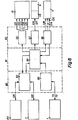
- FIG. 6 shows the individual components of the NC control 12, which are divided into input, central, output and peripheral units.
- the components as such are known, so that their operation is only described to the extent necessary for understanding the invention.
- the input unit 80 contains the operation interface 83 and the machine interface 84.
- the program input with memory 85 and the control panel 7 are connected to the operation interface 83 via the data bus 120.
- the data flow in the data bus 120 goes in both directions, which is indicated by the arrows.
- the complete program for the entire grinding process of the workpiece 9 is stored in the program input 85 (for example on magnetic memory), and / or the program can optionally be operated in the control panel 7 by the operator can be entered or changed.
- the operator stores the entered or changed data in one of the memories of the program input 85.
- the working cylinder 1 is connected to the machine interface 84 via the lines 72, 73 (FIGS. 4, 6, 7).
- the data belonging to the program are shown in FIGS. 7, 8.
- the two interfaces 83, 84 transfer the data to the central processing unit 90, in which they are processed taking into account the specified technology rules and are given as results in the output unit 82.
- the arrows of the connecting lines indicate the data flow, and in the output unit 82 there are as many interfaces 86, 87, 88 as there are peripheral actuating units 13, 11, 14, 56 necessary to control the entire grinding process of the workpiece 9.
- the hydraulic system 13 is connected via lines 121, 122, 123, 124, 125 to interface 86 for controlling valves 54, 55, 60 and controller 75 (FIG. 4).
- the hydraulic and flushing interface 87 is connected via lines 126, 127 to the feed pump 56 of the hydraulic system 13 and to the feed pump of the flushing and filter unit 14.
- the drive motor which drives the eccentric drives 11 in the planetary movement (FIGS. 1, 2) via the drives 20, 21, is controlled by the machine interface 88 via the line 128.
- the adjusting motor which adjusts the eccentricity of the eccentric drives 11 (FIGS. 1, 2) via the adjusting drives 37, 45, is controlled by the machine interface 88 via the line 129.
- the same machine interface 88 of FIG. 6 controls the electromagnet of the lifting cylinder 34 via the line 130, the clutch 31 in the driver 32 a short time before the eccentricity is adjusted coupled in and decoupled again after the set eccentricity (FIG. 2).
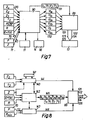
- FIG. 7 shows the input data which are necessary for carrying out the entire grinding process on the workpiece 9 and which are either stored in the program input 85 or are entered by the operator via the control panel 7.
- the limits of the entire movement of the tool 5 in the Z coordinate are determined.
- the values Zu for the upper limit and Z d for the lower limit (depth gauge 2) are entered.
- the value Z 2 indicates the path in mm that the tool 5 is to travel in the Z coordinate during a cycle within a cycle.
- the value t 2 indicates the time in seconds that must not be exceeded for grinding at the predetermined speed V 2 (see also FIG. 5).
- the amount P min is the lower limit in Kp / mm 2 , which the contact pressure between tool 5 and workpiece 9 should not fall below.
- this amount P min is intended as the lower limit for the planetary idling movements of the workpiece 9, which are carried out at the end of the entire grinding process without feed in the Z coordinate to increase the accuracy of the image of the workpiece 9 until the value P min is reached .
- the amount P max is the upper limit, which the pressure between tool 5 and workpiece 9 must not exceed, since otherwise their surfaces can be damaged.
- the amount R is used to enter the number of cycles or interval movements (FIG. 5; lifting V 3 , delivering V 1 ) for the entire grinding process.
- E f (Z) is used to enter the eccentricity as a function of the depth of penetration of the tool 5 and the workpiece 9 (Z coordinate).
- the amount of eccentricity E can be determined with which the planetary movement of the workpiece 9 is carried out in the X and Y coordinates should. Every amount of the penetration depth Z has a certain value of the eccentricity E.
- This dependence between Z and E can be represented in a graph as any curve. This dependency can preferably be represented as a straight line or as a circular arc.
- the technological values mentioned so far are transported via data bus 120 to central processing unit 90 and processed there.
- the measuring device 70 which has its sensor on or in the grinding gap 46 or in the feed line 171 of the rinsing liquid from the rinsing unit 14 to the rinsing channels in the workpiece 9, gives the electrical signals at any moment which indicate the actual pressure P between the tool 5 and the workpiece 9 specify, via line 73 to the central processing unit 90.
- the measuring device 71 the sensor z. B. is provided on the depth gauge 2 ( Figure 1), gives its information about the IST position of the tool 5 in the Z coordinate as electrical pulses by means of line 72 in the central processing unit 90th
- the feed pump in the flushing and filter unit 14 can also be controlled via line 127, so that the pressure of the flushing medium is adjusted within certain limits to the conditions in the grinding gap 46 between tool 5 and workpiece 9. This applies to the actual grinding process in the Z, coordinate and especially to the interval lifting and infeed movement (V 3 , V 1 ).
- the central processing unit 90 outputs the speeds V "V 2 , V 3 , which are adapted to the conditions in the grinding gap 46, and the dynamically controlled transitions V 1a ... V 3b into the advance selector 89 via the data bus 131. From there the individual information in a specific sequence via lines 121, 122, 123, 124, 125 to valves 54, 55, 60 and to controller 75 of hydraulic system 13.
- FIG. 8 shows the control of the hydraulic system 13 for each cycle.
- the two comparators 140, 143 and the processor 142 are components of the central processing unit 90 in FIGS. 6 and 7.
- the program input 85 or 7 is carried out approximately with the same values as in FIG. Z 2 and t 2 are the grinding path and the grinding time which the tool 5 may require in each cycle. These values are given in the comparator 140, which works with a clock 141 as a standard measure.
- the grinding path Z for all cycles serves as a basis for comparison and is fed into the comparator 140 and into the processor 142.
- the processor is connected to the comparator and monitors that the grinding process is ended in each cycle if the grinding path Z 2 has been reached before the grinding time t2 or vice versa.
- a termination signal is generated which reaches the advance selector 89 via the line 144.
- the values of Z 2 and t z can be different for each cycle. This depends on the type of spatial shape to be produced and on the material of the workpiece 9.
- the workpiece can, for example, be composed of several different materials.
- the processor 142 is entered the number R of the intended cycles. Furthermore, the processor receives the input of the eccentricity E as a function of the total grinding path Z. This has already been described in FIG. 7.
- the eccentric drives 11 are controlled in the same way as in the case of Embodiment of Figure 7. In each cycle, the eccentricity E of the planetary movement of the workpiece 9 can be different.
- the amount P m is the lower pressure limit in the grinding gap 46, which must not be undercut.
- the measuring device 70 supplies the actual value of the pressure between the tool 5 and the workpiece 9 to the comparator 143 via line 72, which compares it with P min .
- the processor 142 is in permanent communication with the comparator and, by changing the control signals on the data bus 145, ensures that the lower pressure limit P min is not reached. Should this nevertheless happen, a signal "No feed” is sent via line 146 to the Advance Selector 89. The program of the current cycle is run through again. In most cases, the conditions in the grinding gap have improved so that the machining of the workpiece 9 can continue.
- the central processing unit 90 in FIGS. 6 and 7 reacts in such a way that these movements are continued without feed up to the lower pressure limit P min and then switched off.
- the processor 142 of FIG. 8 outputs the manipulated variables for the speeds V1, V 2 , V 3 , the transitions V 1a ... V 3b and for the times t " (t" t 2 , t 3 %) via data bus 145 on the advance selector 89, which controls the valves 54, 55, 60 and the controller 75 in the hydraulic system 13 in a certain sequence via the lines 121, 122, 123, 124, 125.
- the contact pressure between the tool 5 and the workpiece 9 and the speeds of the various movements are adapted to the conditions in the grinding gap 46.
- FIGS. 1-9 Preferred exemplary embodiments of the invention have been described in FIGS. 1-9. These exemplary embodiments can be modified in individual parts, the actual inventive idea not being changed.
- the hydraulic system 13 of Figures 1 and 4 which performs the feed movement at low speed during grinding, the intermittent feed and lift movement at high speed and the transitions between the movements, are replaced by an electrical circuit.
- FIG. 1 shows only one pair of tools 5 and workpiece 9. Of course, several such pairs can be provided, all of which are machined in one operation. It should be noted that each pair (tool 5 and workpiece 9) is clamped on the plate 4 and table 10 offset from the other pair. These measures prevent inaccuracies in machining, which arise due to the elasticity of the machine parts 1, 3, 4, 8, 10 influenced by the dynamic machining forces. This problem arises not only when one side of the workpiece 9 is ground more than the other side, but also when machining is the same on all sides.
Landscapes
- Engineering & Computer Science (AREA)
- Mechanical Engineering (AREA)
- Chemical & Material Sciences (AREA)
- Chemical Kinetics & Catalysis (AREA)
- Electrochemistry (AREA)
- Grinding And Polishing Of Tertiary Curved Surfaces And Surfaces With Complex Shapes (AREA)
- Electrical Discharge Machining, Electrochemical Machining, And Combined Machining (AREA)
Description
Die Erfindung bezieht sich auf eine Maschine zur Herstellung eines Werkstückes nach dem Oberbegriff des Patentanspruchs 1.The invention relates to a machine for producing a workpiece according to the preamble of patent claim 1.
Bekanntlich umfaßt der Formenbau die Herstellung von Formen für den Druckguß, Spritzguß, das Stanzen, Warmpressen, Kaltpressen und Schmieden von Materialien aus Stahl, Metallen, Kunststoff, Gummi sowie deren Legierungen bzw. Mischungen. Diese Formen sind häufig kompliziert und weisen eine dreidimensionale Konstruktion auf. Besonders in der Flugzeug- und Automobilindustrie werden solch schwierig herstellbare Formen unter Einhaltung kleinster Toleranzen verlangt. Auf dieselbe Art und Weise werden Werkstücke oder Konstruktionsteile (z. B. im Triebwerkbau) aus schwer zerspanbaren Materialien (z.B. hoch warmfeste Legierungen) hergestellt. Bekanntlich werden solche Formen oder Triebwerkteile durch funkenerosive bzw. elektrochemische Maschinen hergestellt. Die hierfür benützten Elektroden haben die gleiche komplizierte Oberfläche wie die herzustellenden Formen bzw. Teile. Im Laufe der jüngsten Entwicklung werden solche Elektroden auf besonderen Maschinen hergestellt. Die Herstellung erfolgt in der Weise, daß die Elektrode aus dem vollen Material durch einen Schleifvorgang oder Feilvorgang herausgearbeitet wird. Das Material kann z. B. Graphit sein. Das hierfür erforderliche Werkzeug hat bereits die Form der Elektrode mit einem Untermaß. Durch eine Relativbewegung zwischen dem Werkzeuge und der aus dem vollen Stück herauszuarbeitenden Elektrode erfolgt der Schleifvorgang oder Feilvorgang. Zur Unterstützung des Schleif- oder Feilvorgangs wird ein Schleifmittel in die Oberfläche des Werkzeugs eingebracht. Ferner wird eine Flüssigkeit in den Spalt 46 zwischen Werkzeug und Werkstück getan. Die Relativbewegung setzt sich aus zwei Bewegungstypen zusammen. Der eine Typ ist die Vorschubbewegung des Schleif-oder Feilwerkzeugs zum oder vom Elektrodenwerkstück (senkrecht). Diese Vorschubbewegung kann auch kreisförmig (senkrecht) sein. Der andere Typ ist eine kreisende Bewegung des Elektrodenwerkstücks in der horizontalen Ebene. Die kreisende Bewegung wird auch als orbitale oder planetäre Bewegung bezeichnet. Sie kann auch kugelförmig sein.As is known, mold construction includes the production of molds for die casting, injection molding, stamping, hot pressing, cold pressing and forging materials made of steel, metals, plastic, rubber and their alloys or mixtures. These shapes are often complex and have a three-dimensional construction. In the aircraft and automotive industries in particular, molds that are difficult to manufacture with the smallest tolerances are required. Workpieces or structural parts (e.g. in engine construction) are made from materials that are difficult to machine (e.g. high-temperature alloys) in the same way. It is known that such shapes or engine parts are produced by spark erosion or electrochemical machines. The electrodes used for this have the same complicated surface as the molds or parts to be produced. In the course of recent development, such electrodes are manufactured on special machines. The production takes place in such a way that the electrode is worked out of the full material by a grinding or filing process. The material can e.g. B. be graphite. The tool required for this already has the shape of the electrode with an undersize. The grinding or filing process takes place through a relative movement between the tool and the electrode to be worked out from the full piece. To support the grinding or filing process, an abrasive is introduced into the surface of the tool. Furthermore, a liquid is placed in the
Der Radius bzw. die Exzentrizität der kreisenden Bewegung kann verstellt werden. Der Schleifvorgang wird solange durchgeführt bis das Elektrodenwerkstück die Raumform des Werkzeuges angenommen hat. Dann wird die relative Bewegung beendet. Dies erfolgt durch ein an der Maschine eingestelltes Maß, das auch Tiefenendmaß genannt wird. Die Raumform des Elektrodenwerkstückes kann gegenüber der Raumform des Werkzeugs verkleinert oder vergrößert werden. Dies wird durch Einstellen der gewünschten Exzentrizität der kreisenden Bewegung bewerkstelligt.The radius or the eccentricity of the circular movement can be adjusted. The grinding process is carried out until the electrode workpiece has assumed the spatial shape of the tool. Then the relative movement is ended. This is done using a dimension set on the machine, which is also known as the depth gauge. The three-dimensional shape of the electrode workpiece can be reduced or enlarged compared to the three-dimensional shape of the tool. This is accomplished by setting the desired eccentricity of the circular motion.
Wenn auch die DE-OS 2 603 614 eine Funkenerosionsmaschine, d.h. eine andere Gattung als die Formenschleifmaschine der Erfindung betrifft, wird in der Vorveröffentlichung eine kreisende Bewegung zwischen der aus Kupfer oder Messing bestehenden Elektrode und dem von der Elektrode elektroerosiv zu bearbeitenden Werkstück aus gehärtetem Stahl erzeugt. Zwischen Elektrode und Werkstück muß immer ein Arbeitsspalt mit einer dielektrischen Flüssigkeit eingehalten werden, in welchem die elektrischen Bearbeitungsfunken sich entladen können. Die kreisende Bewegung setzt sich aus zwei Hin- und Her-Bewegungen zusammen, die um 90° zueinander versetzt sind. Für jede Hin- und Her-Bewegung ist eine durch einen Motor angetriebene Kurvenscheibe vorgesehen, deren Umfang von einem Abtaster mechanisch abgetastet wird. Eine Änderung der Bewegungsamplitude ist nur dann möglich, wenn die Kurvenscheibe eine besondere Form seiner Umfangsfläche hat. Die Bewegungsamplitude kann nur während des Betriebes geändert werden. Ein wesentlicher Nachteil einer solchen Bewegungserzeugung liegt in der ungewollten Änderung der Amplituden der Bewegungen, die im Laufe einer längeren Betriebszeit durch Veränderung des Abtastdruckes und durch Verschleiß bzw. Verformung der Abtastflächen entstehen. Diese Änderungen können bei jeder Kurvenscheibe unterschiedlich sein, sodaß jede Hin-und Her-Bewegung eine andere Amplitude hat, wodurch die aus zwei Hin- und Her-Bewegungen zusammengesetzte Umlaufbewegung nicht mehr kreisförmig ist. Hierdurch berühren sich Elektrode und Werkstück, erzeugen einen Kurzschluß und beenden die funkenerosive Bearbeitung. Elektrode und Werkstück können an den Berührungsstellen deformiert oder sogar gänzlich unbrauchbar werden. Ein weiterer Nachteil liegt in der komplizierten mechanischen Übertragung zwischen Einstellung und Ausführung der Amplitudenänderung, welche Ungenauigkeiten erzeugt.Even if DE-OS 2 603 614 is a spark erosion machine, i.e. relates to a genus other than the mold grinding machine of the invention, in the prior publication, a circular movement between the electrode made of copper or brass and the workpiece to be machined by the electrode made of hardened steel is generated. A working gap with a dielectric liquid must always be maintained between the electrode and the workpiece, in which the electrical machining sparks can discharge. The circular movement consists of two back and forth movements, which are offset by 90 ° to each other. A cam driven by a motor is provided for each back and forth movement, the circumference of which is mechanically scanned by a scanner. A change in the movement amplitude is only possible if the cam has a special shape of its circumferential surface. The movement amplitude can only be changed during operation. A major disadvantage of such a movement generation is the unwanted change in the amplitudes of the movements which arise in the course of a longer operating time due to a change in the scanning pressure and through wear or deformation of the scanning surfaces. These changes can be different for each cam disc, so that each back and forth movement has a different amplitude, as a result of which the orbital movement composed of two back and forth movements is no longer circular. As a result, the electrode and workpiece touch, create a short circuit and end the electrical discharge machining. The electrode and workpiece can be deformed at the contact points or even become completely unusable. Another disadvantage is the complicated mechanical transmission between setting and executing the amplitude change, which produces inaccuracies.
Im US-Patent 4 277 915 ist eine Formenschleifmaschine mit mindestens zwei Exzenterantrieben für die kreisende Bewegung des Werkstückes relativ zum Werkzeug beschrieben. Der gewünschte Betrag der Exzentrizität für jeden Exzenterantrieb kann nur bei stillstehender Maschine, nach Lösen mehrerer Verbindungsschrauben und nach Anbringung einer Exzentrizität-Einstelleinrichtung geändert werden. Nachteilig ist hierbei, daß der eingestellte Betrag der Exzentrizität bei jedem Exzenterantrieb sich ungewollt verändern kann, wenn an jedem Exzenterantrieb die Verbindungsschrauben wieder angezogen werden. Exzenter- antriebe mit ungleichen Beträgen der Exzentrizität üben deformierende oder zerstörende Kräfte auf Maschinentisch, Werkstück und auf sich selber aus, wenn sie in Drehbewegungen versetzt werden.US Pat. No. 4,277,915 describes a form grinding machine with at least two eccentric drives for the circular movement of the workpiece relative to the tool. The desired amount of eccentricity for each eccentric drive can only be changed when the machine is at a standstill, after loosening several connecting screws and after attaching an eccentricity adjustment device. The disadvantage here is that the set amount of eccentricity can change unintentionally with each eccentric drive if the connecting screws are tightened again on each eccentric drive. Eccentric drives with unequal amounts of eccentricity exert deforming or destructive forces on the machine table, workpiece and on themselves when they are set into rotary movements.
Die bekannte Herstellungsweise durch Formenschleif-Maschinen hat also folgende Nachteile:
- - Die Exzentrizität der relativen Bewegung kann nicht während des Schleifvorgangs geändert werden. Zu diesem Zweck muß die Maschine stillgesetzt werden.
- - Der Anpreßdruck, mit dem das Werkzeug während des Schleifens an das Elektrodenwerkstück angepreßt wird, muß den sich ändernden Schleifzuständen angepaßt werden. Die Schleifzustände ändern sich je nach der Größe, der in Eingriff stehenden Schleiffläche des Werkzeugs und des Werkstücks. Besonders bei komplizierten dreidimensionalen Raumformen ändert sich die Größe der in Eingriff stehenden Schleifflächen oder deren Winkel innerhalb kurzer Zeit. Eine solche Anpassung des Anpreßdrucks an die Schleifverhältnisse und an die Bruchfestigkeit des Werkzeugs und des Werkstücks ist bei der bekannten Herstellungsweise nicht möglich. Daher besteht die Gefahr, daß der Anpreßdruck zu gewissen Zeiten entweder zu hoch oder zu niedrig ist. Dies bedeutet entweder mangelhafte Flächenteile oder Beschädigungen am Werkstück bzw. Werkzeug oder eine zu lange Schleifzeit. In beiden Fällen werden die Herstellungskosten unnötig erhöht.
- - Zur besseren Spülung des Schleifspaltes wird das Werkzeug in Intervallen vom Werkstück zurückgezogen und nach einer kurzen Zeit wieder zum Werkstück vorgeschoben. Die Spülflüssigkeit transportiert das abgetragene Material aus dem Spalt. Die Geschwindigkeit für das kurzzeitige Zurückziehen und Vorfahren ist größer als die Vorschubgeschwindigkeit während des Schleifens bzw. Feilens. Wenn das Werkzeug immer tiefer in das Werkstück eindringt, wird die Fläche, die am Schleifen bzw. Feilen beteiligt ist, größer. Die Flächenform wird komplizierter. In diesen Fällen ist die Geschwindigkeit für das schnelle Zurückziehen und Vorfahren nicht mehr auf den Zustand im Spalt angepaßt. Dies kann dann zu Beschädigungen der Fläche des Werkzeuges und Werkstückes führen.
- - Das Zurückziehen und Vorfahren des Werkzeuges erfolgt mit teilweise zu großer Kraft, weil die Kraft nicht auf das Gewicht des Werkzeugs abgestimmt werden kann. Bekanntlich wechselt das Gewicht von Werkzeug zu Werkzeug. Bei jedem Wechsel der Bewegungsrichtung und bei jedem Beschleunigen und Abbremsen der Bewegung ergeben sich Stöße auf das Werkzeug, welche seine präzise Einstellung zum Werkstück in nicht gewünschter Weise verändern. Das bedeutet eine schlechte Raumform des Werkstücks.
- - The eccentricity of the relative movement cannot be changed during the grinding process. The machine must be shut down for this purpose.
- - The contact pressure with which the tool is pressed against the electrode workpiece during grinding must be adapted to the changing grinding conditions. The grinding conditions change depending on the size, the engaged grinding surface of the tool and the workpiece. Particularly in the case of complicated three-dimensional spatial shapes, the size of the grinding surfaces engaged or their angles change within a short time. Such an adaptation of the contact pressure to the grinding conditions and to the breaking strength of the tool and the workpiece is not possible with the known production method. There is therefore a risk that the contact pressure is either too high or too low at certain times. This means either defective surface parts or damage to the workpiece or tool or an excessively long grinding time. In both cases, the manufacturing costs are unnecessarily increased.
- - For better flushing of the grinding gap, the tool is withdrawn from the workpiece at intervals and pushed back to the workpiece after a short time. The rinsing liquid transports the removed material out of the gap. The speed for brief retraction and advancement is greater than the feed speed during grinding or filing. As the tool penetrates deeper and deeper into the workpiece, the area involved in grinding or filing increases. The surface shape becomes more complicated. In these cases, the speed for rapid retraction and advancement is no longer adapted to the condition in the gap. This can lead to damage to the surface of the tool and workpiece.
- - The retraction and advancement of the tool takes place with excessive force, because the force cannot be matched to the weight of the tool. As is well known, the weight changes from tool to tool. Every time the direction of movement changes and every time the movement is accelerated and braked, the tool is impacted, which changes its precise setting in relation to the workpiece in an undesired manner. This means a poor spatial shape of the workpiece.
Die Erfindung hat die Aufgabe, die Nachteile der bekannten Maschinen zur Herstellung von Elektroden zu beseitigen. Durch eine besondere Vorrichtung kann die Exzentrizität während des Bearbeitens verstellt werden. Die Raumform des fertig bearbeiteten Elektrodenwerkstückes ist in jeder Weise komplementär zur Raumform des Werkzeugs. Mit einem einzigen Werkzeug können mehrere Werkstücke mit komplizerter Raumform hergestellt werden.The object of the invention is to eliminate the disadvantages of the known machines for producing electrodes. The eccentricity can be adjusted during machining by a special device. The spatial shape of the finished electrode workpiece is complementary to the spatial shape of the tool in every way. With a single tool, several workpieces with a complicated spatial shape can be produced.
Eine Baugruppe bewerkstelligt in jedem Zeitpunkt des Schleifens folgende Funktionen:
- - Anpassung der Anpreßkraft zwischen dem Werkzeug und dem Werkstück an die Zustände im Arbeitsspalt. Hierdurch werden Beschädigungen an Werkzeug und Werkstück sowie mangelhafte Herstellung von Flächen am Werkstück vermieden. Außerdem wird die Schleifzeit verkürzt. Die Herstellungskosten werden für das Werkstück gesenkt.
- -Anpassung der intervallmäßigen Abhebe- und Zustellgeschwindigkeit an die Zustände im Spalt und auch an die Menge der zugeführten Spülflüssigkeit. Hierdurch werden die Spülverhältnisse im Spalt verbessert. Das abgeschliffene Material wird sogar bei komplizierten Flächen vollständig aus dem Spalt entfernt.
- - Die Übergänge von der normalen Vorschubgeschwindigkeit zur wesentlich größeren intervallmäßigen Abhebe- und Zustellgeschwindigkeit und umgekehrt werden sanft gestaltet. Mit anderen Worten ausgedrückt werden der Beschleunigungs- und der Bremsvorgang dynamisch gesteuert. Hierdurch werden die sogenannten Schaltstö- ße oder Schläge und die damit verbundenen Geräusche vermieden. Die Maschine wird dadurch geschont, was ihre Lebensdauer ohne Einbuße an Präzision stark verlängert.
- - Adaptation of the contact pressure between the tool and the workpiece to the conditions in the working gap. This prevents damage to the tool and workpiece, as well as inadequate production of surfaces on the workpiece. The grinding time is also shortened. The manufacturing costs for the workpiece are reduced.
- Adaptation of the interval lifting and delivery speed to the conditions in the gap and also to the amount of the rinsing liquid supplied. This improves the rinsing conditions in the gap. The sanded material is completely removed from the gap, even on complicated surfaces.
- - The transitions from the normal feed speed to the much higher interval lifting and delivery speed and vice versa are designed gently. In other words, the acceleration and braking processes are controlled dynamically. This avoids the so-called switching impacts or shocks and the associated noise. This protects the machine, which greatly extends its service life without sacrificing precision.
Zur Lösung dieser Aufgabestellung wird die im Patentanspruch 1 definierte Erfindung vorgeschlagen.To solve this task, the invention defined in claim 1 is proposed.
Ein Ausführungsbeispiel der Erfindung wird anhand der Zeichnungen näher erläutert. Es zeigen:
- Figur 1: eine Maschine gemäß der Erfindung;
- Figur 2: die Vorrichtung für die planetäre Bewegung;
- Figur 3: ein Teil der Vorrichtung der Figur 2;
- Figur 4: die hydraulische Anlage für die Vorschub-, Rückzug- und Intervall-Bewegung;
- Figur 5: ein Diagramm der Vorschub- und Intervall-Bewegung;
- Figuren 6-8: die elektronische Steuerung für die in den Figuren 1, 2, 3 und 4 gezeigten Ausführungen der Erfindung.
- Figur 9: ein Detail der Maschine.
- Figure 1: a machine according to the invention;
- Figure 2: the device for the planetary movement;
- Figure 3: part of the device of Figure 2;
- Figure 4: the hydraulic system for the feed, retraction and interval movement;
- Figure 5: a diagram of the feed and interval movement;
- Figures 6-8: the electronic control for the embodiments of the invention shown in Figures 1, 2, 3 and 4.
- Figure 9: a detail of the machine.
Die Figur 1 zeigt den Hydraulikzylinder 1, in dem der Stößel bzw. die Pinole 3 bewegbar angeordnet ist. Am Stößel 3 ist die Stößelplatte 4 befestigt, die mittels der vier Säulen 8 und den Führungen 6 geführt wird. Von den Säulen sind nur zwei dargestellt. An der Stößelplatte 4 befindet sich eine Konstruktion, an der die Meßeinheit 2 befestigt ist. Diese Meßeinheit kann zum Beispiel der Tiefenendschalter sein, der den Arbeitsprozeß nach Erreichen der eingestellten Tiefe abstellt. An der unteren Seite der Stößelplatte 4 ist das dreidimensionale Formschleifwerkzeug 5 befestigt. Das Formschleifwerkzeug hat die Raumform, die das Werkstück 9 nach der Bearbeitung haben soll. Das Werkstück oder die Werkstück-Elektrode 9 besteht im vorliegenden Beispiel aus dem Material Graphit und ist in Blockform auf dem Arbeitstisch 10 befestigt. Die Werkstück-Elektrode 9 kann auch aus einem anderen Material, wie z.B. Metalle oder deren Legierungen oder aus isolierendem Material wie z.B. Holz bestehen. Das isolierende Material muß mit einer elektrisch leitenden Schicht versehen werden. Wesentlich ist die elektrische Leitfähigkeit des Materials, wenn die fertige Elektrode 9 für die elektroerosive bzw. elektrochemische Bearbeitung verwendet werden soll. Der Arbeitstisch 10 ist mit zwei Exzenterantrieben 11 verbunden, die den Arbeitstisch und das Werkstück 9 in die planetäre bzw. orbitale oder kreisende Bewegung bringen. Die Bewegung findet in den X- und Y-Koordinaten statt. Der Exzenterantrieb wird später im Zusammenhang mit den Figuren 2 und 3 näher beschrieben. Das Bedienpult 7 enthält eine größere Anzahl von Bedienungsorganen. Die Bedienungsperson kann mit diesen Organen die elektronische NC-Steuerung 12, die Hydraulikanlage 13, das Spül- und Filter-Aggregat 14 und die Antriebsmotoren, die im Maschinenuntergestell 15 angeordnet sind, betätigen oder ausschalten. Es sei darauf hingewiesen, daß die Bedienungsperson nur in ganz seltenen Fällen in den Ablauf des Arbeitsprozesses eingreift. Normalerweise erfolgt die Bearbeitung vollautomatisch, was später noch näher beschrieben wird. Der Arbeitsprozeß beginnt damit, daß die elektronische NC-Steuerung 12 über die Hydraulikanlage 13 die Stößelplatte 4 mit dem Formschleifwerkzeug 5 in Richtung Werkstück 9 absenkt. Gleichzeitig werden die beiden Exzenter-Antriebe 11 von der NC-Steuerung 12 in Betrieb gesetzt. Sie treiben den Arbeitstisch 10 und das Werkstück 9 in eine kreisende Bewegung. Der Betrag der Exzentrizität wird von der NC-Steuerung bestimmt. Dies wird später näher erläutert. Das Werkstück erhält durch diese Bewegung zum Formschleifwerkzeug 5 die gewünschte Raumform. Im Laufe der Bearbeitung bewegt sich das Werkzeug 5 mit einer bestimmten Vorschubgeschwindigkeit immer mehr in das Werkstück 9 hinein. Ein Schleifmittel sorgt für den richtigen Schleifvorgang. Das Schleifmittel kann in der Fläche des Werkzeugs 5 eingearbeitet sein oder im Spalt zwischen Werkstück und Werkzeug angeordnet sein.FIG. 1 shows the hydraulic cylinder 1 in which the tappet or the sleeve 3 is movably arranged. The tappet plate 4 is fastened to the tappet 3 and is guided by means of the four
Das Schleifmittel kann auch mit der Spülflüssigkeit in den Spalt transportiert werden. Die Spülflüssigkeit wird während des gesamten Arbeitsprozesses im Aggregat 14 aufbereitet und über Schläuche an den Arbeitstisch 10 transportiert. Das Werkstück 9, das vor dem Schleifprozeß mit mindestens einem, aber vorzugsweise mit einer Vielzahl von Spülkanälen versehen wurde, ist so am Arbeitstisch 10 befestigt, daß die vom Filter-und Spül-Aggregat 14 gelieferte Spülflüssigkeit in den Spalt gelangt. Wahlweise können Werkzeug 5 und/oder Werkstück 9 mit Spülkanälen versehen werden.The abrasive can also be transported into the gap with the rinsing liquid. The rinsing liquid is prepared in the
In der Figur 1 ist die Raumform des Werkzeugs 5 sehr einfach dargestellt. Dies soll nur nur allgemeinen Illustration dienen. In Wirklichkeit sind die Flächen bzw. ist die Raumform wesentlich komplizierter.In Figure 1, the spatial shape of the tool 5 is shown very simply. This is for general illustration only. In reality, the surfaces or the spatial form are much more complicated.
Während des Schleifvorganges besteht die Notwendigkeit, daß das Material, das abgeschliffen worden ist, entfernt werden muß, da es den Schleifvorgang nur behindert. Zur Entfernung dieses Materials wird in bestimmten zeitlichen Abschnitten bzw. Intervallen die Stößelplatte 4 mit dem Werkzeug 5 abgehoben. Die Spülflüssigkeit entfernt nun das abgeschliffene Material. Nach kurzer Zeit bewegt sich die Stößelplatte 4 mit dem Werkzeug 5 in Richtung Werkstück 9 und bearbeitet es mit der normalen Vorschubgeschwindigkeit weiter. Da die Abhebe- und Zustell-Bewegung eine viel größere Geschwindigkeit hat als die normale Vorschub-Bewegung, werden besondere Vorkehrungen getroffen, daß der Beschleunigungsvorgang und der Abbremsvorgang nicht abrupt stattfinden sondern dynamisch gesteuert werden. Dies wird später im Zusammenhang mit der Figur 5 näher erklärt. Ferner muß dafür Sorge getragen werden, daß die Geschwindigkeit der Abhebe- und Zustell-Bewegung des Werkzeugs 5 so gewählt wird, daß das abgeschliffene Material vorzugsweise vollkommen entfernt wird. Dabei darf aber keine Beschädigung am Werkstück 9 entstehen, das im vorliegenden Ausführungsbeispiel aus dem Material Graphit besteht. Im Folgenden sei diese Problematik an zwei Beispielen kurz erläutert. Zuerst sei angenommen, daß das Formschleifwerkzeug 5 noch nicht tief in das Werkstück eingedrungen sei. Die Abhebe-Bewegung bewirkt, daß das abgeschliffene Material zusammen mit der Spülflüssigkeit aufgewirbelt und entfernt wird. Das Werkzeug 5 wird anschließend mit der hohen Zustell-Geschwindigkeit zum Werkstück 9 bewegt. Wenn die Fläche vom Werkzeug und Werkstück sehr nahe sind, baut sich plötzlich ein hoher Druck der Spülflüssigkeit auf, der irgendwelche Reste von abgeschliffenem Material entfernt. Als zweites Beispiel sei angenommen, daß das Werkzeug 5 schon sehr tief in das Werkstück 9 eingedrungen ist. Bei der Intervall-Abhebe-Bewegung muß nun Sorge getragen werden, daß die Geschwindigkeit so ist, damit die komplizierten Flächen nicht beschädigt werden und dennoch das abgeschliffene Material entfernt wird. In der Praxis ist dies mit der Abhebebewegung allein nicht möglich. Daher wird die anschließende Zustellbewegung des Werkzeugs 5 in Richtung Werkstück 9 dazu benutzt, den restlichen Teil des abgeschliffenen Materials vollkommen zu entfernen. Dies kann z.B. dadurch bewerkstelligt werden, daß mit einer erhöhten Geschwindigkeit zugestellt wird. Der Druck baut sich sehr schnell in der Spülflüssigkeit auf. Im Gegensatz hierzu kann auch mit einer geringeren Geschwindigkeit zugestellt werden. Dann baut sich der Druck nicht so schnell in der Spülflüssigkeit auf. Die Wahl der Geschwindigkeit der Zustell-Bewegung des Werkzeugs 5 ist abhängig von der Kompliziertheit und Verletzlichkeit der dreidimensionalen Flächen. Dies wird durch die NC-Steuerung 12 bewerkstelligt.During the grinding process, there is a need to remove the material that has been ground down because it only hinders the grinding process. To remove this material, the plunger plate 4 is lifted off with the tool 5 at certain time intervals or intervals. The rinsing liquid now removes the ground material. After a short time, the ram plate 4 moves with the tool 5 in the direction of the
Während des gesamten Schleifvorganges kann die Notwendigkeit eintreten, daß die Exzentrizität der planetären Bewegung des Werkstücks 9 in den X- und Y-Koordinaten geändert werden muß. Dies erfolgt durch die in den Figuren 2 und 3 gezeigten Ausführungsbeispiele.During the entire grinding process, there may be a need to change the eccentricity of the planetary movement of the
Wenn gemäß Figur 1 das Formschleifwerkzeug 5 genügend tief in das Graphit-Werkstück 9 eingedrungen ist, so stellt das Tiefenendmaß 2, das mit einem Gegenkontakt in Berührung kommt, den gesamten Arbeitsprozeß ab.If, according to FIG. 1, the form grinding tool 5 has penetrated sufficiently deeply into the
Abschließend sei noch erwähnt, daß die Kraft, mit der das Werkzeug 5 gegen das Werkstück 9 gedrückt wird, den Verhältnissen im Schleifspalt 46 angepaßt wird. Bekanntlich ändern sich mit Fortschreiten des Schleifens die Verhältnisse im Spalt. Dies hängt damit zusammen, daß die Größe der in Eingriff stehenden Flächen sich ändert. Damit der gesamte Schleifprozeß innerhalb einer vernünftigen Zeit durchgeführt werden kann, muß die Anpreßkraft angepaßt werden. Dies geschieht auf zweierlei Weisen. Die NC-Steuerung 12 wird nach dem Tiefenmaß (Z-Achse) oder nach der Zeit bzw. Geschwindigkeit programmiert. In der Nähe des Arbeitstisches 10 ist ein Sensor installiert, der z.B. auf die Durchflußmenge der Spülflüssigkeit zwischen dem Spül- und Filter-Aggregat 14 und dem Arbeitstisch 10 anspricht. Dieser Sensor beeinflußt entsprechend den Änderungen der Durchflußmenge die NC-Steuerung 12. Der Sensor muß nicht immer vorhanden sein. Im Folgenden sei angenommen, daß nur das Programm auf Tiefenmaß oder Arbeitszeit die Anpassung der Anpreßkraft zwischen Werkzeug 5 und Werkstück 9 vornimmt. Die herzustellende Raumform ist bekannt. Daher weiß man auch die ungefähre Größe der in Eingriff stehenden Flächen in Abhängigkeit der Tiefe (Z-Achse) oder der Bearbeitungszeit bei einer bestimmten Bearbeitungsgeschwindigkeit. Entsprechend der voraus berechneten Änderung der in Eingriff stehenden Flächengröße kann die Anpreßkraft geändert werden. Wenn der Sensor noch zusätzlich oder allein benutzt wird, kann der NC-Steuerung 12 mitgeteilt werden, daß die vorgeschriebene Tiefe in der gewünschten Zeit oder die gewünschte Tiefe in der vorgegebenen Zeit nicht erreicht wurde. Die NC-Steuerung 12 kann in diesem Fall die Anpreßkraft erhöhen und den Schleifprozeß beschleunigen. Hierbei muß aber die Kompliziertheit und Verletzlichkeit der Fläche berücksichtigt werden. Daher empfiehlt es sich, einen oberen Grenzwert der Anpreßkraft festzulegen. Dies kann z. B. in der NC-Steuerung 12 für jede Größe der in Eingriff stehenden Flächen programmiert werden.Finally, it should be mentioned that the force with which the tool 5 is pressed against the
Die Figur 2 zeigt im Schnitt einen der beiden Exzenterantriebe 11. Es handelt sich hier um den linken Antrieb der Figur 1. Da beide Antriebe identisch sind wird im Folgenden nur dieser linke Antrieb erklärt. Der Antrieb besteht aus dem Gehäuse 16, in welchem über die Lager 17 eine Hülse 18 drehbar um ihre Achse 19 gelagert ist. Das Gehäuse 16 des Exzenterantriebs ist am Träger 49 befestigt. Am gleichen Träger ist auch der rechte Exzenterantrieb angebracht. Jeder Exzenterantrieb hat die gleiche Länge, die z.B. 30 cm beträgt. Die Hülse 18 wird durch einen nicht gezeichneten Elektromotor, der sich im Maschinenuntergestell 15 befindet, in Drehbewegung versetzt. Dies erfolgt über den Antriebsriemen 20 und Treibrad 21. Der Antriebsriemen 20 kann vorzugsweise ein Gummiriemen mit Innenzähnen oder eine Kette sein. Das Antriebsrad 21 hat entsprechende Vertiefungen oder Zähne. Die Geschwindigkeit des Antriebsmotors kann je nach den gewünschten Verhältnissen geändert werden. Dies stellt entweder die Bedienungsperson am Bedienpult 7 oder die NC-Steuerung 12 ein. In der Hülse 18 ist die Welle 22 drehbar gelagert. Die Figur 2 zeigt die Anordnung der Welle 22 außerhalb der Drehachse 19 der Hülse 18. Die Drehachse 23 der Welle 22 ist einige Millimeter nach links von der Drehachse 19 der Hülse 18 versetzt. Die Welle 22 ist an ihrem oberen Ende zu einem Flansch 24 ausgebildet. Der Flansch 24 steht mit der Hülse 18 über Verzahnung 25 in Verbindung. Diese Verzahnung ist in der Figur 3 detailliert dargestellt. Sie besteht aus dem oberen Zahnkranz 26, der am Flansch 24 befestigt ist, und aus dem unteren Zahnkranz 27, der an der Hülse 18 befestigt ist. Beide Zahnkränze greifen ineinander und können voneinander getrennt werden. Der Flansch 24 hat auf der dem Arbeitstisch 10 zugewandten Seite einen Kurbeltrieb 29. Wie Figur 2 zeigt ist der Kurbeltrieb nicht mittig in der Achse 23 seiner Welle 22 angeordnet. Der Kurbeltrieb 29 ist durch entsprechende relative Drehung der Welle 22 zur Hülse 18 so gezeichnet, daß die Exzentrizität gleich Null ist. Im Folgenden wird dies noch näher erklärt werden. Wenn nun der Haupt-Antriebsmotor den Antrieb 20, 21 in Drehbewegung versetzt, dreht sich die Hülse 18, die über die Verzahnung 25 die Welle 22 mitnimmt. Da der Kurbeltrieb 29 keine Exzentrizität hat, bewegt der Arbeitstisch 10 sich nicht in eine kreisende oder orbitale bzw. planetäre Bewegung. In diesem Zusammenhang sei darauf hingewiesen, daß der rechte Exzenterantrieb 11, identisch ist, vom gleichen Haupt-Antriebsmotor angetrieben wird und die gleiche Exzentrizität gleich Null hat. Der Antrieb erfolgt vorzugsweise über den gleichen Antriebsriemen 20.FIG. 2 shows an average of one of the two eccentric drives 11. This is the left drive of FIG. 1. Since both drives are identical, only this left drive is explained below. The drive consists of the
Im Folgenden wird die Einstellung einer gewünschten Exzentrizität beschrieben. Dies wird mit dem unteren Teil der Figur 2 bewerkstelligt. Die Kupplung 31 muß zu diesem Zweck in den Mitnehmer 32 eingekuppelt werden. Dieses Einkuppeln erfolgt in der Weise, daß der Hubzylinder 34, der in der Trägerkonstruktion 35 befestigt ist, seine Pinole 36 gegen den Anschlag des Verstellantriebsrad 37 drückt. Die Welle 38, die in Hülse 39 drehbar und verschiebbar angeordnet ist und das Rad 37 des Verstellantriebs mit der Kupplung 31 verbindet, wird durch die Pinole 36 nach oben verschoben, sodaß das Rad 37 mit dem Mitnehmer 32 eingekuppelt ist. Die Hülse 39 ist in einem Träger 33 befestigt. Der Träger 33 und die Trägerkonstruktion 35 sind genau wie der Träger 49 feste Bestandteile des Maschinenuntergestells 15. Der obere Teil des Mitnehmers 32 enthält eine Ausnehmung mit einem Innen-Zahnkranz 40. Der untere Teil der Welle 22 ist zu einem Flansch ausgebildet. Dieser Flansch trägt auf seiner Seitenwand einen Außen-Zahnkranz 41, der mit dem Innen-Zahnkranz 40 in Eingriff steht. Die Pinole 36 bewegt den fest eingekuppelten Mitnehmer 32 bis zum Anschlag 42 nach oben. Die Welle 22 wird gegen die Kraft der Feder 43 nach oben verschoben. Durch dieses Verschieben werden die Zahnkränze 26, 27 der Verzahnung 25 voneinander getrennt, sodaß zwischen der Hülse 18 und der Welle 22 keine starre Verbindung mehr besteht. Nun kann die gewünschte Exzentrizität eingestellt werden. Ein nicht gezeichneter Elektromotor z. B. Schrittmotor, der auch im Maschinenuntergestell 15 vorgesehen ist, treibt über den Riemen 45, der mit beiden Exzenterantrieben 11 verbunden ist, die Antriebsräder 37 an. Die Welle 22 dreht sich relativ zur Hülse 18, über die Zahnkränze 40, 41, Mitnehmer 32, Kupplung 31, Welle 38 und Antriebsrad 37. Der Verstellantrieb 37 und 45 ist nur solange im Betrieb bis die gewünschte Exzentrizität durch Drehung des Kurbelzapfens 29 am Arbeitstisch 10 eingestellt ist. Hierzu wird eine Zeit benötigt, die zwischen 1-5 Sekunden liegt. Anschließend fährt die Pinole 3 in ihre Ausgangsposition zurück. Der Verstellantrieb 37, 45 und die Kupplung 31 folgen dieser Bewegung. Die Welle 22 bewegt sich unter der Kraft der Feder 43 in ihre Anfangsposition und rastet über die Verzahnung 25 mit der Hülse 18 ein. Der beschriebene Vorgang der Verstellung der Exzentrizität der beiden Exzenterantriebe 11 wird entweder vom Bedienpult 7 durch die Bedienungsperson oder von der NC-Steuerung 12 durch ein Programm gesteuert. Der Betrag der eingestellten Exzentrizität wird durch einen Sensor 50 erfaßt, der am oberen Zahnkranz 26 der Verzahnung 25 angeordnet ist (Figur 3). An Stelle des Sensors 50 kann auch ein Schrittmotor verwendet werden, der als Antriebsmotor zum Einstellen der Exzentrizität benutzt wird. Dieser Betrag wird auf ein Anzeigegerät im Bedienpult 7 oder in die NC-Steuerung 12 gegeben. Der Hauptantrieb 20, 21 wird wieder gestartet. Der Arbeitstisch 10 führt nun die planetäre Bewegung mit der eingestellten Exzentrizität aus. Wenn die herzustellende Raumform am Werkstück 9 weitere Verstellungen der Exzentrizität verlangt, kann dies ohne weiteres so durchgeführt werden wie es beschrieben wurde.The setting of a desired eccentricity is described below. This is accomplished with the lower part of FIG. 2. The
Da bei der planetären Bewegung des Arbeitstisches 10 oft große Massen (Gewichte) bewegt werden, besteht die Forderung zu einem Massenausgleich. Dies kann dadurch bewerkstelligt werden, daß unter dem Arbeitstisch 10 mindestens ein dritter Exzenterantrieb angeordnet ist, dessen Kurbeltrieb 29 Gegengewichte in planetäre Bewegungen versetzt. Der dritte Exzenterantrieb ist mit den beiden beschriebenen Antrieben 11 identisch. Der Hauptantrieb 20, 21, der für die Drehbewegung der Hülse 18 verantwortlich ist, und der Verstellantrieb 37, 45, der für Einstellung der Exzentrizität verantwortlich ist, sind identisch. Der dritte Exzenterantrieb wird auch von den gleichen Motoren angetrieben. Der einzige Unterschied des dritten Exzenterantriebes besteht darin, daß der Hauptantrieb 20, 21 und der Verstellantrieb 37, 45 in umgekehrter Richtung bewegt werden. Dies kann dadurch bewerkstelligt werden, daß die Treibräder 21 und 37 in umgekehrter Weise an die Riemen bzw. Ketten 20, 45 angelegt werden. Wesentlich ist, daß der dritte Exzenterantrieb die Gegengewichte in umgekehrter Richtung zur planetären Bewegung des Arbeitstisches 10 bewegt. In einigen Fällen können die Gewichte bzw. Massen des Arbeitstisches 10 wesentlich größer sein als die Gegengewichte. Dann wird mit dem dritten Exzenterantrieb eine größere Exzentrizität für die kleineren Gegengewichte eingestellt als für den Arbeitstisch 10 mit den beiden Exzenterantrieben 11. Zum Beispiel stellt man mit dem dritten Exzenterantrieb ein um den Faktor 10 größeren Radius ein. Der dritte Exzenterantrieb wird selbstverständlich auch vom Bedienpult 7 oder von der NC-Steuerung 12 gesteuert.Since large masses (weights) are often moved during the planetary movement of the work table 10, there is a requirement for a mass balance. This can be accomplished in that at least one third eccentric drive is arranged under the work table 10, the crank drive 29 of which counterweights causes planetary movements. The third eccentric drive is identical to the two
Die Figur 3 zeigt die Verzahnung 25. Der obere Zahnkranz 26, der an der unteren Seite des Flansches 24 angebracht ist, und der untere Zahnkranz 27, der auf der Hülse 18 angebracht ist, sind normalerweise miteinander im Eingriff. Nur während der Verstellung der Exzentrizität sind die beiden Zahnkränze getrennt. Im vorliegenden Beispiel hat jeder Zahnkranz 180 Zähne. Dies bedeutet eine Winkelverdrehung von 2° pro Zahn. Dies entspricht einer durchschnittlichen Exzentrizitätsverstellung von 0,1 mm. Selbstverständlich können diese Werte durch entsprechende konstruktive Maßnahmen verkleinert oder vergrößert werden. Der obere Zahnkranz 26 trägt eine Scheibe 28 mit Strichmarken 29. Die Scheibe 28 kann auch am Außenrand des Flansches 24 befestigt sein. Bei der Verstellung der Exzentrizität macht diese Scheibe die Drehung des Flansches 24 mit. Ein Sensor 50 tastet die an ihm vorbeilaufenden Strichmarken 29 ab und gibt die entsprechenden elektrischen Signale über die Leitungen 51 auf das Anzeigegerät im Bedienpult 7 oder in die NC-Steuerung 12. Die Strichmarken 29 können optisch abgetastet werden. Dann besteht die Scheibe aus Glasmaterial mit schwarzen Strichen 29. Der Sensor 50 hat zwei Lichtschranken, die in einem bestimmten Abstand zueinander angeordnet sind. Hierdurch werden sowohl die Richtung als auch der Betrag der Exzenter-Verstellung detektiert. Die entsprechenden elektrischen Signale sind auf den Leitungen 51 entweder in analoger oder digitaler Form vorhanden. Bei magnetischer Abtastung der Marken 29 besteht die Scheibe 28 aus magnetisch nicht leitendem Material. Der Sensor 50 hat zwei magnetische Abtastvorrichtungen, die die Richtung und den Betrag der Exzenter-Verstellung als Signale auf den Leitungen 51 bekannt geben. Mit einem anderen Sensor kann die Abtastung auch mechanisch oder elektrisch erfolgen. Solche Sensoren sind bekannt, sodaß nicht näher darauf eingegangen wird.Figure 3 shows the
Abschließend wird erwähnt, daß die planetäre Bewegung nicht nur mit dem Beispiel der Figur 2 sondern auch mit einem Kreuztisch erzeugt werden kann. Bekanntlich muß der eine Tisch Sinus-Bewegungen und der andere Tisch Cosinus-Bewegungen ausführen. Die Überlagerung beider Bewegungen ergibt die planetäre Bewegung.Finally, it is mentioned that the planetary movement can be generated not only with the example of FIG. 2 but also with a cross table. As is well known, one table must perform sine movements and the other table must perform cosine movements. The superposition of both movements results in the planetary movement.
Die Figur 4 zeigt die hydraulische Anlage 13, mit der die Vorschub-Bewegung des Schleifwerkzeugs 5 und seine in bestimmten Zeiten stattfindende Abhebe- und Zustell-Bewegung bewerkstelligt werden. Das 4/3-Wegeventil 55 ist über Leitung 52 mit der Pumpe 56 verbunden, die das für die Hydraulikanlage benötigte Druckmedium, z. B. Öl, liefert und gemäß den Vorschubverhältnissen unterschiedliche Fördermengen liefern kann. Vorschubgeschwindigkeit und Fördermenge der Pumpe stehen je nach Vorwahl von 55 in einem festen Verhältnis. Die Rückflußleitung 53 des Ventils 55 ist mit dem Reservoir 57 verbunden, aus dem die Pumpe 56 ihr Öl bezieht. Das Ventil 55 enthält die beiden Elektromagnete 58, 59, die von der NC-Steuerung 12 über Leitungen 121, 125 betätigt werden. An beiden Enden des Ventils 55 ist ein Symbol für die Ventilfedern (Rückstellfedern) gezeichnet. Hinter dem 4/3-Wegeventil 55 liegt ein Proportionalventil 60, das nahe beim Arbeitszylinder 1 der Formschleifmaschine angeordnet ist. Auf kurze Verbindungsleitungen 63, 64 zum Arbeitszylinder 1 ist großer Wert gelegt.FIG. 4 shows the
Zur Erklärung der Wirkungsweise der Figur 4 sei nun angenommen, daß das Werkzeug 5, das bekanntlich an der Stößelplatte 4 der Pinole 3 befestigt ist, in Richtung Werkstück 9 und Arbeitstisch 10 bewegt werden soll. Es handelt sich um die Vorschubbewegung und die schnelle Zustell- bewegung. Für den Vorschub abwärts wird Magnet 58 am Ventil 55 angewählt; die Schnellzustellung wird ohne Vorwahl an Ventil 55 nur mit Signal 123 gesteuert und Freigabe 124 abgesichert. Die anderen Bewegungen werden später diskutiert. Für die Vorschubbewegung betägtigt die NC-Steuerung 12 den Elektromagneten 58, so daß das Ventil 55 die Leitung 52 von der Pumpe 56 mit der Leitung 61 zum Proportionalventil 60 und die Rückleitung 62 vom Proportionalventil mit der Druckleitung 61 verbindet. Die NC-Steuerung 12 beeinflußt über Leitung 123, Komparator 76, Verstärker 77, Schalter 78 des Proportionalreglers 75 den Elektromagneten 65 des Proportionalventils 60 so, daß die Druckleitungen 61, 64 miteinander verbunden sind. Das Druckmedium, z.B. ÖI, gelangt nun von der Förderpumpe 56 über die Druckleitungen 52, 61, 64 in den oberen Raum des Arbeitszylinders 1, so daß sich der Kolben 111 der Pinole 3 nach unten bewegt. Hierdurch fließt das Öl aus dem unteren Raum des Arbeitszylinders 1 über die Rückflußleitungen 63, 62. Die Kolbenfläche des unteren Raums ist wesentlich kleiner als die des oberen Raums. Dies geschieht aus dem Grund, damit die Förderpumpe 56 eine geringere Ölmenge fördern muß. Im Ventil 55 wird das rückfließende ÖI wieder in die Druckleitung 61 eingeführt. In der Rückflußleitung 63 befindet sich ein Sperrventil 67, das den Ölfluß aus dem unteren Raum des Arbeitszylinders 1 sperrt. Im vorliegenden Fall kann das Öl nur über die Drossel 66 fließen, die einen so hohen Druck aufbaut, daß der Stößel 3 und der Kolben 111 mit einer sehr kleinen Geschwindigkeit das Werkzeug 5 zum Werkstück 9 bewegt. Soll diese Geschwindigkeit vergrößert werden, so geschieht dies über Ventil 68, welches nach Überschreiten eines bestimmten Druckes öffnet und dadurch einen Bypass zur Drossel 66 bildet. Die Figur 4 zeigt in der Nähe des Werkzeugs 5 und Arbeitstisch 10 mit Werkstück 9 zwei Boxen 70, 71. Sie sollen symbolisch Meßgeräte darstellen. Das Meßgerät 70 soll ein Kraftmesser sein, der die Anpreßkraft F zwischen dem Werkzeug 5 und dem Werkstück 9 mißt und ein Spannungssignal U (analog oder digital) über Leitung 73 in die NC-Steuerung 12 gibt. Das Meßgerät 71 soll ein Wegmesser sein, der den Weg Z mißt, den das Werkzeug 5 in der Z-Koordinate zurücklegt. Der Wegmesser 71 erzeugt elektrische Impulse, die über Leitung 72 in die NC-Steuerung 12 gegeben werden. Diese Impulse enthalten die Information über die Richtung der Bewegungen und die momentane Stellung des Werkzeugs. Der Weg Z kann z. B. durch das Meßgerät 1 der Figur 1 detektiert werden. Die beiden Meßgeräte 70, 71 haben ihre Sensoren an den für sie günstigsten Orten angeordnet.To explain the mode of operation of FIG. 4, it is now assumed that the tool 5, which is known to be attached to the plunger plate 4 of the sleeve 3, should be moved in the direction of the
Der in der Figur 4 dargestellte Proportionalregler 75 enthält einen Komparator 76, der die SOLLwert-Signale für Vorschubgeschwindigkeit (NC-Steuerung 12, Leitung 123) mit den ISTwert-Signalen des Meßorgans 69 vergleicht. Das Meßorgan 69 detektiert die wirkliche Stellung des Steuerschiebers im Proportionalventil 60. Bei einer Differenz zwischen den beiden elektrischen Signalen erzeugt der Komparator 76 ein elektrisches Differenzsignal, das über den Verstärker 77 mit einstellbarem Verstärkungsgrad, Schalter 78 zum Elektromagneten 65 gegeben wird und den Steuerschieber im Proportionalventil 60 solange bewegt bis die gewünschte Ventilstellung, die in der NC-Steuerung 12 programmiert ist, eingestellt ist. Der Proportional regler 75 macht den Steuerschieber des Ventils 60 unempfindlich gegen statische und dynamische Störkräfte, so daß die Bewegung zwischen Werkzeug 5 und Werkstück 9 sehr genau nach den in der NC-Steuerung 12 programmierten Werten gesteuert wird. Die NC-Steuerung 12 verarbeitet auch die ISTwert-Signale der Meßgeräte 70, 71. Die Anpassung erfolgt in jedem Augenblick der Vorschubbewegung, der intervallmäßigen Zustell-Rückzugbewegung und während der dynamisch gesteuerten Übergänge zwischen den einzelnen Bewegungstypen. Ferner erfolgt die Anpassung, wenn während des Schleifvorganges die in Eingriff stehenden Flächen zwischen Werkzeug 5 und Werkstück 9 größer werden. Die Anpassungsvorgänge werden später im Zusammenhang mit den Figuren 6, 7, 8 näher beschrieben. Der Proportional regler 75 ist nur dann in Betrieb, wenn ein sogenanntes «Freigabe» (enable) Signal zusätzlich auf der Leitung 124 vorhanden ist. Durch diese Maßnahme wird sichergestellt, daß der Kolben 111 keine ungewollten Bewegungen im Arbeitszylinder 1 macht. Wenn kein . Freigabesignal vorhanden ist, befindet sich der Schalter 78 in der gezeichneten Ruhestellung. Der Proportionalregler 75 ist nun nicht in Betrieb. Der Steuerschieber des Proportionalventils 60 wird durch die Rückstellfeder, deren Symbol oberhalb des Ventils in der Figur 4 gezeichnet ist, zurückgestellt, sodaß der Kolben 111 keine Bewegungen ausführen kann.The
Die Figur 4 zeigt zwischen der Druckleitung 52 der Pumpe 56 und der Rückflußleitung 53 zum Reservoir 57 ein zweites Proportionalventil 54, das über Leitung 122 von der NC-Steuerung 12 elektrisch angesteuert wird. Mit diesem Proportionalventil kann der Maximaldruck für die gesamte Hydraulikanlage geändert werden. Druckerniedrigung erfolgt durch Vermindern der Federvorspannung 54, so daß ein Teil des Öls aus der Druckleitung 52 in die Rückflußleitung 53 fließt. Ein höherer Druck der Pumpe 56 wird erreicht durch Erhöhen der Federvorspannung über den Magnet am Ventil 54. Die NC-Steuerung 12 bestimmt über Leitung 122 den Betrag der Druckänderung. Die NC-Steuerung 12 wird über den Datenbus 120 mit dem Programm über die Schleifarbeit einschließlich den verschiedenen Bewegungstypen zwischen Werkzeug 5 und Werkstück 9 versorgt. Wenn z.B. innerhalb einer vorgegebenen Zeit t2 der vorgegebene Schleifweg Z2 (Fig. 5) nicht erreicht wurde, wird der Druck in bestimmter Weise erhöht, sodaß der Schleifprozeß beschleunigt wird. Die Beschleunigung wird jedoch unter Berücksichtigung der Verletzlichkeit der Materialien von Werkzeug 5 und Werkstück 9 eingestellt. Der Druck wird durch das Proportionalventil 54 erniedrigt, wenn das Werkzeug 5 den vorgegebenen Schleifweg Z2 schneller als in der vorbestimmten Zeit t2 zurückgelegt hat.FIG. 4 shows a second
Wenn nun im Programm, das der NC-Steuerung 12 über den Datenbus 120 eingegeben worden ist, eine Entfernung des Werkzeugs 5 vom Werkstück 9 vorgesehen ist, so wird das 4/3-Wegeventil 55 über Leitung 125 angesteuert. Der Elektromagnet 59 bewegt den Steuerschieber im Ventil 55 so, daß die Druckleitung 52 der Förderpumpe 56 mit der Leitung 62 verbunden wird. Die Leitung 61 wird mit der Rückleitung 53 verbunden, die zum Reservoir 57 führt. Ferner werden über Leitung 123 der Proportionalregler 75 und das Proportionalventil 60 angesteuert. Der Elektromagnet 65 bewegt den Steuerschieber im Ventil 60 so, daß die Förderpumpe 56 über Druckleitungen 52, 62, 63, Ventil 67, das in der Durchflußrichtung kein Sperrventil ist, ÖI in den unteren Raum des Zylinders 1 pumpt. Aus dem oberen Raum des Zylinders 1 gelangt das Öl über Leitungen 64, 61, 53 in das Reservoir 57. Das Werkzeug 5 bewegt sich nun mit kleiner Geschwindigkeit vom Werkstück 9 fort.If a distance of the tool 5 from the
Anhand der Figur 4 wurden bisher die Bewegungen des Werkzeugs 5 besprochen, die mit geringer Geschwindigkeit vom oder zum Werkstück 9 durchgeführt werden.The movements of the tool 5, which are carried out at or at a low speed from or to the
Nun müssen auch intervallmäßige Bewegungen mit sehr viel höherer Geschwindigkeit durchgeführt werden, die in bestimmten Zeiten, z.B. zwischen 1 Sekunde und 120 Sekungen liegen können. Diese intervallmäßigen Bewegungen bestehen aus einem schnellen Abheben des Werkzeugs 5 vom Werkstück 9 und einem schnellen Zustellen des Werkzeugs 5 zum Werkstück 9. An dieser Stelle sei darauf hingewiesen, daß die schnelle Abhebe- und Zustell-Bewegung nicht plötzlich auftreten darf, da sonst Flächenteile des Werkstücks 9 beschädigt werden können. Dieser Nachteil der bekannten Anlagen ist dadurch zu erklären, daß z.B. bei einer schnellen Abhebebewegung des Werkzeugs 5 vom Werkstück 9 ein Vakuum im Spalt gebildet wird, da die Spülflüssigkeit aus dem Spülaggregat 14 nicht schnell genug nachfließen kann. Ein solches Vakuum führt dazu, daß der Kolben 111 und Stößel 3 im Arbeitszylinder 1 mit großer Kraft nach oben bewegt werden müssen, was Beschädigungen an den Flächen hervorruft. Außerdem erzeugen solche plötzlichen Änderungen der Bewegungsabläufe dynamische Störungen wie z. B. starke Schläge und Stöße im gesamten System. Dies kann die hohe Präzision der einjustierten Konstruktionsteile verschlechtern. Das Gleiche gilt auch, wenn das Werkzeug 5 mit großer Geschwindigkeit zum Werkstück 9 bewegt wird und plötzlich stehen bleibt. Hier baut sich plötzlich ein hoher Druck auf, da die Spülflüssigkeit in dem sich verengenden Spalt sehr schnell komprimiert wird und das Spül- aggregat 14 nicht in der Lage ist, Gegenmaßnahmen einzuleiten wie z. B. schnelleres Absaugen und Verringerung der Menge der Spülflüssigkeit. Auch in diesem Fall ergeben sich starke Schläge und Stöße im System.Now interval movements must also be carried out at a much higher speed, which in certain times, e.g. can be between 1 second and 120 seconds. These interval movements consist of a quick lifting of the tool 5 from the
Da die intervallmäßigen Bewegungen zum Entfernen des abgeschliffenen Materials aus dem Schleifspalt46 unumgänglich notwendig sind, vermeidet die Erfindung die genannten Nachteile der unerwünschten Schläge und Stöße. Schläge und Stöße werden durch das Ausführungsbeispiel der Figur 4 vermieden. Die nachteiligen, plötzlichen Druckänderungen der Spülflüssigkeit werden durch ein Ausgleichgefäß 170 eliminiert, das gemäß Figur 9 in der Flüssigkeitsleitung 171 zwischen dem Spülaggregat 14 und dem Werkzeug 5 bzw. Werkstück 9 angeordnet ist. Die Spülflüssigkeit steht in der Leitung 171 unter Druck, der durch die Förderpumpe im Spülaggregat 14 erzeugt wird. Das Ausgleichgefäß 170 ist in der Mitte durch eine elastische Membrane 172 in die beiden Räume 173, 174 unterteilt. Der obere Raum 173 enthält Luft und ist abgedichtet. In den unteren Raum 174 gelangt die Spülflüssigkeit. Bei plötzlicher Druckerhöhung im Schleifspalt 46, die durch schnelles Bewegen des Werkzeuges 5 zum Werkstück 9 entsteht, weicht die Spülflüssigkeit in den unteren Raum 174 des Ausgleichgefäßes 170 aus. Hierdurch wird die plötzliche Druckerhöhung im Schleifspalt 46 vermieden. Bildet sich im Schleifspalt 46 eine Druckverminderung aus (Werkzeug 5 bewegt sich vom Werkstück 9 fort), so fließt genügend Spülflüssigkeit aus dem unter Druck stehenden Raum 174 in den Schleifspalt 46 und zwar zusätzlich zu der von der Pumpe im Aggregat 14 geförderten Spülflüssigkeit. Der Luftdruck im oberen Raum 173 unterstützt diesen Vorgang. Hierdurch wird in diesem Fall eine schädliche Druckverminderung im Schleifspalt46 vermieden, und die Spülung läuft in kürzerer Zeit und mit größerer Menge an Spülflüssigkeit ab, sodaß die Pumpe und die Leitungen im gesamten Spülkreis kleiner dimensioniert werden können. Das Ausgleichgefäß 170 der Figur 9 funktioniert auch ohne die Membrane 172.Since the interval movements are inevitable for removing the ground material from the grinding
Beim Ausführungsbeispiel der Figur 4 der Erfindung startet die NC-Steuerung 12 diese schnellen Intervall-Bewegungen über die Leitungen 121, 122, 123, 125. Die Ventile 54, 55, 60 steuern diese schnellen Bewegungen. Das Proportionalventil 60 ist so konstruiert, daß in Zusammenarbeit mit der NC-Steuerung 12 die Übergänge zwischen den intervallmäßigen Bewegungen (große Geschwindigkeit) und den Vorschub- und Rückzugsbewegungen (kleine Geschwindigkeit) sanft gestaltet werden. Die Hydraulikanlage ist also in der Lage, die sehr großen Unterschiede der Geschwindigkeitsänderungen auf ein vernünftiges Maß zu reduzieren. Hierdurch wird die Arbeitsgenauigkeit der Maschine erhöht.In the exemplary embodiment in FIG. 4 of the invention, the
Anhand der Figur 5 soll nun der Bewegungsablauf des Werkzeuges 5 unter Berücksichtigung der erfindungsgemäßen hydraulischen Anlage der Figur 4 näher erklärt werden. Auf der Abszisse der Figur 5 sind die Zeit t und auf der Ordinate der Weg Z aufgetragen. Es sei nun angenommen, daß das Werkzeug 5 mit großer Geschwindigkeit V1 in Richtung Werkstück 9 bewegt wird. Der Weg, den das Werkzeug 5 bis zum Werkstück 9 zurücklegt, ist mit Z, bezeichnet. Der erste Teil V1a der Geschwindigkeit ist der gesteuerte Übergang (Beschleunigen) von der Geschwindigkeit «Null» zur großen Zustellgeschwindigkeit V,. Wenn das Werkzeug 5 kurz vor dem Werkstück 9 sich befindet, erfolgt der gesteuerte Übergang (Bremsen) von der großen Zustellgeschwindigkeit V, zur Geschwindigkeit «Null». Dieser Teil ist mit Vlb bezeichnet. Nach einer kurzen Zeit t1 von ca. 0,1 Sekunde (Geschwindigkeit = 0) fährt das Werkzeug 5 mit der kleinen Vorschubgeschwindigkeit V2. In dieser Zeit t2 von ca. 1-30 Sekunden wird das Werkstück 9 geschliffen. Das Werkstück 9 führt die planetäre Bewegung aus. Die planetären Antriebe 11 der Figuren 1 und 2 setzen den Arbeitstisch 10 in Bewegung. Das Werkzeug 5 dringt hierbei um den Weg Z2 in das Werkstück 9 ein. Auch bei der kleinen Vorschubgeschwindigkeit V2 sind die gesteuerten Übergänge V2a (Beschleunigen) und V21 (Bremsen) vorgesehen. Nach einer kurzen Zeit t3 von ca. 0,4 Sekunden wird das Werkzeug 5 mit der großen Geschwindigkeit V3 vom Werkstück 9 abgehoben. Der hierbei zurückgelegte Weg Z3 ist gleich lang wie der Zustellweg Z1' aber um den Schleifweg Z2 nach unten verschoben. Die Übergänge V3a (Beschleunigen) und V3b (Bremsen) sind auch hier vorhanden. Das Werkzeug 5 bleibt für eine kurze Zeit t4 von ca. 0,5 Sekunden in der vom Werkstück 9 entferntesten Position (Geschwindigkeit = 0). Dann beginnt der nächste Zyklus. Der in der Figur 5 gezeigte Zyklus dauert eine Zeit, die zwischen 1 bis 60 Sekunden liegt. Die Anlage der Figur 4sorgt dafür, daß die Geschwindigkeiten V1, V2, V3 und ihre Übergänge V1a, V1b' V2a, V2b' V3a, V3b den augenblicklichen Zuständen im Schleifspalt angepaßt werden. Dies gilt besonders für den Fall, wenn das Werkzeug 5 sich immer tiefer in das Werkstück 9 einarbeitet, und die in Eingriff stehenden Flächen größer werden. Die Geschwindigkeiten und ihre Übergänge werden geändert. Die Zeiten t1, t2, t3, t4 können z. B. so geändert werden, daß die Ruhezeiten entfallen und die Schleifzeit t2 verlängert wird. Die Schleifzeit t2 kann auch verkürzt werden. Die Dauer eines Zyklusses kann auch länger als 60 Sekunden gemacht werden. So folgt ein Zyklus dem anderen so lange, bis die Schleifarbeit beendet ist. Wie später im Zusammenhang mit den Figuren 6, 7, 8 noch näher erläutert wird, können die bei Erreichen der vorgeschriebenen Bearbeitungstiefe im Werkstück 9 (d. h. zum Zeitpunkt der Beendigung der Schleifarbeit) ein oder mehrere Zyklen V3, V, ohne Vorschubbewegung V2 wiederholt werden. Die Anzahl dieser sogenannten «Nachschleif»-Zyklen kann entweder fest programmiert oder abhängig von einem minimalen Wert des Anpeßdruckes im Schleifspalt gemacht werden. Dies wird durch die NC-Steuerung 12 bewerkstelligt. Der Vorteil dieser Zyklen liegt darin, daß die Genauigkeit der geschliffenen räumlichen Abmessungen des Werkstücks 9 nach allen Seiten erhöht wird.The movement sequence of the tool 5 will now be explained in more detail with reference to FIG. 5, taking into account the hydraulic system according to the invention from FIG. The time t is plotted on the abscissa of FIG. 5 and the path Z on the ordinate. It is now assumed that the tool 5 is moved towards the
Die Figur 6 zeigt die einzelnen Bauteile der NC-Steuerung 12, die in Input-, Zentral-, Output-und Peripherieeinheiten eingeteilt sind. Die Bauteile als solche sind bekannt, so daß deren Funktionsweise nur soweit beschrieben wird, wie es für das Verständnis der Erfindung notwendig ist. Die Input-Einheit 80 enthält den Operation-Interface 83 und den Maschinen-Interface 84. Die Programmeingabe mit Speicher 85 und das Bedienpult 7 sind über den Datenbus 120 mit dem Operation-Interface 83 verbunden. Der Datenfluß im Datenbus 120 geht in beide Richtungen, was durch die Pfeile angedeutet ist. Wie bereits im Zusammenhang mit den Figuren 1 und 4 gesagt, ist das vollständige Programm für den gesamten Schleifprozeß des Werkstücks 9 in der Programmeingabe 85 eingespeichert (z. B. auf Magnetspeicher), und/oder das Programm kann wahlweise im Bedienpult 7 durch die Bedienungsperson eingegeben oder geändert werden. Die Bedienungsperson speichert die eingegebenen oder geänderten Daten in einem der Speicher der Programmeingabe 85. Der Arbeitszylinder 1 ist mit dem Maschinen-Interface 84 über die Leitungen 72, 73 verbunden (Figuren 4, 6, 7). Die zum Programm gehörenden Daten gehen aus den Figuren 7, 8 hervor. Die beiden Interfaces 83, 84 geben die Daten in die zentrale Recheneinheit 90, in der sie unter Berücksichtigung der vorgegebenen Technologieregeln verarbeitet werden und als Ergebnisse in die Output-Einheit 82 gegeben werden. Die Pfeile der Verbindungsleitungen deuten den Datenfluß an, und in der Output-Einheit 82 sind soviele Interfaces 86, 87, 88 vorgesehen, wie periphere Stelleinheiten 13, 11, 14, 56 notwendig sind zur Steuerung des gesamten Schleifprozesses des Werkstückes 9. Die Hydraulikanlage 13 steht über die Leitungen 121, 122, 123, 124, 125 mit dem Interface 86 für die Steuerung der Ventile 54, 55, 60 und des Reglers 75 (Figur 4) in Verbindung. Das Hydraulik- und Spül-Interface 87 ist über Leitungen 126, 127 mit der Förderpumpe 56 der Hydraulikanlage 13 und mit der Förderpumpe des Spül- und Filteraggregates 14 verbunden. Der Antriebsmotor, der über die Antriebe 20, 21 die Exzenterantriebe 11 in die planetäre Bewegung (Figuren 1, 2) antreibt, wird vom Maschinen-Interface 88 über die Leitung 128 angesteuert. Der Verstellmotor, der über die Verstellantriebe 37, 45, die Exzentrizität der Exzenterantriebe 11 (Figuren 1, 2) verstellt, wird vom Maschinen-Interface 88 über die Leitung 129 angesteuert. Das gleiche Maschinen-Interface 88 der Figur 6 steuert über die Leitung 130 den Elektromagneten des Hubzylinders 34 an, der kurze Zeit vor der Verstellung der Exzentrizität die Kupplung 31 in den Mitnehmer 32 einkoppelt und nach eingestellter Exzentrizität wieder entkoppelt (Figur 2).FIG. 6 shows the individual components of the
Die Figur 7 zeigt die Eingangsdaten, die für die Durchführung des gesamten Schleifprozesses am Werkstück 9 notwendig sind und in der Programmeingabe 85 entweder eingespeichert sind oder über das Bedienpult 7 durch die Bedienungsperson eingegeben werden. Die Grenzen der gesamten Bewegung des Werkzeugs 5 in der Z-Koordinate werden festgelegt. Die Werte Zu für die obere Grenze und Zd für die untere Grenze (TiefenEndmaß 2) werden eingegeben. Mit dem Wert Z2 wird der Weg in mm angegeben, den das Werkzeug 5 während des Schleifens innerhalb eines Zyklusses in der Z-Koordinate zurücklegen soll. Der Wert t2 gibt die Zeit in Sekunden an, die für das Schleifen mit der vorgegebenen Geschwindigkeit V2 nicht überschritten werden darf (siehe auch Figur 5). Der Betrag Pmin ist der untere Grenzwert in Kp/mm2, den der Anpreßdruck zwischen Werkzeug 5 und Werkstück 9 nicht unterschreiten sollte. Ferner ist dieser Betrag Pmin als untere Grenze für die planetären Leerlaufbewegungen des Werkstücks 9 gedacht, welche am Ende des gesamten Schleifprozesses ohne Vorschub in Z-Koordinate zur Erhöhung der Genauigkeit des Abbildes des Werkstück 9 solange vorgenommen werden, bis der Wert Pmin erreicht ist. Der Betrag Pmax ist der obere Grenzwert, den der Druck zwischen Werkzeug 5 und Werkstück 9 nicht überschreiten darf, da sonst ihre Flächen verletzt werden können. Mit dem Betrag R wird die Anzahl der Zyklen bzw. der Intervall-Bewegungen (Figur 5; Abheben V3, Zustellen V1) für den gesamten Schleifprozeß eingegeben. Mit E = f(Z) wird die Exzentrizität als Funktion der Eindringtiefe des Werkzeugs 5 und des Werkstücks 9 (Z-Koordinate) eingegeben. Da man bei jeder Eindringtiefe Z weiß, wie viele Flächen des Werkzeugs 5 und des Werkstücks 9 miteinander in Eingriff stehen, läßt sich der Betrag der Exzentrizität E feststellen, mit dem die planetäre Bewegung des Werkstücks 9 in den X- und Y-Koordinaten durchgeführt werden soll. Zu jedem Betrag der Eindringtiefe Z gehört ein bestimmter Wert der Exzentrizität E. Diese Abhängigkeit zwischen Z und E kann in einem Graph als beliebige Kurve dargestellt werden. Vorzugsweise ist diese Abhängigkeit als eine Gerade oder als ein Kreisbogen darstellbar. Die bisher genannten technologischen Werte werden über den Datenbus 120 in die zentrale Recheneinheit 90 transportiert und dort verarbeitet. Das Meßgerät 70, das seinen Sensor am oder im Schleifspalt 46 oder in der Zuleitung 171 der Spülflüssigkeit vom Spülaggregat 14 zu den Spülkanälen im Werkstück 9 hat, gibt in jedem Augenblick die elektrischen Signale, die den IST-Druck P zwischen Werkzeug 5 und Werkstück 9 angeben, über die Leitung 73 zur zentralen Recheneinheit 90. Das Meßgerät 71, dessen Sensor z. B. am Tiefenmaß 2 (Figur 1) vorgesehen ist, gibt seine Information über die ISTPosition des Werkzeugs 5 in der Z-Koordinate als elektrische Impulse mittels Leitung 72 in die zentrale Recheneinheit 90.FIG. 7 shows the input data which are necessary for carrying out the entire grinding process on the
In dieser Recheneinheit der Figur 6 werden sämtliche Eingangsdaten nach vorgegebenen Regeln verarbeitet. Dies wird im folgenden anhand der Figuren 1, 2, 5, 6, 7 erläutert. Der Antriebsmotor, der Verstellmotor und der Hubzylinder 34 der Exzenterantriebe 11 werden über die Leitungen 128, 129, 130 angesteuert. Die Förderpumpe 56 wird über Leitung 126 angesteuert und erzeugt in der Hydraulikanlage 13 (Figur 4) den Druck in der Weise, daß die Anpreßkraft stets an die Verhältnisse im Schleifspalt 46 zwischen Werkzeug 5 und Werkstück 9 angepaßt ist. Diese Anpassung erfolgt während des Schleifprozesses (Vorschubbewegung des Werkzeugs 5 in Z2-Koordinate und planetäre Bewegung des Werkstücks 9 in X-, Y-Koordinaten). Die Förderpumpe im Spül- und Filteraggregat 14 kann ebenfalls über Leitung 127 angesteuert werden, so daß der Druck des Spülmediums in gewissen Grenzen den Verhältnissen im Schleifspalt 46 zwischen Werkzeug 5 und Werkstück 9 angepaßt wird. Dies gilt für den eigentlichen Schleifprozeß in der Z,-Koordinate und besonders für die Intervall-Abhebe- und Zustellbewegung (V3, V1).In this arithmetic unit of Figure 6, all input data are processed according to predetermined rules. This is explained below with reference to FIGS. 1, 2, 5, 6, 7. The drive motor, the adjustment motor and the lifting
Die zentrale Recheneinheit 90 gibt über den Datenbus 131 die Geschwindigkeiten V" V2, V3, die an die Verhältnisse im Schleifspalt 46 angepaßt sind, und die dynamisch gesteuerten Übergänge V1a... V3b in den Advance Selektor 89. Von dort gelangen die einzelnen Informationen in einer bestimmten Sequenz über die Leitungen 121, 122, 123, 124, 125 auf die Ventile 54, 55, 60 und auf den Regler 75 der Hydraulikanlage 13.The
Die Figur 8 zeigt die Steuerung der Hydraulikanlage 13 für jeden Zyklus. Die beiden Komparatoren 140, 143 und der Prozessor 142 sind Bestandteile der zentralen Recheneinheit 90 der Figuren 6 und 7. Die Programmeingabe 85 oder 7 wird ungefähr mit den gleichen Werten wie in Figur 7 durchgeführt. Z2 und t2 sind der Schleifweg und die Schleifzeit, welche das Werkzeug 5 in jedem Zyklus benötigen darf. Diese Werte werden in den Komparator 140 gegeben, der mit einer Uhr 141 als Standardmaß zusammenarbeitet. Der Schleifweg Z für alle Zyklen dient als Vergleichsbasis und wird in den Komparator 140 und in den Prozessor 142 gegeben. Der Prozessor steht in Verbindung mit dem Komparator und überwacht, daß in jedem Zyklus der Schleifvorgang beendet wird, wenn der Schleifweg Z2 vor der Schleifzeit t2 oder umgekehrt erreicht wurde. In diesem Fall wird ein Beendigungssignal erzeugt, das über die Leitung 144 auf den Advance Selektor 89 gelangt. Die Werte von Z2 und tz können für jeden Zyklus unterschiedlich sein. Dies richtet sich nach der Art der herzustellenden Raumform und nach dem Material des Werkstücks 9. Das Werkstück kann z.B. aus mehreren, unterschiedlichen Materialien zusammengesetzt sein. Zu diesem Zweck wird dem Prozessor 142 die Anzahl R der vorgesehenen Zyklen eingegeben. Ferner erhält der Prozessor die Eingabe der Exzentrizität E als Funktion des gesamten Schleifwegs Z. Dies ist bei der Figur 7 bereits beschrieben worden. Die Steuerung der Exzenter- antriebe 11 erfolgt in gleicher Weise wie beim Ausführungsbeispiel der Figur 7. In jedem Zyklus kann die Exzentrizität E der planetären Bewegung des Werkstücks 9 anders sein. Der Betrag Pm ist die untere Druckgrenze im Schleifspalt 46, die nicht unterschritten werden darf. Das Meßgerät 70 liefert über Leitung 72 den IST-Wert des Druckes zwischen Werkzeug 5 und Werkstück 9 an den Komparator 143, der ihn mit Pmin vergleicht. Der Prozessor 142 steht mit dem Komparator in dauernder Verbindung und sorgt durch Veränderung der Stellsignale auf dem Datenbus 145, daß die untere Druckgrenze Pmin nicht erreicht wird. Sollte dies dennoch geschehen, wird ein Signal «Kein Vorschub» über Leitung 146 in den Advance Selektor 89 gegeben. Das Programm des augenblicklichen Zyklusses wird noch einmal durchgefahren. In den meisten Fällen haben sich die Verhältnisse im Schleifspalt gebessert, so daß die Bearbeitung des Werkstücks 9 fortgesetzt werden kann. Wenn jedoch am Ende des gesamten Schleifprozesses die sogenannten «Leerlauf»-Planetärbewegungen programmiert sind, dann reagiert die zentrale Recheneinheit 90 der Figuren 6 und 7 in der Weise, daß diese Bewegungen ohne Vorschub bis zur unteren Druckgrenze Pmin fortgesetzt und dann abgeschaltet werden.FIG. 8 shows the control of the
Der Prozessor 142 der Figur 8 gibt die Stellgrößen für die Geschwindigkeiten V1, V2, V3, die Übergänge V1a... V3b und für die Zeiten t" (t" t2, t3 ... ) über Datenbus 145 auf den Advance Selektor 89, der in bestimmter Sequenz die Ventile 54, 55, 60 und den Regler 75 in der Hydraulikanlage 13 über die Leitungen 121, 122, 123, 124, 125 steuert. Hierbei werden genau wie bei der Figur 7 die Anpreßkraft zwischen dem Werkzeug 5 und dem Werkstück 9 und die Geschwindigkeiten der verschiedenen Bewegungen an die Verhältnisse im Schleifspalt 46 angepaßt.The
Bevorzugte Ausführungsbeispiele der Erfindung sind in den Figuren 1-9 beschrieben worden. Diese Ausführungsbeispiele können in einzelnen Teilen abgewandelt werden, wobei der eigentliche Erfindungsgedanke nicht geändert wird. So kann z.B. die hydraulische Anlage 13 der Figuren 1 und 4, welche die Vorschubbewegung mit kleiner Geschwindigkeit während des Schleifens, die intervallmäßigen Zustell- und Abhebebewegung mit hoher Geschwindigkeit und die Übergänge zwischen den Bewegungen durchführt, ersetzt werden durch eine elektrische Schaltung.Preferred exemplary embodiments of the invention have been described in FIGS. 1-9. These exemplary embodiments can be modified in individual parts, the actual inventive idea not being changed. For example, the
Ferner zeigt die Figur 1 nur ein Paar Werkzeug 5 und Werkstück 9. Selbstverständlich können mehrere solcher Paare vorgesehen werden, die alle in einem Arbeitsgang bearbeitet werden. Hierbei ist zu beachten, daß jedes Paar (Werkzeug 5 und Werkstück 9) zum anderen Paar versetzt an der Platte 4 und Tisch 10 aufgespannt wird. Durch diese Maßnahmen werden Ungenauigkeiten bei der Bearbeitung vermieden, die durch die Elastizität der von den dynamischen Bearbeitungskräften beeinflußten Maschinenteile 1, 3, 4, 8, 10 entstehen. Dieses Problem tritt nicht nur dann auf, wenn eine Seite des Werkstückes 9 stärker geschliffen wird als die andere Seite, sondern auch bei einem allseits gleichen Bearbeiten.Furthermore, FIG. 1 shows only one pair of tools 5 and
Claims (23)
Applications Claiming Priority (4)
| Application Number | Priority Date | Filing Date | Title |
|---|---|---|---|
| CH743282 | 1982-12-21 | ||
| CH7432/82 | 1982-12-21 | ||
| CH560883A CH663745A5 (en) | 1983-10-14 | 1983-10-14 | Machine tool makes electroerosion electrodes for aircraft |
| CH5608/83 | 1983-10-14 |
Publications (3)
| Publication Number | Publication Date |
|---|---|
| EP0118606A2 EP0118606A2 (en) | 1984-09-19 |
| EP0118606A3 EP0118606A3 (en) | 1985-12-27 |
| EP0118606B1 true EP0118606B1 (en) | 1989-04-12 |
Family
ID=25698072
Family Applications (1)
| Application Number | Title | Priority Date | Filing Date |
|---|---|---|---|
| EP83112067A Expired EP0118606B1 (en) | 1982-12-21 | 1983-12-01 | Machine for making an electrode of a definite shape by means of a structural-grinding tool |
Country Status (3)
| Country | Link |
|---|---|
| US (1) | US4557075A (en) |
| EP (1) | EP0118606B1 (en) |
| DE (1) | DE3379579D1 (en) |
Families Citing this family (9)
| Publication number | Priority date | Publication date | Assignee | Title |
|---|---|---|---|---|
| CH661890A5 (en) * | 1983-10-01 | 1987-08-31 | Werner Ullmann | DRIVE FOR A MACHINE FOR THE PRODUCTION OF A WORKPIECE OF A SPECIFIC ROOM MOLD BY MEANS OF A MOLD GRINDING TOOL. |
| US4768308A (en) * | 1986-12-17 | 1988-09-06 | University Of Rochester | Universal lens polishing tool, polishing apparatus and method of polishing |
| WO1990008626A1 (en) * | 1989-02-03 | 1990-08-09 | Extrude Hone Corporation | Method and abrading tools for orbital grinding |
| US5081794A (en) * | 1990-08-17 | 1992-01-21 | Haney Donald E | Sander with orbiting platen and abrasive |
| US5181342A (en) * | 1990-08-17 | 1993-01-26 | Haney Donald E | Sander with orbiting platen and abrasive |
| US20080197010A1 (en) * | 2007-02-21 | 2008-08-21 | Chih Lin | Apparatus and method for air relief in an air switch |
| JP5484551B1 (en) * | 2012-11-20 | 2014-05-07 | 株式会社キョクトー | Polishing method of electrode tip |
| CN113001366B (en) * | 2021-03-01 | 2023-05-09 | 天津派浦澜能源科技有限公司 | Rust removal device for conveying pipeline surface |
| CN115519442A (en) * | 2022-09-27 | 2022-12-27 | 青岛威特动力木业机械有限公司 | Grinding machine |
Family Cites Families (11)
| Publication number | Priority date | Publication date | Assignee | Title |
|---|---|---|---|---|
| US2921487A (en) * | 1956-08-27 | 1960-01-19 | Schabot Bernard William | Indexing fixture |
| US3443341A (en) * | 1963-08-30 | 1969-05-13 | Honda Motor Co Ltd | Gear grinding machine |
| US3698138A (en) * | 1969-08-13 | 1972-10-17 | Toyoda Machine Works Ltd | Grinding machine with adaptive control system |
| US4156327A (en) * | 1972-05-16 | 1979-05-29 | Easco-Sparcatron, Inc. | Method for total form machining of metal |
| GB1407726A (en) * | 1973-03-28 | 1975-09-24 | Grafton Corp | Apparatus for use in forming electrodes |
| US3988863A (en) * | 1973-09-14 | 1976-11-02 | Oconnor Thomas John | Structure for and method of total form abrasion machining |
| CA1037292A (en) * | 1975-02-04 | 1978-08-29 | Triangle Tool Company | Apparatus for obtaining relative orbital movement in electrical discharge machining |
| DE2711697C2 (en) * | 1977-03-17 | 1983-11-17 | Friedrich Deckel AG, 8000 München | Device for feed and retraction control of the electrode of an electrical discharge machine |
| US4186529A (en) * | 1977-06-28 | 1980-02-05 | S. E. Huffman Corporation | Programmably controlled method for grinding end cutting tools and the like |
| US4186527A (en) * | 1978-08-07 | 1980-02-05 | Hausermann Abrading Process Company | Apparatus for shaping electrodes |
| US4277915A (en) * | 1979-07-06 | 1981-07-14 | Hausermann Abrading & Process Co. | Apparatus for shaping electrodes |
-
1983
- 1983-12-01 DE DE8383112067T patent/DE3379579D1/en not_active Expired
- 1983-12-01 EP EP83112067A patent/EP0118606B1/en not_active Expired
- 1983-12-16 US US06/562,108 patent/US4557075A/en not_active Expired - Fee Related
Also Published As
| Publication number | Publication date |
|---|---|
| DE3379579D1 (en) | 1989-05-18 |
| EP0118606A3 (en) | 1985-12-27 |
| US4557075A (en) | 1985-12-10 |
| EP0118606A2 (en) | 1984-09-19 |
Similar Documents
| Publication | Publication Date | Title |
|---|---|---|
| DE102006015711B3 (en) | punch | |
| DE2824266C2 (en) | Copy device for deburring workpieces | |
| DE69421859T2 (en) | Grinding machine | |
| EP0118606B1 (en) | Machine for making an electrode of a definite shape by means of a structural-grinding tool | |
| AT516507A4 (en) | forging machine | |
| EP0045380A2 (en) | Control circuit for an adjusting and dressing device of a grinding wheel | |
| DE19536036C2 (en) | Step feed processing system | |
| CH658617A5 (en) | TOOTHED RIM GRINDING MACHINE WITH DOUBLE TAPERED GRINDING WHEEL. | |
| EP3501730A1 (en) | Dental mill and method | |
| DE3200979A1 (en) | ELECTRODE FEEDING SYSTEM FOR ELECTRICAL MACHINING | |
| DE2818667A1 (en) | MACHINE TOOL FOR SPATIAL POLISHING WITH MAGNETIC GRINDING POWDER IN THE MAGNETIC FIELD OF WORKPIECES IN THE SHAPE OF A ROTATING BODY | |
| CH663745A5 (en) | Machine tool makes electroerosion electrodes for aircraft | |
| EP3357636B1 (en) | Tool module for finishing | |
| DE9005834U1 (en) | MANIPULATOR FOR FORGING MACHINES, ESPECIALLY MULTI-STAINLESS FORGING MACHINES | |
| CH631913A5 (en) | DEVICE FOR CONTROLLING THE INPUT OF A GRINDING WHEEL RELATIVE TO A DRESSING DEVICE. | |
| DE10107484B4 (en) | Stroke position control of the ram of punch presses | |
| DE2645426C2 (en) | Device for the dimensionally controlled machining of workpieces on honing machines | |
| EP0165249B1 (en) | Drive for form-grinding a work-piece | |
| EP0292642B1 (en) | Method and device for controlling the generating mechanism of a gear-grinding machine | |
| DE2919829A1 (en) | Press mould copying polishing machine - has copying unit with control system for travel and pressure at polishing head | |
| DE3441305C2 (en) | ||
| DE19722229A1 (en) | Adjustment device for tools of a forging machine with different forming stages | |
| DE3703848A1 (en) | Device for advancing a honing tool | |
| DE2362173B2 (en) | PROBE FOR INTERMITTENT SCANNING | |
| DE4413229A1 (en) | Method and apparatus for the finish machining of gears |
Legal Events
| Date | Code | Title | Description |
|---|---|---|---|
| PUAI | Public reference made under article 153(3) epc to a published international application that has entered the european phase |
Free format text: ORIGINAL CODE: 0009012 |
|
| AK | Designated contracting states |
Designated state(s): DE FR GB IT |
|
| 17P | Request for examination filed |
Effective date: 19850116 |
|
| RAP1 | Party data changed (applicant data changed or rights of an application transferred) |
Owner name: ULLMANN, WERNER, DR. |
|
| PUAL | Search report despatched |
Free format text: ORIGINAL CODE: 0009013 |
|
| AK | Designated contracting states |
Designated state(s): DE FR GB IT |
|
| 17Q | First examination report despatched |
Effective date: 19860730 |
|
| GRAA | (expected) grant |
Free format text: ORIGINAL CODE: 0009210 |
|
| AK | Designated contracting states |
Kind code of ref document: B1 Designated state(s): DE FR GB IT |
|
| PG25 | Lapsed in a contracting state [announced via postgrant information from national office to epo] |
Ref country code: IT Free format text: LAPSE BECAUSE OF FAILURE TO SUBMIT A TRANSLATION OF THE DESCRIPTION OR TO PAY THE FEE WITHIN THE PRESCRIBED TIME-LIMIT;WARNING: LAPSES OF ITALIAN PATENTS WITH EFFECTIVE DATE BEFORE 2007 MAY HAVE OCCURRED AT ANY TIME BEFORE 2007. THE CORRECT EFFECTIVE DATE MAY BE DIFFERENT FROM THE ONE RECORDED. Effective date: 19890412 Ref country code: GB Effective date: 19890412 |
|
| REF | Corresponds to: |
Ref document number: 3379579 Country of ref document: DE Date of ref document: 19890518 |
|
| EN | Fr: translation not filed | ||
| GBV | Gb: ep patent (uk) treated as always having been void in accordance with gb section 77(7)/1977 [no translation filed] | ||
| PGFP | Annual fee paid to national office [announced via postgrant information from national office to epo] |
Ref country code: FR Payment date: 19891214 Year of fee payment: 7 |
|
| PLBE | No opposition filed within time limit |
Free format text: ORIGINAL CODE: 0009261 |
|
| STAA | Information on the status of an ep patent application or granted ep patent |
Free format text: STATUS: NO OPPOSITION FILED WITHIN TIME LIMIT |
|
| 26N | No opposition filed | ||
| PGFP | Annual fee paid to national office [announced via postgrant information from national office to epo] |
Ref country code: DE Payment date: 19950511 Year of fee payment: 12 |
|
| PG25 | Lapsed in a contracting state [announced via postgrant information from national office to epo] |
Ref country code: DE Effective date: 19960903 |
|
| PG25 | Lapsed in a contracting state [announced via postgrant information from national office to epo] |
Ref country code: FR Free format text: LAPSE BECAUSE OF NON-PAYMENT OF DUE FEES Effective date: 19901231 |