EP0118596A1 - Method and apparatus for opening folded newspapers - Google Patents
Method and apparatus for opening folded newspapers Download PDFInfo
- Publication number
- EP0118596A1 EP0118596A1 EP83111028A EP83111028A EP0118596A1 EP 0118596 A1 EP0118596 A1 EP 0118596A1 EP 83111028 A EP83111028 A EP 83111028A EP 83111028 A EP83111028 A EP 83111028A EP 0118596 A1 EP0118596 A1 EP 0118596A1
- Authority
- EP
- European Patent Office
- Prior art keywords
- panel
- newspaper
- folded
- pivoting
- cam
- Prior art date
- Legal status (The legal status is an assumption and is not a legal conclusion. Google has not performed a legal analysis and makes no representation as to the accuracy of the status listed.)
- Granted
Links
Images


Classifications
-
- B—PERFORMING OPERATIONS; TRANSPORTING
- B65—CONVEYING; PACKING; STORING; HANDLING THIN OR FILAMENTARY MATERIAL
- B65H—HANDLING THIN OR FILAMENTARY MATERIAL, e.g. SHEETS, WEBS, CABLES
- B65H5/00—Feeding articles separated from piles; Feeding articles to machines
- B65H5/30—Opening devices for folded sheets or signatures
-
- B—PERFORMING OPERATIONS; TRANSPORTING
- B65—CONVEYING; PACKING; STORING; HANDLING THIN OR FILAMENTARY MATERIAL
- B65H—HANDLING THIN OR FILAMENTARY MATERIAL, e.g. SHEETS, WEBS, CABLES
- B65H2301/00—Handling processes for sheets or webs
- B65H2301/40—Type of handling process
- B65H2301/43—Gathering; Associating; Assembling
- B65H2301/432—Gathering; Associating; Assembling in pockets, i.e. vertically
Definitions
- the present invention pertains to a method and apparatus for opening newspapers for the purpose of inserting inner sections therein and, more particularly, to an improved apparatus for continuously opening a newspaper at its center section and which requires fewer elements to perform its intended function than known devices of the prior art.
- the apparatus for opening newspapers according to the invention is operatively associated with V-shaped pockets of an endless conveyor within which the papers are deposited with their folded edges at the bottom or narrower portion of the pockets.
- These pockets are formed by first and second panel members whereby the latter extends upwardly in a vertical plane and the first generally upward at an angle oblique to the second panel.
- a cam controlled plate member is pivotably attached to the first panel member against which the newspaper rests and, by means of a cam controlled follower and linkage operatively connecting the latter with the plate member, a means is provided for pushing the paper to a vertical position against the second panel member.
- a pair of opposed levers having vacuum controlled suction cups on their free ends are pivoted into contact with the exterior surface of the paper adjacent its folded edge.
- the levers are then pivoted in the opposite direction which causes the suction cups to create a center opening at the folded area of the paper.
- a cam controlled opener arm is caused to pivot into the center opening and upwardly to a position whereat it is effective in holding one half of the jacket or newspaper in contact with the second panel member.
- the unheld half of the newspaper drops back into contact with the first panel member whereat the opened paper is in readiness for receiving inner sections from a stuffing apparatus.
- FIG. 1 there is shown the various mechanisms that form a newspaper assembler that is identified generally by numeral 10.
- This assembler includes among its several mechanisms a pair of spaced stream markers 12 and 14, a gripper conveyor 16 and gripper loaders 18 and 20.
- a pocket carousel or endless conveyor with which the present invention is operatively associated is identified generally by numeral 22 and is provided with a multiplicity of pockets of V-shaped configuration that are depicted generally by numeral 24.
- a portion of the endless conveyor rail is shown at 26 and the pockets 24 are caused to travel in their intended pathway by being operatively connected to an endless drive chain 28 that is disposed in operative engagement with a pair of spaced sprocket members 30 (one only shown).
- each of the pockets 24 are identical and contain the same elements for preparing a folded newspaper to receive inner sections, it is considered sufficient to show and describe in detail only one such pocket.
- one end of the pocket 24 defines a support housing 32 which serves to attach it to the conveyor rail 26 and for housing various components of the invention yet to be described.
- the pocket Extending from the outer side of the support housing 32, the pocket is provided with first and second panel members identified by numerals 34 and 36 respectively. These panel members are disposed in spaced relation with the second one 36 extending upwardly in a vertical plane and the first one in a generally upward direction and at an angle oblique to the second panel.
- the combination of these panel members 34 and 36 form the V-shaped pockets into which a folded newspaper 38 is adapted to be deposited (Figs. 7-10).
- a cam controlled plate member 40 is pivotably mounted on the upper ends of a pair of spaced fingers 42 and 44 (Fig.
- the cam 72 is effective in pivoting the cam follower 60 upwardly and, by means of the linkage members 62 and 64 as well as the fingers 42 and 44, the cam controlled plate member 40 is pivoted from that position shown in Fig. 7 to that position shown in Fig. 8. As shown in Figs. 7 and 8, this movement is effective in moving the folded paper to a vertical position in contact with the second panel member 36.
- a mechanism now to be described is actuated to form a center opening 74 at the fold portion as shown in Fig. 9.
- the lower end of the support housing 32 has a depending support block 76 attached thereto which has rod member 78 journaled therein for supporting a gear element 80 and one end of a lever 82 that carries a cam follower 84 at its free end.
- the cam follower 84 is also caused to engage and then disengage a cam 86 (Fig. 9) which is effective in rotating the gear element 80 in the direction of the indicating arrow 88 in Fig. 9.
- Gear element 80 is in meshing relation with a gear pinion 90 mounted on one end of a support rod 92 that is journaled in the support block 76.
- Gear pinion 90 is also in meshing relation with an identical gear pinion 94 mounted on one end of a support rod 96 that is also journaled in the support block 76.
- Support rods 92 and 96' from their respective gear pinions 90 and 94 extend through and beyond the outer surface of the support block 76 and at their free ends have finger elements 98 ' and 100 respectively fixed thereon.
- the free ends of these finger elements 98 and 100 have suction cups 102 and 104 respectively mounted thereon and the cups are connected to any suitable souce of vacuum not shown.
- Rotation of gear element 80 in the direction of the indicating arrow 88 causes gear pinions 90 and 94 to simultaneously rotate in the direction of the indicating arrows shown in Fig. 9.
- one end of the opener arm 106 is fixed on a pin 108 for pivotable movement therewith which is journaled in and extends through a support block 110 mounted within the support housing 32.
- the end of the pin 108 protruding through the support block 110 has a gear pinion 112 fixed thereon that is disposed in meshing relation with a rack gear 114.
- This rack gear 114 is mounted for vertical sliding movement within the support block 110 and has a cam follower 116 rotatably mounted on the lower end thereof.
- the cam follower 116 is also caused to engage and disengage a cam 118 (Fig. 7) that is mounted on the conveyor rail 26. While the cam follower 116 is in contact with the cam 118 it is effective in maintaining the opener arm 106 in its inactive position which is that position depicted by solid lines in Fig. 6.
- a coil spring 120 is shown having one end connected to the lower end of the rack gear 114 and the opposite end to a pin 122 located within the support housing 32 below the rack gear.
- the coil spring 120 is effective in pulling the rack gear 114 downwardly so as to effect rotation of the gear pinion 112 which, in turn, rotates pin 108 and swings the opener arm 106 into the center opening 74 and thence upwardly to the phantom line position shown in Fig. 6 whereat it is effective in holding one half of the newspaper in contact with the second.panel member 36.
- cam follower 60 loses contact with cam 72 which causes the cam controlled plate member 40 to return to its initial position of contact with the first panel member 34 and permits that half of the newspaper not being held by the opener arm 106 to drop back to the position shown in Fig. 10. With the two halves of the newspaper being in the position shown in Fig. 10, the paper is in readiness to receive the inner sections from a stuffing apparatus.
- the opener arm 106 is provided with a plurality of tufts of bristles 124 which are disposed in spaced relation along the length of the opener arm and serve to facilitate the opening of the paper by causing the soft bristles to engage and hold the paper rather than the opener itself.
- a gate member 126 depends from a support rod 128 that is located adjacent the lower edge of the second panel 36 and extends into the support housing 32 where the inner end thereof has an arm 130 fixed thereon.
- This arm is biased in a downwardly direction by a coil spring 132 and is provided with a pair of cam followers 134 rotatably mounted on the free end thereof.
- cam followers are adapted to engage a cam (not shown) that is also mounted on the conveyor rail 26 and is effective in swinging the gate member outwardly to release the newspaper from the pocket after the opener arm 106 has been returned to its solid line position shown in Fig. 6.
Abstract
Description
- Field of the Invention. The present invention pertains to a method and apparatus for opening newspapers for the purpose of inserting inner sections therein and, more particularly, to an improved apparatus for continuously opening a newspaper at its center section and which requires fewer elements to perform its intended function than known devices of the prior art.
- Description of the Prior Art. A number of United States patents show and describe devices for opening newspapers for the purpose of inserting inner sections and, for reference to the teachings of such disclosures, attention is hereby directed to U.S. Patents 3,580,562; 3,692,301; 4,116,427 and 4,241,908.
- The apparatus for opening newspapers according to the invention is operatively associated with V-shaped pockets of an endless conveyor within which the papers are deposited with their folded edges at the bottom or narrower portion of the pockets. These pockets are formed by first and second panel members whereby the latter extends upwardly in a vertical plane and the first generally upward at an angle oblique to the second panel. A cam controlled plate member is pivotably attached to the first panel member against which the newspaper rests and, by means of a cam controlled follower and linkage operatively connecting the latter with the plate member, a means is provided for pushing the paper to a vertical position against the second panel member.
- With the newspaper held against the second panel member, a pair of opposed levers having vacuum controlled suction cups on their free ends are pivoted into contact with the exterior surface of the paper adjacent its folded edge. The levers are then pivoted in the opposite direction which causes the suction cups to create a center opening at the folded area of the paper. While the suction cups are holding the paper partially open, a cam controlled opener arm is caused to pivot into the center opening and upwardly to a position whereat it is effective in holding one half of the jacket or newspaper in contact with the second panel member. Upon release of the vacuum controlled suction cups, the unheld half of the newspaper drops back into contact with the first panel member whereat the opened paper is in readiness for receiving inner sections from a stuffing apparatus.
- It is a general object of the invention to provide an improved apparatus for opening newspapers that will consistently open them at their center section.
- It is a further object to provide a newspaper opening member that serves to retain the paper as required and which necessitates a minimum number of elements for performing its intended function.
- These and other objects of the invention will become more fully apparent by reference to the appended claims and as the following detailed description proceeds in reference to the figures of drawing wherein:
-
- Fig. 1 is a perspective view of a newspaper assembler showing the endless conveyor and its pockets with which the apparatus according to the invention is operatively associated;
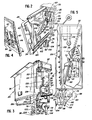
- Fig. 2 is a perspective view of one of the conveyor pockets with a portion broken away to show the mechanism for actuating the opener arm;
- Fig. 3 is a perspective view of a conveyor pocket showing in detail the end which attaches to the conveyor rail;
- Fig. 4 is a perspective view of the left side of Fig. 2 showing the linkage for pivoting the cam controlled plate member;
- Fig. 5 is an end view of a conveyor pocket showing the required elements for opening a newspaper to receive inner sections;
- Fig. 6 is a view in side elevation of a conveyor pocket showing by means of full and phantom lines the inactive and active positions respectively of the opener arm;
- Fig. 7 is a view similar to Fig. 5 showing a folded newspaper in the conveyor pocket in close proximity with the first panel member;
- Fig. 8 is a view similar to Fig. 7 showing the paper moved toward the second panel member by the cam controlled plate member;
- Fig. 9 is a view similar to Fig. 8 showing the levers with the vacuum controlled suction cups in position for forming the center opening for receiving the opener arm; and
- Fig. 10 is a view similar to Fig. 9 showing the opener arm in position for holding half' the paper in contact with the second panel member.
- Referring now to Fig. 1, there is shown the various mechanisms that form a newspaper assembler that is identified generally by
numeral 10. This assembler includes among its several mechanisms a pair of spacedstream markers 12 and 14, a gripper conveyor 16 andgripper loaders - A pocket carousel or endless conveyor with which the present invention is operatively associated is identified generally by
numeral 22 and is provided with a multiplicity of pockets of V-shaped configuration that are depicted generally bynumeral 24. - As shown in Fig. 2, a portion of the endless conveyor rail is shown at 26 and the
pockets 24 are caused to travel in their intended pathway by being operatively connected to anendless drive chain 28 that is disposed in operative engagement with a pair of spaced sprocket members 30 (one only shown). - As each of the
pockets 24 are identical and contain the same elements for preparing a folded newspaper to receive inner sections, it is considered sufficient to show and describe in detail only one such pocket. - As shown in Figs. 2 and 3, one end of the
pocket 24 defines asupport housing 32 which serves to attach it to theconveyor rail 26 and for housing various components of the invention yet to be described. Extending from the outer side of thesupport housing 32, the pocket is provided with first and second panel members identified bynumerals panel members newspaper 38 is adapted to be deposited (Figs. 7-10). A cam controlledplate member 40 is pivotably mounted on the upper ends of a pair of spacedfingers 42 and 44 (Fig. 6) as at 46 and 48 respectively. Thesefingers openings first panel 34 and their lower ends are fixed on ashaft 54 that is mounted for rotative movement inbearing blocks panel 34. Shaft 54 extends beyond thefirst panel 34 into thesupport housing 32 whereat it is operatively connected to acam follower 60 by means oflinkage members cam follower 60 is rotatably mounted on one end of asupport arm 66 as at 68. Thearm 66 is pivotably mounted within the support housing as at 70. As the pockets are caused to travel about their pathway, thecam follower 60 is caused to engage and then be disengaged from acam 72 mounted on the conveyor rail 26 (Figs. 8 and 9). Thecam 72 is effective in pivoting thecam follower 60 upwardly and, by means of thelinkage members fingers plate member 40 is pivoted from that position shown in Fig. 7 to that position shown in Fig. 8. As shown in Figs. 7 and 8, this movement is effective in moving the folded paper to a vertical position in contact with thesecond panel member 36. When the newspaper is in the position shown in Fig. 8, a mechanism now to be described is actuated to form acenter opening 74 at the fold portion as shown in Fig. 9. - The lower end of the
support housing 32 has a dependingsupport block 76 attached thereto which hasrod member 78 journaled therein for supporting agear element 80 and one end of alever 82 that carries acam follower 84 at its free end. As the pockets are caused to travel about their pathway, thecam follower 84 is also caused to engage and then disengage a cam 86 (Fig. 9) which is effective in rotating thegear element 80 in the direction of the indicatingarrow 88 in Fig. 9.Gear element 80 is in meshing relation with agear pinion 90 mounted on one end of asupport rod 92 that is journaled in thesupport block 76.Gear pinion 90 is also in meshing relation with anidentical gear pinion 94 mounted on one end of asupport rod 96 that is also journaled in thesupport block 76.Support rods 92 and 96' from theirrespective gear pinions support block 76 and at their free ends havefinger elements finger elements suction cups gear element 80 in the direction of the indicatingarrow 88 causesgear pinions gear pinions respective support rods finger elements suction cups finger elements 98 and 100 a sufficient distance so that the vacuum controlled suction cups are effective in pulling on the newspaper so as to form the center opening 74 at the fold. It should be noted that the vacuum cup apparatus described supra may not be necessary on the thicker jackets containing a pluage of sections. - When the
newspaper 38 is provided with the center opening 74 as shown in Fig. 9, a mechanisn now to be described is caused to swing anopener arm 106 into the center opening and thence upwardly to a position shown in Fig. 10 and the phantom line position in Fig. 6. - As shown in Figs. 2 and 6, one end of the
opener arm 106 is fixed on apin 108 for pivotable movement therewith which is journaled in and extends through asupport block 110 mounted within thesupport housing 32. The end of thepin 108 protruding through thesupport block 110 has agear pinion 112 fixed thereon that is disposed in meshing relation with arack gear 114. Thisrack gear 114 is mounted for vertical sliding movement within thesupport block 110 and has acam follower 116 rotatably mounted on the lower end thereof. During travel of the pockets about their pathway, thecam follower 116 is also caused to engage and disengage a cam 118 (Fig. 7) that is mounted on theconveyor rail 26. While thecam follower 116 is in contact with thecam 118 it is effective in maintaining theopener arm 106 in its inactive position which is that position depicted by solid lines in Fig. 6. - With reference to Figs. 2, 3, 7 and 10, a
coil spring 120 is shown having one end connected to the lower end of therack gear 114 and the opposite end to a pin 122 located within thesupport housing 32 below the rack gear. When thecam follower 116 loses contact withcam 118, thecoil spring 120 is effective in pulling therack gear 114 downwardly so as to effect rotation of thegear pinion 112 which, in turn, rotatespin 108 and swings theopener arm 106 into the center opening 74 and thence upwardly to the phantom line position shown in Fig. 6 whereat it is effective in holding one half of the newspaper in contact with thesecond.panel member 36. At this point,cam follower 60 loses contact withcam 72 which causes the cam controlledplate member 40 to return to its initial position of contact with thefirst panel member 34 and permits that half of the newspaper not being held by theopener arm 106 to drop back to the position shown in Fig. 10. With the two halves of the newspaper being in the position shown in Fig. 10, the paper is in readiness to receive the inner sections from a stuffing apparatus. - As shown in Figs. 2 and 5, the
opener arm 106 is provided with a plurality of tufts ofbristles 124 which are disposed in spaced relation along the length of the opener arm and serve to facilitate the opening of the paper by causing the soft bristles to engage and hold the paper rather than the opener itself. - After the newspapers have received their inner sections, a means is provided for releasing them from the pockets for further processing. As shown in Fig. 3, a
gate member 126 depends from asupport rod 128 that is located adjacent the lower edge of thesecond panel 36 and extends into thesupport housing 32 where the inner end thereof has anarm 130 fixed thereon. This arm is biased in a downwardly direction by acoil spring 132 and is provided with a pair ofcam followers 134 rotatably mounted on the free end thereof. These cam followers are adapted to engage a cam (not shown) that is also mounted on theconveyor rail 26 and is effective in swinging the gate member outwardly to release the newspaper from the pocket after theopener arm 106 has been returned to its solid line position shown in Fig. 6. - Although the present invention has been described in connection with a preferred embodiment, it is to be understood that modifications and variations may be resorted to without departing from the spirit and scope of the invention as those skilled in the art will readily understand. Such modifications and variations are considered to be within the purview and scope of the invention and the appended claims.
Claims (12)
Applications Claiming Priority (2)
| Application Number | Priority Date | Filing Date | Title |
|---|---|---|---|
| US06/450,592 US4496141A (en) | 1982-12-17 | 1982-12-17 | Method and apparatus for opening folded newspapers |
| US450592 | 1982-12-17 |
Publications (2)
| Publication Number | Publication Date |
|---|---|
| EP0118596A1 true EP0118596A1 (en) | 1984-09-19 |
| EP0118596B1 EP0118596B1 (en) | 1987-03-11 |
Family
ID=23788719
Family Applications (1)
| Application Number | Title | Priority Date | Filing Date |
|---|---|---|---|
| EP83111028A Expired EP0118596B1 (en) | 1982-12-17 | 1983-11-04 | Method and apparatus for opening folded newspapers |
Country Status (5)
| Country | Link |
|---|---|
| US (1) | US4496141A (en) |
| EP (1) | EP0118596B1 (en) |
| JP (1) | JPS59120496A (en) |
| CA (1) | CA1201676A (en) |
| DE (2) | DE3370148D1 (en) |
Cited By (5)
| Publication number | Priority date | Publication date | Assignee | Title |
|---|---|---|---|---|
| EP0218872A2 (en) * | 1985-09-27 | 1987-04-22 | Ferag AG | Device for gathering various printed products |
| EP0476859A2 (en) * | 1990-08-27 | 1992-03-25 | Graphic Management Associates, Inc. | Opener for folded printed products |
| EP0498935A1 (en) * | 1991-02-13 | 1992-08-19 | Graphic Management Associates, Inc. | Non-lap opener |
| EP0554801A1 (en) * | 1992-02-05 | 1993-08-11 | Graphic Management Associates, Inc. | Side opener |
| EP0834460A2 (en) * | 1996-09-25 | 1998-04-08 | Heidelberger Druckmaschinen Aktiengesellschaft | Sheet material collating system |
Families Citing this family (6)
| Publication number | Priority date | Publication date | Assignee | Title |
|---|---|---|---|---|
| CH669944A5 (en) * | 1986-04-04 | 1989-04-28 | Ferag Ag | |
| US4723770A (en) * | 1986-06-20 | 1988-02-09 | Graphic Management Associates, Inc. | Straight-line insert machine |
| US6276515B1 (en) | 1998-08-17 | 2001-08-21 | Harald M. Wayer | Steady-flow conveyor |
| US6655681B1 (en) | 2000-09-14 | 2003-12-02 | Heidelberger Druckmaschinen Ag | Sheet material conveying apparatus with individually-adjustable pockets |
| US6390469B1 (en) | 2000-10-30 | 2002-05-21 | Heidelberger Druckmaschinen Ag | Sheet material conveying apparatus with height-adjustable pockets |
| US6612567B1 (en) | 2002-06-24 | 2003-09-02 | Heidelberger Druckmaschinen Ag | Adjustable gripping device for adjustable sheet-receiving pockets |
Citations (5)
| Publication number | Priority date | Publication date | Assignee | Title |
|---|---|---|---|---|
| US3580562A (en) * | 1968-02-02 | 1971-05-25 | Ferag Ag | Apparatus for opening folded articles, such as newspapers |
| US3692301A (en) * | 1970-07-21 | 1972-09-19 | Ferag Ag | Method of,and apparatus for,opening folded multi-sheet paper products |
| US3722877A (en) * | 1970-01-09 | 1973-03-27 | Ferag Ag | Apparatus for opening folded bound multiple sheet paper products |
| US4116427A (en) * | 1976-02-19 | 1978-09-26 | Grapha-Holding Ag. | Apparatus for stuffing newspapers or the like |
| US4241908A (en) * | 1979-08-24 | 1980-12-30 | Marcus Joel A | Jacket clamping device for a paper stuffing machine |
Family Cites Families (6)
| Publication number | Priority date | Publication date | Assignee | Title |
|---|---|---|---|---|
| CH441391A (en) * | 1964-09-30 | 1967-08-15 | Graphicar Internationale Ausru | Device for the automatic nesting of folded printed products, for example booklets, sheets or newspapers, which are to be combined into a complete copy |
| US3752468A (en) * | 1970-10-27 | 1973-08-14 | Anpa | Apparatus to facilitate insertion of newspaper supplements |
| US3711083A (en) * | 1971-03-03 | 1973-01-16 | R Cantrell | Newspaper inserting machine |
| US3988016A (en) * | 1974-11-01 | 1976-10-26 | Cutler-Hammer, Inc. | High speed in-line paper inserting apparatus and method |
| US4373710A (en) * | 1980-08-22 | 1983-02-15 | Nolan Systems, Inc. | Apparatus for inserting supplementary material into newspaper jackets |
| CH649267A5 (en) * | 1980-11-17 | 1985-05-15 | Ferag Ag | METHOD AND DEVICE FOR INSERTING AT LEAST ONE INSERT IN PRINTED PRODUCTS. |
-
1982
- 1982-12-17 US US06/450,592 patent/US4496141A/en not_active Expired - Fee Related
-
1983
- 1983-10-28 CA CA000439996A patent/CA1201676A/en not_active Expired
- 1983-11-04 DE DE8383111028T patent/DE3370148D1/en not_active Expired
- 1983-11-04 DE DE198383111028T patent/DE118596T1/en active Pending
- 1983-11-04 EP EP83111028A patent/EP0118596B1/en not_active Expired
- 1983-12-15 JP JP58237141A patent/JPS59120496A/en active Pending
Patent Citations (5)
| Publication number | Priority date | Publication date | Assignee | Title |
|---|---|---|---|---|
| US3580562A (en) * | 1968-02-02 | 1971-05-25 | Ferag Ag | Apparatus for opening folded articles, such as newspapers |
| US3722877A (en) * | 1970-01-09 | 1973-03-27 | Ferag Ag | Apparatus for opening folded bound multiple sheet paper products |
| US3692301A (en) * | 1970-07-21 | 1972-09-19 | Ferag Ag | Method of,and apparatus for,opening folded multi-sheet paper products |
| US4116427A (en) * | 1976-02-19 | 1978-09-26 | Grapha-Holding Ag. | Apparatus for stuffing newspapers or the like |
| US4241908A (en) * | 1979-08-24 | 1980-12-30 | Marcus Joel A | Jacket clamping device for a paper stuffing machine |
Cited By (12)
| Publication number | Priority date | Publication date | Assignee | Title |
|---|---|---|---|---|
| EP0218872A2 (en) * | 1985-09-27 | 1987-04-22 | Ferag AG | Device for gathering various printed products |
| US4706951A (en) * | 1985-09-27 | 1987-11-17 | Ferag Ag | Apparatus for collating differentiated printed products |
| CH668245A5 (en) * | 1985-09-27 | 1988-12-15 | Ferag Ag | DEVICE FOR COMPILING DIFFERENT PRINTED PRODUCTS. |
| EP0218872A3 (en) * | 1985-09-27 | 1989-04-05 | Ferag Ag | Device for gathering various printed products |
| EP0476859A2 (en) * | 1990-08-27 | 1992-03-25 | Graphic Management Associates, Inc. | Opener for folded printed products |
| EP0476859A3 (en) * | 1990-08-27 | 1992-06-03 | Graphic Management Associates, Inc. | Opener for folded printed products |
| EP0596581A2 (en) | 1990-08-27 | 1994-05-11 | Graphic Management Associates, Inc. | Opener for folded printed products |
| EP0498935A1 (en) * | 1991-02-13 | 1992-08-19 | Graphic Management Associates, Inc. | Non-lap opener |
| EP0554801A1 (en) * | 1992-02-05 | 1993-08-11 | Graphic Management Associates, Inc. | Side opener |
| EP0834460A2 (en) * | 1996-09-25 | 1998-04-08 | Heidelberger Druckmaschinen Aktiengesellschaft | Sheet material collating system |
| EP0834460A3 (en) * | 1996-09-25 | 1998-08-05 | Heidelberger Druckmaschinen Aktiengesellschaft | Sheet material collating system |
| CN1064636C (en) * | 1996-09-25 | 2001-04-18 | 海德堡印刷机械股份公司 | Gathering system for sheetlike material |
Also Published As
| Publication number | Publication date |
|---|---|
| DE3370148D1 (en) | 1987-04-16 |
| JPS59120496A (en) | 1984-07-12 |
| US4496141A (en) | 1985-01-29 |
| DE118596T1 (en) | 1984-12-20 |
| CA1201676A (en) | 1986-03-11 |
| EP0118596B1 (en) | 1987-03-11 |
Similar Documents
| Publication | Publication Date | Title |
|---|---|---|
| US4496141A (en) | Method and apparatus for opening folded newspapers | |
| CA1091980A (en) | Method and means for breaking and separating eggs | |
| US4723770A (en) | Straight-line insert machine | |
| US4320615A (en) | Apparatus for the automatic filling of bags at the discharge spout of a filling hopper | |
| JPS62244840A (en) | Device for inserting appendixes to large number of print | |
| EP1197449B1 (en) | Device and method for transferring printed folded or unfolded paper sheets to a processing line | |
| DE2334071A1 (en) | COLLECTING DEVICE, IN PARTICULAR OPENING DEVICE FOR SIGNATURES | |
| US3662516A (en) | Box flap opener | |
| US3958505A (en) | Egg cracking machine | |
| CH461547A (en) | Device for opening multi-sheet, folded printed matter, in particular newspapers | |
| JPS58172132A (en) | Extractor for sheet material | |
| EP0598047A1 (en) | Transport/stacker module for mail processing system. | |
| CH625481A5 (en) | ||
| US2355697A (en) | Sheet delivery mechanism | |
| US4116427A (en) | Apparatus for stuffing newspapers or the like | |
| FI92683C (en) | Straight feeder | |
| JPH10212025A (en) | Transfer device for fragile article such as egg | |
| DE2629064C3 (en) | Device for forming and transporting packages from bags deposited by the rotating depositing cylinder of a bag machine | |
| EP0688682A1 (en) | Apparatus for unfolding documents | |
| DE2534583C3 (en) | Device for dispensing vessels, in particular bottles | |
| EP0095576A2 (en) | Newspaper container loading apparatus | |
| EP1149791A2 (en) | Device for removing a test sheet in a delivery apparatus of a sheet printing machine | |
| US848784A (en) | Machine for shucking oysters. | |
| DE2130954B2 (en) | Device for transferring bags | |
| EP0113286B1 (en) | Jogging and stacking table for sheet-like articles, especially stacks of paper sheets |
Legal Events
| Date | Code | Title | Description |
|---|---|---|---|
| PUAI | Public reference made under article 153(3) epc to a published international application that has entered the european phase |
Free format text: ORIGINAL CODE: 0009012 |
|
| AK | Designated contracting states |
Designated state(s): CH DE GB LI SE |
|
| DET | De: translation of patent claims | ||
| 17P | Request for examination filed |
Effective date: 19841113 |
|
| GRAA | (expected) grant |
Free format text: ORIGINAL CODE: 0009210 |
|
| AK | Designated contracting states |
Kind code of ref document: B1 Designated state(s): CH DE GB LI SE |
|
| REF | Corresponds to: |
Ref document number: 3370148 Country of ref document: DE Date of ref document: 19870416 |
|
| PLBE | No opposition filed within time limit |
Free format text: ORIGINAL CODE: 0009261 |
|
| STAA | Information on the status of an ep patent application or granted ep patent |
Free format text: STATUS: NO OPPOSITION FILED WITHIN TIME LIMIT |
|
| 26N | No opposition filed | ||
| PG25 | Lapsed in a contracting state [announced via postgrant information from national office to epo] |
Ref country code: GB Effective date: 19891104 |
|
| PG25 | Lapsed in a contracting state [announced via postgrant information from national office to epo] |
Ref country code: SE Effective date: 19891105 |
|
| PG25 | Lapsed in a contracting state [announced via postgrant information from national office to epo] |
Ref country code: LI Effective date: 19891130 Ref country code: CH Effective date: 19891130 |
|
| GBPC | Gb: european patent ceased through non-payment of renewal fee | ||
| REG | Reference to a national code |
Ref country code: CH Ref legal event code: PL |
|
| PG25 | Lapsed in a contracting state [announced via postgrant information from national office to epo] |
Ref country code: DE Effective date: 19900801 |
|
| EUG | Se: european patent has lapsed |
Ref document number: 83111028.3 Effective date: 19900705 |