EP0118239A2 - Kohlefaserstrukturen - Google Patents
Kohlefaserstrukturen Download PDFInfo
- Publication number
- EP0118239A2 EP0118239A2 EP84300921A EP84300921A EP0118239A2 EP 0118239 A2 EP0118239 A2 EP 0118239A2 EP 84300921 A EP84300921 A EP 84300921A EP 84300921 A EP84300921 A EP 84300921A EP 0118239 A2 EP0118239 A2 EP 0118239A2
- Authority
- EP
- European Patent Office
- Prior art keywords
- electrically conductive
- fibre
- shim
- layer
- fibres
- Prior art date
- Legal status (The legal status is an assumption and is not a legal conclusion. Google has not performed a legal analysis and makes no representation as to the accuracy of the status listed.)
- Granted
Links
Images

Classifications
-
- H—ELECTRICITY
- H01—ELECTRIC ELEMENTS
- H01Q—ANTENNAS, i.e. RADIO AERIALS
- H01Q9/00—Electrically-short antennas having dimensions not more than twice the operating wavelength and consisting of conductive active radiating elements
- H01Q9/04—Resonant antennas
- H01Q9/30—Resonant antennas with feed to end of elongated active element, e.g. unipole
- H01Q9/32—Vertical arrangement of element
- H01Q9/38—Vertical arrangement of element with counterpoise
-
- H—ELECTRICITY
- H01—ELECTRIC ELEMENTS
- H01B—CABLES; CONDUCTORS; INSULATORS; SELECTION OF MATERIALS FOR THEIR CONDUCTIVE, INSULATING OR DIELECTRIC PROPERTIES
- H01B1/00—Conductors or conductive bodies characterised by the conductive materials; Selection of materials as conductors
- H01B1/20—Conductive material dispersed in non-conductive organic material
- H01B1/24—Conductive material dispersed in non-conductive organic material the conductive material comprising carbon-silicon compounds, carbon or silicon
-
- H—ELECTRICITY
- H01—ELECTRIC ELEMENTS
- H01Q—ANTENNAS, i.e. RADIO AERIALS
- H01Q1/00—Details of, or arrangements associated with, antennas
- H01Q1/48—Earthing means; Earth screens; Counterpoises
-
- Y—GENERAL TAGGING OF NEW TECHNOLOGICAL DEVELOPMENTS; GENERAL TAGGING OF CROSS-SECTIONAL TECHNOLOGIES SPANNING OVER SEVERAL SECTIONS OF THE IPC; TECHNICAL SUBJECTS COVERED BY FORMER USPC CROSS-REFERENCE ART COLLECTIONS [XRACs] AND DIGESTS
- Y10—TECHNICAL SUBJECTS COVERED BY FORMER USPC
- Y10T—TECHNICAL SUBJECTS COVERED BY FORMER US CLASSIFICATION
- Y10T428/00—Stock material or miscellaneous articles
- Y10T428/24—Structurally defined web or sheet [e.g., overall dimension, etc.]
- Y10T428/24058—Structurally defined web or sheet [e.g., overall dimension, etc.] including grain, strips, or filamentary elements in respective layers or components in angular relation
- Y10T428/24074—Strand or strand-portions
- Y10T428/24091—Strand or strand-portions with additional layer[s]
- Y10T428/24099—On each side of strands or strand-portions
-
- Y—GENERAL TAGGING OF NEW TECHNOLOGICAL DEVELOPMENTS; GENERAL TAGGING OF CROSS-SECTIONAL TECHNOLOGIES SPANNING OVER SEVERAL SECTIONS OF THE IPC; TECHNICAL SUBJECTS COVERED BY FORMER USPC CROSS-REFERENCE ART COLLECTIONS [XRACs] AND DIGESTS
- Y10—TECHNICAL SUBJECTS COVERED BY FORMER USPC
- Y10T—TECHNICAL SUBJECTS COVERED BY FORMER US CLASSIFICATION
- Y10T428/00—Stock material or miscellaneous articles
- Y10T428/24—Structurally defined web or sheet [e.g., overall dimension, etc.]
- Y10T428/24058—Structurally defined web or sheet [e.g., overall dimension, etc.] including grain, strips, or filamentary elements in respective layers or components in angular relation
- Y10T428/24124—Fibers
-
- Y—GENERAL TAGGING OF NEW TECHNOLOGICAL DEVELOPMENTS; GENERAL TAGGING OF CROSS-SECTIONAL TECHNOLOGIES SPANNING OVER SEVERAL SECTIONS OF THE IPC; TECHNICAL SUBJECTS COVERED BY FORMER USPC CROSS-REFERENCE ART COLLECTIONS [XRACs] AND DIGESTS
- Y10—TECHNICAL SUBJECTS COVERED BY FORMER USPC
- Y10T—TECHNICAL SUBJECTS COVERED BY FORMER US CLASSIFICATION
- Y10T428/00—Stock material or miscellaneous articles
- Y10T428/24—Structurally defined web or sheet [e.g., overall dimension, etc.]
- Y10T428/24802—Discontinuous or differential coating, impregnation or bond [e.g., artwork, printing, retouched photograph, etc.]
- Y10T428/24826—Spot bonds connect components
-
- Y—GENERAL TAGGING OF NEW TECHNOLOGICAL DEVELOPMENTS; GENERAL TAGGING OF CROSS-SECTIONAL TECHNOLOGIES SPANNING OVER SEVERAL SECTIONS OF THE IPC; TECHNICAL SUBJECTS COVERED BY FORMER USPC CROSS-REFERENCE ART COLLECTIONS [XRACs] AND DIGESTS
- Y10—TECHNICAL SUBJECTS COVERED BY FORMER USPC
- Y10T—TECHNICAL SUBJECTS COVERED BY FORMER US CLASSIFICATION
- Y10T428/00—Stock material or miscellaneous articles
- Y10T428/249921—Web or sheet containing structurally defined element or component
- Y10T428/249924—Noninterengaged fiber-containing paper-free web or sheet which is not of specified porosity
- Y10T428/24994—Fiber embedded in or on the surface of a polymeric matrix
- Y10T428/249942—Fibers are aligned substantially parallel
- Y10T428/249945—Carbon or carbonaceous fiber
-
- Y—GENERAL TAGGING OF NEW TECHNOLOGICAL DEVELOPMENTS; GENERAL TAGGING OF CROSS-SECTIONAL TECHNOLOGIES SPANNING OVER SEVERAL SECTIONS OF THE IPC; TECHNICAL SUBJECTS COVERED BY FORMER USPC CROSS-REFERENCE ART COLLECTIONS [XRACs] AND DIGESTS
- Y10—TECHNICAL SUBJECTS COVERED BY FORMER USPC
- Y10T—TECHNICAL SUBJECTS COVERED BY FORMER US CLASSIFICATION
- Y10T428/00—Stock material or miscellaneous articles
- Y10T428/30—Self-sustaining carbon mass or layer with impregnant or other layer
-
- Y—GENERAL TAGGING OF NEW TECHNOLOGICAL DEVELOPMENTS; GENERAL TAGGING OF CROSS-SECTIONAL TECHNOLOGIES SPANNING OVER SEVERAL SECTIONS OF THE IPC; TECHNICAL SUBJECTS COVERED BY FORMER USPC CROSS-REFERENCE ART COLLECTIONS [XRACs] AND DIGESTS
- Y10—TECHNICAL SUBJECTS COVERED BY FORMER USPC
- Y10T—TECHNICAL SUBJECTS COVERED BY FORMER US CLASSIFICATION
- Y10T428/00—Stock material or miscellaneous articles
- Y10T428/31504—Composite [nonstructural laminate]
- Y10T428/31678—Of metal
Definitions
- This invention relates to carbon fibre structures and particularly to resin bonded carbon fibre structures having a surface area portion adapted to provide a low electrical impedance connection, and to methods of providing such a connection.
- the problem manifests itself, for example, in the mounting of a radio antenna which requires a good electrical connection in order to inject, through a base connection, high R.F. currents into the fuselage surface which then acts as a ground plane or counterpoise.
- a poor connection produces heat and lowers the overall efficiency of the system, and the problem is particularly relevant in the H.F. range of radio frequencies (2-30 MHz).
- the invention provides a resin bonded carbon fibre structure having a portion of its surface area adapted to provide a low electrical impedance connection for mounting a device such as a radio antenna characterised in that said surface area portion comprises an exposed dimpled electrically conductive metal shim bonded to the structure.
- the shim may comprise nickel plated brass.
- a ply of unidirectional carbon fibres coated with an electrically conductive material may be located between the shim and the outer carbon fibre layer of the structure and, preferably, the fibre orientation in the said ply of coated carbon fibres is at 90 degrees to the fibres of the outer carbon fibre layer.
- the electrically conductive coating material may constitute a uniform and concentric coating of electroplated nickel.
- the invention provides a method of providing a low electrical impedance connection on to a pre-cured resin bonded carbon fibre composite structure, comprising the steps of abrading an area of the structure of the desired size and shape so as to remove the external resin layer and expose a layer of carbon fibres, cutting one ply of an electrically conductive pre-impregnated unidirectional fibre material to the shape of the abraded area, applying the electrically conductive fibre material on to the abraded area, so that its fibre orientation is at 90 degrees to the exposed carbon fibres of the structure, cutting a dimpled electrically conductive metal shim to a desired size and shape and locating it over the electrically conductive fibre material with the dimples in engagement therewith, and bonding the electrically conductive fibre material and the shim on to the structure.
- the invention provides a method of attaching a radic antenna on to a resin bonded carbon fibre structure, comprising the steps of cutting antenna attachment holes and apertures for tuning logic and RF input connections through the structure, abrading an area of the outer surface of the structure at least as large as the footprint area of the antenna to remove -the resin layer and expose a layer Of fibres, cutting a ply of an electrically conductive pre-impregnated unidirectional fibre material to fit the abraded area and applying it to the structure so that the fibre orientation of the conductive material ply is at 90 degrees to that of the exposed carbon fibres, cutting a lightly dimpled electrically conductive metal shim so as to fit the abraded area and locating the shim with its dimples engaging the electrically conductive fibre material, bonding the ply of electrically conductive fibre material and the shim on to the exposed fibre layer, locating an RF gasket and the antenna on the shim and securing the antenna with attachment bolts.
- the electrically conductive fibre material comprises carbon fibres uniformly and concentrically coated with electroplated nickel, and the metal shim comprises nickel plated brass.
- a typical fibre reinforced structural panel 20 for use in aircraft construction consists of an aluminium or paper honeycomb core 21 sandwiched between outer sheets 22 and 23 each comprising a plurality of layers of pre-impregnated unidirectional carbon fibres.
- the structure is consolidated and cured by the application of heat and pressure.
- connection resistance between the RF gasket and the fuselage surface should be not greater than about 1 milli-ohm (m ⁇ ). Whilst this is relatively easy to achieve on the metal skin it is considered that an RF gasket bolted on to the resin rich outer surface of the composite panel of Figure 1 would result in a connection resistance several orders of magnitude higher.
- test samples of Figures 2 to 4 is about 10.16 cm (4.0 in) square and it will be understood that the thickness of the respective layers has been greatly enlarged in the drawings in order to clarify the construction.
- Sample 1 consists of a plain sheet of 0.050 mm (0.002 in) thick electrically conductive metal shim 10 such as nickel plated.brass, two layers 11 and 12 of 0.127 mm (0.005 in) thick pre-impregnated unidirectional carbon fibre material arranged at 90 degrees to each other, a second plain nickel plated brass shim 13, a single layer 14 of 0.127 mm (0.005 in) thick pre-impregnated unidirectional carbon fibre material and a third plain nickel plated brass shim 15.
- the assembly was then cured at a temperature of 248°F (120 0 C) for one hour and at a consolidating pressure of 1.75 kg/sq cm (25 psi).
- Sample 2 was identical to Sample 1 except-that the sheets 10, 13 and 15 of electrically conductive metal shim were lightly dimpled nickel plated brass shim. Sheets 10 and 15 were dimpled from one side only and arranged with the dimples protruding into the adjacent carbon fibre layer and sheet 13 was dimpled from both sides.
- the measured height of the dimples from the surface of the sheet was approximately 0.050 mm (0.002 in) with a spacing of approximately 2.54 mm (0.1 in).
- Sample 3 consisted of a lower dimpled nickel plated brass shim 16 on to which one layer 17 of 0.127 mm (0.005 in) thick pre-impregnated unidirectional carbon fibre material was bonded under a consolidating pressure of 1.75 kg/sq cm (25 psi) at a temperature of 284 0 F (140 0 C) for one hour. After curing, the outer surface of layer 17 was abraded using wet and dry paper to remove the layer of cured resin and expose the carbon fibres.
- a layer of electrically conductive fibre reinforced material 18 comprising a further layer of 0.127 mm (0.005 in) thick pre-impregnated unidirectional carbon fibre reinforced material was then laid on to the exposed fibres of layer 17 with the direction of its fibres at 90 degrees to those of layer 17. It was considered that this orientation of fibres would provide for improved electrical contact under a consolidation pressure.
- Layer 18 was covered by a further dimpled nickel plated brass shim 19 and bonded to the pre-cured layer 17 at a temperature of 350°F (177°C) and a consolidation pressure of 1.75 kg/sq cm (25 psi) for 2 hours. It will be understood that bonding is achieved by curing of the impregnating resin in layer 18.
- Sample 4 was identical to Sample 3 except that layer 18 was replaced by an electrically conductive layer comprising a pre-impregnated unidirectional layer in which the carbon fibres had been uniformly and concentrically coated with an electrically conductive material such as electroplated nickel.
- an electrically conductive material such as electroplated nickel.
- Such material is available under the Trade Name CYMET from Cyanamid Fothergill, and it will be understood again that bonding is achieved by using the impregnating resin.
- the electrical resistance at D was measured and is shown in Table 2.
- Sample 5 was identical to Sample 4 except that the components were co-cured, i.e. the assembly was cured in a single curing operation, so as to be representative of a mounting incorporated during manufacture of a carbon fibre panel.
- the electrical resistance at D is again shown in Table 2.
- the resistance in Samples 4 and 5 using the nickel plated fibre material is about one half of the resistance of Sample 3 in which the electrically conductive layer comprised a layer of conventional pre-impregnated unidirectional carbon fibres.
- the nickel plated brass shim can, when compared to the carbon fibre panel, be considered a perfect conductor and therefore ignored.
- Sample 5 which was identical to Sample 4 except that the components were co-cured, i.e. were all cured in one curing cycle.
- connection resistance is below the value of 1 m ⁇ .
- the method of this invention is capable of providing an electrical connection on to a carbon fibre panel whose resistance is comparable with that normally achieved on a metallic fuselage. It has also been shown that the method is applicable to carbon fibre structures both during the manufacturing stage as well as to panels that have previously been cured.
- This procedure is similar to procedure 1 except that the outermost fibre layer at least in the area of the shim consists of pre-impregnated unidirectional fibre material in which the fibres are electrically conductive e.g. carbon, and are coated with a uniform and concentric layer of electrically conductive material e.g. electroplated nickel.
- the fibres of the electrically conductive layer are located at 90 degrees to the fibres of the carbon fibre layer which it contacts.
- the mounting is completed by a electrically conductive metal shim.
- the invention also extends to a method of either incorporating a low impedance connection or repairing an existing connection on a carbon fibre structure in the field, and for this purpose a portable membrane box and heater mat is proposed (Figure 5).
- the box 24 comprises a metal frame 25 carrying a flexible rubber membrane 26 and incorporating a pressure gauge 27 and compressed air inlet connection 28.
- a load spreader plate 29 is located on the opposite side of the structure 30 and the box 24 is secured by bolts passing through apertures 31 formed through the structure either for attachment bolts for the device to be mounted on the structure or in the case of an HF antenna, for tuning logic and RF input connection.
- the procedure is similar to that of procedure 3, i.e. a layer of pre-impregnated electrically conductive fibre material 39 followed by a dimpled electrically conductive metal shim 40 is laid up on the abraded area of the structure 30.
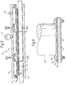
- Figure 6 illustrates a resin bonded carbon fibre structure having a portion of its surface area prepared in accordance with one of the methods hereinbefore described in order to provide a low electrical impedance connection, and in use in a practical installation for the attachment of a radio antenna.
- the structure comprises a sandwich of honeycomb material 32 between skins 33 each consisting of a plurality of layers of resin bonded carbon fibres.
- a conventional RF gasket 37 is located on the shim and the antenna 35 is attached to the structure by bolts 38 through an integral flange portion.
Landscapes
- Physics & Mathematics (AREA)
- Chemical & Material Sciences (AREA)
- Dispersion Chemistry (AREA)
- Spectroscopy & Molecular Physics (AREA)
- Laminated Bodies (AREA)
Applications Claiming Priority (2)
| Application Number | Priority Date | Filing Date | Title |
|---|---|---|---|
| GB8305161 | 1983-02-24 | ||
| GB8305161 | 1983-02-24 |
Publications (3)
| Publication Number | Publication Date |
|---|---|
| EP0118239A2 true EP0118239A2 (de) | 1984-09-12 |
| EP0118239A3 EP0118239A3 (en) | 1986-01-15 |
| EP0118239B1 EP0118239B1 (de) | 1990-08-01 |
Family
ID=10538538
Family Applications (1)
| Application Number | Title | Priority Date | Filing Date |
|---|---|---|---|
| EP19840300921 Expired - Lifetime EP0118239B1 (de) | 1983-02-24 | 1984-02-14 | Kohlefaserstrukturen |
Country Status (3)
| Country | Link |
|---|---|
| US (1) | US4507341A (de) |
| EP (1) | EP0118239B1 (de) |
| DE (1) | DE3482841D1 (de) |
Cited By (2)
| Publication number | Priority date | Publication date | Assignee | Title |
|---|---|---|---|---|
| WO1991003847A1 (en) * | 1989-08-29 | 1991-03-21 | Hughes Aircraft Company | Graphite composite structures exhibiting electrical conductivity |
| KR101128771B1 (ko) * | 2011-12-30 | 2012-03-23 | 주식회사 대진디엠피 | 고정형 led등기구 |
Families Citing this family (13)
| Publication number | Priority date | Publication date | Assignee | Title |
|---|---|---|---|---|
| US4609586A (en) * | 1984-08-02 | 1986-09-02 | The Boeing Company | Thermally conductive printed wiring board laminate |
| FR2596136B1 (fr) * | 1986-03-21 | 1988-09-16 | Bronzavia Air Equipement | Cloison d'isolation thermique et son application a la realisation d'un dispositif d'isolation thermique |
| WO1991020107A1 (en) * | 1990-06-12 | 1991-12-26 | Bell Helicopter Textron, Inc. | Automatic direction finder sense antenna |
| US6454276B2 (en) * | 1992-08-19 | 2002-09-24 | The Boeing Company | Corrosion resistant gasket for aircraft |
| JPH0855648A (ja) * | 1994-08-12 | 1996-02-27 | Shinano Polymer Kk | エラストマーコネクター |
| US7014143B2 (en) * | 2002-10-11 | 2006-03-21 | The Boeing Company | Aircraft lightning strike protection and grounding technique |
| CA2773620C (en) * | 2009-09-09 | 2016-01-12 | Turbosonic Inc. | Assembly of wet electrostatic precipitator |
| US9387487B2 (en) | 2011-03-28 | 2016-07-12 | Megtec Turbosonic Inc. | Erosion-resistant conductive composite material collecting electrode for WESP |
| JP5972376B2 (ja) * | 2011-08-17 | 2016-08-17 | ビー イー エアロスペイス,インク. | 埋込みインサートを備えた高強度航空機インテリアパネル |
| US11027289B2 (en) | 2011-12-09 | 2021-06-08 | Durr Systems Inc. | Wet electrostatic precipitator system components |
| US9502755B2 (en) | 2014-01-24 | 2016-11-22 | GM Global Technology Operations LLC | Automotive radio antenna and method for making the same |
| CN112279563B (zh) * | 2020-10-20 | 2022-06-21 | 南方科技大学 | 可控压缩形变法取向碳纤维制备纵向高导热垫片的制备方法 |
| CN112909510B (zh) * | 2021-01-27 | 2022-11-25 | 宇联星程(浙江)科技有限公司 | 一种碳纤维镀银导电碳纤维复合材料天线 |
Family Cites Families (8)
| Publication number | Priority date | Publication date | Assignee | Title |
|---|---|---|---|---|
| DE2119567C2 (de) * | 1970-05-05 | 1983-07-14 | International Computers Ltd., London | Elektrische Verbindungsvorrichtung und Verfahren zu ihrer Herstellung |
| US3680037A (en) * | 1970-11-05 | 1972-07-25 | Tech Wire Prod Inc | Electrical interconnector |
| NL152716B (nl) * | 1973-08-08 | 1977-03-15 | Amp Inc | Elektrisch verbindingsorgaan voor het losneembaar verbinden van twee ter weerszijden daarvan te plaatsen vaste contactdragers en werkwijze voor het vervaardigen van een dergelijk elektrisch verbindingsorgaan. |
| NL158033B (nl) * | 1974-02-27 | 1978-09-15 | Amp Inc | Verbetering van een elektrisch verbindingsorgaan voor het losneembaar verbinden van twee vaste contactdragers en werkwijze voor het vervaardigen van zulk een elektrisch verbindingsorgaan. |
| FR2312864A1 (fr) * | 1975-05-29 | 1976-12-24 | Etud Rech Chimique Lab | Antenne radio-electrique composite, specialement antenne d'emission |
| US4134120A (en) * | 1976-10-12 | 1979-01-09 | Coastal Engineered Products Company, Inc. | Whip antenna formed of electrically conductive graphite strands embedded in a resin material |
| US4199209A (en) * | 1978-08-18 | 1980-04-22 | Amp Incorporated | Electrical interconnecting device |
| US4231041A (en) * | 1979-06-18 | 1980-10-28 | General Motors Corporation | Electrically conducting lead termination apparatus for a thin film antenna |
-
1984
- 1984-02-14 EP EP19840300921 patent/EP0118239B1/de not_active Expired - Lifetime
- 1984-02-14 DE DE8484300921T patent/DE3482841D1/de not_active Expired - Lifetime
- 1984-02-17 US US06/581,191 patent/US4507341A/en not_active Expired - Fee Related
Cited By (2)
| Publication number | Priority date | Publication date | Assignee | Title |
|---|---|---|---|---|
| WO1991003847A1 (en) * | 1989-08-29 | 1991-03-21 | Hughes Aircraft Company | Graphite composite structures exhibiting electrical conductivity |
| KR101128771B1 (ko) * | 2011-12-30 | 2012-03-23 | 주식회사 대진디엠피 | 고정형 led등기구 |
Also Published As
| Publication number | Publication date |
|---|---|
| EP0118239B1 (de) | 1990-08-01 |
| EP0118239A3 (en) | 1986-01-15 |
| US4507341A (en) | 1985-03-26 |
| DE3482841D1 (de) | 1990-09-06 |
Similar Documents
| Publication | Publication Date | Title |
|---|---|---|
| US4507341A (en) | Carbon fibre structures | |
| US4249976A (en) | Manufacture of honeycomb sandwich | |
| US7109943B2 (en) | Structurally integrated antenna aperture and fabrication method | |
| US5225265A (en) | Environmentally durable lightning strike protection materials for composite structures | |
| US3768760A (en) | Graphite fiber composite covering employing multi-directional | |
| US3806928A (en) | Laminated sandwich construction | |
| JP5089592B2 (ja) | 落雷保護用の銅グリッド修復技術 | |
| US5344685A (en) | Production of composite sandwich structures | |
| JP2731848B2 (ja) | 複合材料物品の製造方法 | |
| US9318812B2 (en) | Antenna fabrication | |
| US20060097944A1 (en) | Design and fabrication methodology for a phased array antenna with shielded/integrated structure | |
| EP0835049A2 (de) | Gerät und Verfahren zur Beschaffung einer leitenden korrosionsbeständigen Strecke durch nichtleitenden Fügen und zwischenräume | |
| EP1085611A1 (de) | Verfahren zum Anschliessen zwei Sätzen von Elektrodenanschlüssen auf einer Leiterplatte | |
| US20090148681A1 (en) | Radome and method of producing the same | |
| US20110186206A1 (en) | Copper grid repair technique for lightning strike protection | |
| US20020119028A1 (en) | Hot melt fastener filler | |
| US6126061A (en) | Element made of composite material including electrical continuity through the element | |
| EP3592107B1 (de) | Beheizte bodenplatten | |
| WO1992000845A1 (en) | Manufacture of a composite material | |
| US10848189B2 (en) | Method for curing and embedding an antenna in a composite part | |
| US7283095B2 (en) | Antenna assembly including z-pinning for electrical continuity | |
| US2643320A (en) | Heating element | |
| JP2017171276A (ja) | 構造的アンテナアレイ、及び構造的アンテナアレイを作製する方法 | |
| CN113928576A (zh) | 一种直升机复合材料雷电防护能力修复方法 | |
| DE102017202751A1 (de) | Raumfahrtsystem |
Legal Events
| Date | Code | Title | Description |
|---|---|---|---|
| PUAI | Public reference made under article 153(3) epc to a published international application that has entered the european phase |
Free format text: ORIGINAL CODE: 0009012 |
|
| AK | Designated contracting states |
Designated state(s): DE FR GB IT |
|
| PUAL | Search report despatched |
Free format text: ORIGINAL CODE: 0009013 |
|
| AK | Designated contracting states |
Designated state(s): DE FR GB IT |
|
| 17P | Request for examination filed |
Effective date: 19860613 |
|
| RAP1 | Party data changed (applicant data changed or rights of an application transferred) |
Owner name: WESTLAND GROUP PLC |
|
| 17Q | First examination report despatched |
Effective date: 19880906 |
|
| ITF | It: translation for a ep patent filed | ||
| GRAA | (expected) grant |
Free format text: ORIGINAL CODE: 0009210 |
|
| AK | Designated contracting states |
Kind code of ref document: B1 Designated state(s): DE FR GB IT |
|
| REF | Corresponds to: |
Ref document number: 3482841 Country of ref document: DE Date of ref document: 19900906 |
|
| ET | Fr: translation filed | ||
| PGFP | Annual fee paid to national office [announced via postgrant information from national office to epo] |
Ref country code: GB Payment date: 19910204 Year of fee payment: 8 |
|
| PGFP | Annual fee paid to national office [announced via postgrant information from national office to epo] |
Ref country code: FR Payment date: 19910212 Year of fee payment: 8 |
|
| ITTA | It: last paid annual fee | ||
| PGFP | Annual fee paid to national office [announced via postgrant information from national office to epo] |
Ref country code: DE Payment date: 19910228 Year of fee payment: 8 |
|
| PLBE | No opposition filed within time limit |
Free format text: ORIGINAL CODE: 0009261 |
|
| STAA | Information on the status of an ep patent application or granted ep patent |
Free format text: STATUS: NO OPPOSITION FILED WITHIN TIME LIMIT |
|
| 26N | No opposition filed | ||
| PG25 | Lapsed in a contracting state [announced via postgrant information from national office to epo] |
Ref country code: GB Effective date: 19920214 |
|
| GBPC | Gb: european patent ceased through non-payment of renewal fee | ||
| PG25 | Lapsed in a contracting state [announced via postgrant information from national office to epo] |
Ref country code: FR Effective date: 19921030 |
|
| PG25 | Lapsed in a contracting state [announced via postgrant information from national office to epo] |
Ref country code: DE Effective date: 19921103 |
|
| REG | Reference to a national code |
Ref country code: FR Ref legal event code: ST |