EP0117844A2 - Druckregelventil mit elektrischer Kontrolle - Google Patents
Druckregelventil mit elektrischer Kontrolle Download PDFInfo
- Publication number
- EP0117844A2 EP0117844A2 EP84810035A EP84810035A EP0117844A2 EP 0117844 A2 EP0117844 A2 EP 0117844A2 EP 84810035 A EP84810035 A EP 84810035A EP 84810035 A EP84810035 A EP 84810035A EP 0117844 A2 EP0117844 A2 EP 0117844A2
- Authority
- EP
- European Patent Office
- Prior art keywords
- pressure
- secondary pressure
- electrical
- pressure control
- control valve
- Prior art date
- Legal status (The legal status is an assumption and is not a legal conclusion. Google has not performed a legal analysis and makes no representation as to the accuracy of the status listed.)
- Granted
Links
Images
Classifications
-
- G—PHYSICS
- G05—CONTROLLING; REGULATING
- G05D—SYSTEMS FOR CONTROLLING OR REGULATING NON-ELECTRIC VARIABLES
- G05D16/00—Control of fluid pressure
- G05D16/04—Control of fluid pressure without auxiliary power
- G05D16/06—Control of fluid pressure without auxiliary power the sensing element being a flexible membrane, yielding to pressure, e.g. diaphragm, bellows, capsule
- G05D16/063—Control of fluid pressure without auxiliary power the sensing element being a flexible membrane, yielding to pressure, e.g. diaphragm, bellows, capsule the sensing element being a membrane
- G05D16/0644—Control of fluid pressure without auxiliary power the sensing element being a flexible membrane, yielding to pressure, e.g. diaphragm, bellows, capsule the sensing element being a membrane the membrane acting directly on the obturator
- G05D16/0663—Control of fluid pressure without auxiliary power the sensing element being a flexible membrane, yielding to pressure, e.g. diaphragm, bellows, capsule the sensing element being a membrane the membrane acting directly on the obturator using a spring-loaded membrane with a spring-loaded slideable obturator
- G05D16/0669—Control of fluid pressure without auxiliary power the sensing element being a flexible membrane, yielding to pressure, e.g. diaphragm, bellows, capsule the sensing element being a membrane the membrane acting directly on the obturator using a spring-loaded membrane with a spring-loaded slideable obturator characterised by the loading mechanisms of the membrane
Definitions
- Pressure regulating valves and pressure switches are known pneumatic devices. Pressure control valves reduce the primary pressure (network pressure) to a desired secondary pressure (operating pressure) and keep this value largely constant, regardless of air consumption and primary pressure fluctuations.
- Pressure switches have the task of switching an electrical circuit on or off when a certain pneumatic pressure is reached.
- the secondary pressure set with a pressure control valve can be monitored with a pressure switch by connecting the pressure switch to the secondary circuit.
- the pressure switch must also be reset. This takes a lot of time and if the pressure switch is reset incorrectly or even forgotten, malfunctions and accidents can result.
- the object of the invention was to create a pressure control valve in which an electrical signal is emitted as soon as the set secondary pressure drops by a certain amount dp in such a way that only the secondary pressure has to be set on the electrical pressure monitor itself, but no readjustment is required.
- this object is achieved according to the invention by a design in which the opening path of a valve plate is used for electrical secondary pressure monitoring.
- the pressure control valve itself works in a known manner as a P controller.
- the primary pressure occurs at 1.
- an adjusting spring 4 is now tensioned and a diaphragm 5 is pressed downwards. It actuates a valve actuation pin 6 and a valve disk 7 lifts off from the valve seat 8.
- the compressed air now flows through the resulting annular gap into secondary pressure chamber 2 and reaches outlet 3 at outlet 3. If no removal takes place, a pressure also builds up in the secondary pressure chamber 2 and pushes the membrane 5 up again.
- valve plate 7 is pressed back onto its seat 8 and the valve closes.
- the pressure in secondary pressure chamber 2 drops, the spring force outweighs the membrane force and the valve opens again.
- valve plate 7 The opening travel of the valve plate 7 is now proportional to the pressure difference dp between the set secondary pressure and the pressure actually prevailing in the secondary pressure chamber 2. This fact is now used according to the invention for electrical pressure control.
- the adjusting spring 4 acts on the diaphragm 5 via a guide piston 9.
- the guide piston 9 and a pin 10 pressed into it thus make the same path dependent on ⁇ p as the diaphragm 5, the valve actuating pin 6 and the valve plate 7.
Landscapes
- Physics & Mathematics (AREA)
- Fluid Mechanics (AREA)
- General Physics & Mathematics (AREA)
- Engineering & Computer Science (AREA)
- Automation & Control Theory (AREA)
- Control Of Fluid Pressure (AREA)
Abstract
Description
- Druckregelventile und Druckschalter sind bekannte pneumatische Geräte. Druckregelventile reduzieren den Primärdruck (Netzdruck) auf einen gewünschten Sekundärdruck (Betriebsdruck) und halten diesen Wert weitgehend konstant, unabhängig vom Luftverbrauch und von Primärdruck-Schwankungen.
- Druckschalter haben die Aufgabe, beim Erreichen eines bestimmten pneumatischen Druckes einen elektrischen Stromkreis ein- bzw. auszuschalten. Somit kann mit einem Druckschalter der mit einem Druckregelventil eingestellte Sekundärdruck überwacht werden, indem der Druckschalter an den Sekundärkreis angeschlossen wird.
- Muss nun bei einer solchen Anordnung der Sekundärdruck verstellt werden, so muss auch der Druckschalter neu eingestellt werden. Dies erfordert einen Zeitaufwand und bei unsorgfältiger oder gar vergessener Neueinstellung des Druckschalters können sich Betriebsstörungen und Unfälle ergeben.
- Aufgabenstellung der Erfindung war es, ein Druckregelventil zu schaffen, bei dem ein elektrisches Signal abgegeben wird, sobald der eingestellte Sekundärdruck um einen bestimmten Betrag d p abfällt und zwar so, dass nur der Sekundärdruck eingestellt werden muss, an der elektrischen Drucküberwachung selbst, aber keine Neueinstellung erforderlich ist.
- Bei einem Druckregelventil mit elektrischer Sekundärdruck-Kontrolle wird diese Aufgabe erfindungsgemäss durch eine Ausbildung gelöst, in welcher der Oeffnungsweg eines Ventiltellers zur elektrischen Sekundärdrucküberwachung ausgenützt wird.
- Inbezug auf weitere Besonderheiten eines Ausführungsbeispieles wird auf die abhängigen Ansprüche hingewiesen.
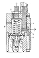
- Die Erfindung wird nachfolgend unter Bezugnahme auf die beiliegende Zeichnung beispielsweise erläutert. Die einzige Figur zeigt das Druckregelventil im Längsschnitt.
- Das Druckregelventil selbst arbeitet in bekannter Weise als P-Regler. Der Primärdruck tritt bei 1 ein. Durch Rechtsdrehen einer Einstellspindel 3 wird nun eine Einstellfeder 4 gespannt und eine Membrane 5 nach unten gedrückt. Dabei betätigt sie einen Ventilbetätigungsstift 6 und ein Ventilteller 7 hebt sich vom Ventilsitz 8 ab. Durch den entstehenden Ringspalt strömt nun die Druckluft in den Sekundärdruckraum 2 und gelangt am Ausgang 3 zum Verbraucher. Erfolgt keine Entnahme, so baut sich im Sekundärdruckraum 2 ebenfalls ein Druck auf und drückt die Membrane 5 wieder nach oben.
- Dadurch wird der Ventilteller 7 wieder auf seinen Sitz 8 gedrückt und das Ventil schliesst. Bei Luftentnahme sinkt der Druck im Sekundärdruckraum 2, die Federkraft überwiegt die Membrankraft und das Ventil öffnet wieder.
- Der Oeffnungsweg des Ventiltellers 7 ist nun proportional der Druckdifferenz dp zwischen dem eingestellten Sekundärdruck und dem tatsächlich im Sekundärdruckraum 2 herrschenden Druck. Dieser Sachverhalt wird nun erfindungsgemäss zur elektrischen Druckkontrolle ausgenützt.
- Die Einstellfeder 4 wirkt über einen Führungskolben 9 auf die Membrane 5. Der Führungskolben 9 und ein in diesen eingepresster Stift 10 machen also den gleichen von Δp abhängigen Weg wie die Membrane 5, der Ventilbetätigungsstift 6 sowie des Ventiltellers 7.
- Fällt nun der Sekundärdruck ab, so bewegt sich der Stift 10 nach unten, der Abstand a zwischen ihm und einem induktiven Näherungsschalter 11 vergrössert sich und der Näherungsschalter 11 gibt beim Ueberschreiten eines vorgewählten Δp-Grenzwertes bzw. Abstandes a ein elektrisches Signal ab. Dieser dp-Grenzwert verändert sich nicht beim Verstellen des Sekundärdruckes. Somit ist ohne Neueinstellung der elektrischen Druckkontrolle diese auch bei veränderter Sekundärdruckeinstellung gewährleistet. Mit 12 ist eine Einstellschraube bezeichnet, die verhindert, dass ein vorwählbarer Minimalsekundärdruck unterschritten werden kann.
Claims (4)
Applications Claiming Priority (2)
| Application Number | Priority Date | Filing Date | Title |
|---|---|---|---|
| CH51083A CH658503A5 (de) | 1983-01-28 | 1983-01-28 | Druckregelventil mit signalabgabe zwecks sekundaerdruckueberwachung. |
| CH510/83 | 1983-01-28 |
Publications (3)
| Publication Number | Publication Date |
|---|---|
| EP0117844A2 true EP0117844A2 (de) | 1984-09-05 |
| EP0117844A3 EP0117844A3 (en) | 1985-07-24 |
| EP0117844B1 EP0117844B1 (de) | 1988-06-15 |
Family
ID=4188658
Family Applications (1)
| Application Number | Title | Priority Date | Filing Date |
|---|---|---|---|
| EP19840810035 Expired EP0117844B1 (de) | 1983-01-28 | 1984-01-20 | Druckregelventil mit elektrischer Kontrolle |
Country Status (3)
| Country | Link |
|---|---|
| EP (1) | EP0117844B1 (de) |
| CH (1) | CH658503A5 (de) |
| DE (1) | DE3472150D1 (de) |
Cited By (1)
| Publication number | Priority date | Publication date | Assignee | Title |
|---|---|---|---|---|
| EP1031900A1 (de) * | 1999-02-22 | 2000-08-30 | Smc Corporation | Regler |
Families Citing this family (1)
| Publication number | Priority date | Publication date | Assignee | Title |
|---|---|---|---|---|
| DE29801695U1 (de) * | 1998-02-02 | 1998-05-20 | Klamert, Dieter, 87700 Memmingen | Heizkörper-Thermostatventil mit Durchflußanzeige |
Family Cites Families (8)
| Publication number | Priority date | Publication date | Assignee | Title |
|---|---|---|---|---|
| DE1640375B1 (de) * | 1967-03-31 | 1972-01-20 | Herion Werke Kg | Elektrischer Stroemungsschalter |
| US3898403A (en) * | 1969-02-03 | 1975-08-05 | Itt | Pressure sensitive control apparatus with magnet actuated switch and valve |
| DE2412054C3 (de) * | 1974-03-11 | 1978-12-21 | Aqua Butzke-Werke Ag, 1000 Berlin | Von der Durchflußmenge unabhängig arbeitende Differenzdruck-Schaltarmatur für flüssige oder gasförmige Medien |
| US3989911A (en) * | 1975-09-05 | 1976-11-02 | Perry Joseph A | Magnetic differential pressure switch |
| US4081621A (en) * | 1976-04-26 | 1978-03-28 | Carr-Griff, Inc. | Pressure switch with diaphragm and valve means |
| US4242082A (en) * | 1978-08-23 | 1980-12-30 | Robertshaw Controls Company | Fluid flow sensing switch device |
| US4317971A (en) * | 1980-05-27 | 1982-03-02 | Rk Industries | Adjustable pressure and vacuum limit switch valve |
| US4423751A (en) * | 1980-12-09 | 1984-01-03 | Cummins Engine Company, Inc. | Bypass valve and alarm assembly |
-
1983
- 1983-01-28 CH CH51083A patent/CH658503A5/de not_active IP Right Cessation
-
1984
- 1984-01-20 DE DE8484810035T patent/DE3472150D1/de not_active Expired
- 1984-01-20 EP EP19840810035 patent/EP0117844B1/de not_active Expired
Cited By (2)
| Publication number | Priority date | Publication date | Assignee | Title |
|---|---|---|---|---|
| EP1031900A1 (de) * | 1999-02-22 | 2000-08-30 | Smc Corporation | Regler |
| US6289925B1 (en) | 1999-02-22 | 2001-09-18 | Smc Corporation | Regulator |
Also Published As
| Publication number | Publication date |
|---|---|
| CH658503A5 (de) | 1986-11-14 |
| DE3472150D1 (en) | 1988-07-21 |
| EP0117844A3 (en) | 1985-07-24 |
| EP0117844B1 (de) | 1988-06-15 |
Similar Documents
| Publication | Publication Date | Title |
|---|---|---|
| EP0845397B1 (de) | Druckregelvorrichtung für elektropneumatische Bremsanlagen von Fahrzeugen, insbesondere Nutzfahrzeugen | |
| DE2748079C2 (de) | Wasserdruck-Verstärkungsanlage | |
| DE2657854A1 (de) | Gasdruckregler | |
| DE2453734C3 (de) | Versorgungsblock für ein Atemgerät mit einem Druckgasvorrat | |
| EP0093340A2 (de) | Elektropneumatisches Servoventil zur Steuerung eines Volumenstromes bzw. eines Druckes | |
| DE102018200487A1 (de) | Vorrichtung und Verfahren zur Realisierung kontrollierter Reaktionen bei einer Systemstörung | |
| EP0810136A1 (de) | Druckmittelanlage | |
| DE1802413A1 (de) | Stroemungsmittel-Steuereinrichtung | |
| EP0289712B1 (de) | Druckregelventil | |
| EP0117844A2 (de) | Druckregelventil mit elektrischer Kontrolle | |
| DE3233782C2 (de) | ||
| DE2041766A1 (de) | Druckregler | |
| CH641879A5 (de) | Vorrichtung zur signalwandlung. | |
| EP0100784A1 (de) | Druckbegrenzungsventil mit elektrisch einstellbarem Ansprechwert | |
| EP0206132B1 (de) | Druckabhängig gesteuerter Schalter | |
| AT404065B (de) | Startventil für pneumatische anlagen | |
| EP0215206A1 (de) | Elektropneumatische Führerbremsanlage für Schienenfahrzeuge | |
| EP0546488A2 (de) | Ventileinrichtung zur Verschleissoptimierung zwischen Bremsen von Nutzfahrzeugen | |
| DE3725635C2 (de) | ||
| AT233992B (de) | Druckregler mit Sicherheitsventil | |
| DE2449178A1 (de) | Zweileitungs-zweikreis-bremsanlage | |
| DE3521925A1 (de) | Einrichtung zur automatischen drucksteuerung von luftkissen | |
| DE8619382U1 (de) | Pneumatischer Druckregler für Kraftfahrzeug-Bremsanlagen | |
| DE3712481A1 (de) | Ventilanordnung mit sicherheitsfunktion | |
| DE4136560C2 (de) |
Legal Events
| Date | Code | Title | Description |
|---|---|---|---|
| PUAI | Public reference made under article 153(3) epc to a published international application that has entered the european phase |
Free format text: ORIGINAL CODE: 0009012 |
|
| AK | Designated contracting states |
Designated state(s): DE FR GB IT |
|
| PUAL | Search report despatched |
Free format text: ORIGINAL CODE: 0009013 |
|
| AK | Designated contracting states |
Designated state(s): DE FR GB IT |
|
| 17P | Request for examination filed |
Effective date: 19860116 |
|
| 17Q | First examination report despatched |
Effective date: 19861204 |
|
| GRAA | (expected) grant |
Free format text: ORIGINAL CODE: 0009210 |
|
| AK | Designated contracting states |
Kind code of ref document: B1 Designated state(s): DE FR GB IT |
|
| PG25 | Lapsed in a contracting state [announced via postgrant information from national office to epo] |
Ref country code: IT Free format text: LAPSE BECAUSE OF FAILURE TO SUBMIT A TRANSLATION OF THE DESCRIPTION OR TO PAY THE FEE WITHIN THE PRESCRIBED TIME-LIMIT;WARNING: LAPSES OF ITALIAN PATENTS WITH EFFECTIVE DATE BEFORE 2007 MAY HAVE OCCURRED AT ANY TIME BEFORE 2007. THE CORRECT EFFECTIVE DATE MAY BE DIFFERENT FROM THE ONE RECORDED. Effective date: 19880615 |
|
| REF | Corresponds to: |
Ref document number: 3472150 Country of ref document: DE Date of ref document: 19880721 |
|
| ET | Fr: translation filed | ||
| GBT | Gb: translation of ep patent filed (gb section 77(6)(a)/1977) | ||
| PLBE | No opposition filed within time limit |
Free format text: ORIGINAL CODE: 0009261 |
|
| STAA | Information on the status of an ep patent application or granted ep patent |
Free format text: STATUS: NO OPPOSITION FILED WITHIN TIME LIMIT |
|
| 26N | No opposition filed | ||
| ITTA | It: last paid annual fee | ||
| PGFP | Annual fee paid to national office [announced via postgrant information from national office to epo] |
Ref country code: FR Payment date: 19951207 Year of fee payment: 13 |
|
| PGFP | Annual fee paid to national office [announced via postgrant information from national office to epo] |
Ref country code: GB Payment date: 19951219 Year of fee payment: 13 |
|
| PGFP | Annual fee paid to national office [announced via postgrant information from national office to epo] |
Ref country code: DE Payment date: 19951220 Year of fee payment: 13 |
|
| PG25 | Lapsed in a contracting state [announced via postgrant information from national office to epo] |
Ref country code: GB Effective date: 19970120 |
|
| GBPC | Gb: european patent ceased through non-payment of renewal fee |
Effective date: 19970120 |
|
| PG25 | Lapsed in a contracting state [announced via postgrant information from national office to epo] |
Ref country code: FR Effective date: 19970930 |
|
| PG25 | Lapsed in a contracting state [announced via postgrant information from national office to epo] |
Ref country code: DE Effective date: 19971001 |
|
| REG | Reference to a national code |
Ref country code: FR Ref legal event code: ST |