EP0117805A1 - Modular heat exchanger and process for its manufacture - Google Patents
Modular heat exchanger and process for its manufacture Download PDFInfo
- Publication number
- EP0117805A1 EP0117805A1 EP84400301A EP84400301A EP0117805A1 EP 0117805 A1 EP0117805 A1 EP 0117805A1 EP 84400301 A EP84400301 A EP 84400301A EP 84400301 A EP84400301 A EP 84400301A EP 0117805 A1 EP0117805 A1 EP 0117805A1
- Authority
- EP
- European Patent Office
- Prior art keywords
- partitions
- series
- channels
- edges
- solid
- Prior art date
- Legal status (The legal status is an assumption and is not a legal conclusion. Google has not performed a legal analysis and makes no representation as to the accuracy of the status listed.)
- Granted
Links
Images


Classifications
-
- F—MECHANICAL ENGINEERING; LIGHTING; HEATING; WEAPONS; BLASTING
- F28—HEAT EXCHANGE IN GENERAL
- F28F—DETAILS OF HEAT-EXCHANGE AND HEAT-TRANSFER APPARATUS, OF GENERAL APPLICATION
- F28F21/00—Constructions of heat-exchange apparatus characterised by the selection of particular materials
- F28F21/06—Constructions of heat-exchange apparatus characterised by the selection of particular materials of plastics material
- F28F21/065—Constructions of heat-exchange apparatus characterised by the selection of particular materials of plastics material the heat-exchange apparatus employing plate-like or laminated conduits
-
- F—MECHANICAL ENGINEERING; LIGHTING; HEATING; WEAPONS; BLASTING
- F28—HEAT EXCHANGE IN GENERAL
- F28F—DETAILS OF HEAT-EXCHANGE AND HEAT-TRANSFER APPARATUS, OF GENERAL APPLICATION
- F28F3/00—Plate-like or laminated elements; Assemblies of plate-like or laminated elements
- F28F3/08—Elements constructed for building-up into stacks, e.g. capable of being taken apart for cleaning
- F28F3/086—Elements constructed for building-up into stacks, e.g. capable of being taken apart for cleaning having one or more openings therein forming tubular heat-exchange passages
-
- Y—GENERAL TAGGING OF NEW TECHNOLOGICAL DEVELOPMENTS; GENERAL TAGGING OF CROSS-SECTIONAL TECHNOLOGIES SPANNING OVER SEVERAL SECTIONS OF THE IPC; TECHNICAL SUBJECTS COVERED BY FORMER USPC CROSS-REFERENCE ART COLLECTIONS [XRACs] AND DIGESTS
- Y10—TECHNICAL SUBJECTS COVERED BY FORMER USPC
- Y10T—TECHNICAL SUBJECTS COVERED BY FORMER US CLASSIFICATION
- Y10T29/00—Metal working
- Y10T29/49—Method of mechanical manufacture
- Y10T29/4935—Heat exchanger or boiler making
Definitions
- the invention relates to a heat exchange device of modular structure, intended more particularly for carrying out a heat exchange between several fluids, in particular between two gases.
- Tubular and shell-and-tube heat exchangers are known.
- one of the fluids participating in the exchange passes through the tubes, the other fluid passes around the tubes in the shell.
- the exchange surface per unit volume known as the specific surface, which it is possible to obtain by means of such exchangers, is generally limited due to the fact that, for production reasons, it is difficult to reduce the diameter of the tubes and the spacing between tubes below a value of the order of 1 cm.
- Plate heat exchangers make it possible to obtain larger specific exchange surfaces.
- the fluids participating in the exchange circulate on either side of the different plates but the specific surface is also limited by the need not to reduce the spacing between plates too much.
- heat exchangers consisting of stacks of perforated sheets, juxtaposed so as to obtain, by superposition of the perforations, channels some of which can be traversed by a relatively hot fluid, others by a relatively cold fluid, the transfer thermal between the channels being provided by conduction through the material forming at least part of said sheets.
- Heat exchangers are most often made of metallic materials. In cases where condensation occurs during heat exchange, such as in the case of heat recovery from fumes from a heating boiler, these materials have the disadvantage of being easily corroded.
- a modular structure heat exchange device comprising at least one area of modular structure essentially consisting of a stack of trellises built one above the other so contiguous and each formed by an intertwining of two series of lamellae joined together in a joined manner by mutual engagement of the lamellae, parallel to each other, of the first series and of the lamellae, parallel to each other, of the second series, at the level of recesses on one of the edges (for example upper) of the lamellae of the first series and on the opposite edge (for example lower) of the lamellae of the second series, said stack creating spaces for the circulation of at least two fluids in relation to heat exchange.
- the modular structure of the exchange zone could also essentially consist of a stack of intersecting series of lamellae, joined together by mutual engagement of the lamellae, parallel to each other, in a series with the lamellae, parallel to each other, of the consecutive series, at the level of notches formed on the two edges of each lamella, facing each other; said stacking of series of strips creating spaces for the circulation of at least two fluids in heat exchange relation.
- the device thus described produced by a simple assembly of elements, allowed easy adaptation to the geometric requirements encountered by the user, in particular facilitating its insertion into existing systems.
- the possibility of making this device using a wide variety of materials also makes it easy to adapt it to the nature of the fluids involved in the heat exchange, in particular in cases where corrosion is to be feared, for example in exchanges thermal with condensation.
- the device thus described also had a high specific heat exchange surface.
- a heat exchange device comprises a zone in which at least two fluids in heat exchange relation circulate and means for the supply and departure of said fluids, this zone of modular structure being essentially constituted by a stack of lattices joined together and each made up of two series of intersecting partitions, this stack creating spaces for the circulation of said fluids, each lattice constituting a module being further formed in one piece and designed in such a way that, on each of its faces, the edges of the partitions of one of the two series are, over at least part of their length, projecting from the plane formed by the edges, at least partially set back, partitions of the other series, the stacking of the trellis being carried out by bringing opposite the projecting edges of a series of partitions on one of the faces of any lattice of the stack with the recessed edges of the corresponding series of partitions on the opposite face of the adjacent lattice, the height of emergence of said projecting edges and the depth of depression of said recessed edges facing each other in the
- Each trellis is advantageously produced by molding a solidifiable material and in particular using an injection molding process, in particular if the material used for the manufacture of the trellis is a light alloy or a thermoplastic material, or by simple mold casting if this material is thermosetting.
- the term "lattice” designates a grid, formed by an interweaving of solid partitions of a first series, parallel to each other, with partitions of a second solid or perforated series, parallel to each other. If we consider the trellis (or grid) in a horizontal position, the two series of partitions are placed in two series of vertical planes parallel to each other, each plane of one of the two series intersecting the planes of the other series according to dihedral angles of vertical edge, equal to each other. These dihedral angles are preferably 90 °.
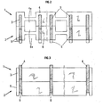
- the first embodiment of a structure according to the invention illustrated by FIGS. 1, 2, 3 and 4A to 4D can correspond to an exchange zone in which two fluids can circulate in crossed currents.
- a trellis of the first type 1 comprises two series of interwoven partitions sées comprising a series of solid partitions 3 and a series of perforated partitions 4, for example of the same height, which are arranged at two different levels.
- the openwork partitions 4 have recesses or notches 4A which can have any shape; they can be circular, square, rectangular, etc ... they can lead, or not, on one of the edges of the partition. They can also consist of several disjointed recesses on each partition, one or more of which may or may not lead to one edge or to both edges of the partition.
- FIG. 1 Also shown in FIG. 1 is a trellis of a second type 2, also comprising two series of intersecting partitions comprising a series of solid partitions 5 and a series of perforated partitions 6, for example of the same height, which are arranged at two different levels, these partitions 5 and 6 having the same thickness and the same spacing as the partitions 3 and 4 respectively.
- the partitions 3 of a first type trellis are adapted to be embedded at their lower part in notches formed by the partitions 6 of a type 2 trellis whose partitions 5 form at their lower part notches receiving the partitions 4 a second type 1 trellis.
- the recesses or notches 6A of the perforated partitions 6 of the trellis 2 can have various shapes and arrangements (FIG. 2).
- the heat exchange structure according to the invention is formed by an alternating stack of type 1 and type 2 trellises, the underside of each type 1 trellis fitting in (as it appears in FIG. 1) on the upper face of a type 2 trellis. Likewise, the lower face of each type 2 trellis must be able to be embedded on the upper face of a type 1 trellis, not shown in FIG. 1.
- FIG. 1 only shows two lattices, each of which has only a small number of partitions, but it is understood that a stack of lattices constituting a heat exchange zone according to the invention may consist of a large number of superimposed trellises from ten to several hundred and that each trellis may include a large number of intersecting partitions (from ten to several hundred).
- the depression of the hollow (lower) edges of the series of partitions 6 of the trellis 2 is made to correspond to the emergence of the (upper) protruding edges of the series of partitions 4 of a type 1 trellis located below the type 2 trellis.
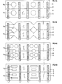
- Figure 2 corresponds to a section through a plane II parallel to the partitions 4 and 6 of the two trellis of Figure 1 in their assembly position and similarly Figure 3 corresponds to a section through a plane III parallel to the partitions 3 and 5 of the two trellis of Figure 1 in their assembly position.
- FIGS. 4A to 4D correspond to sections similar to that of FIG. 2, but for other forms of the recesses 4A, 6A of the partitions 4 and 6.
- the different stacked trellises fit into one another and, in this embedding, the protruding (or recessed) parts of one of the faces of a trellis of the first type come into contact with the homologous recessed (or projecting) parts of the opposite face of the second type of trellis.
- the partitions described above therefore determine two kinds of spaces for the circulation of fluids which it is desired to put in heat exchange relationship. Indeed, all the solid walls, formed by the superimposition of solid partitions, and parallel to each other, separate spaces which, in relation to the whole of the exchange structure (the lattice stack), appear as slices. Due to the alternation of solid panels and perforated panels on the walls formed by superposition of the perforated partitions, the sections defined above are, alternately, of two different types. Some are subdivided into channels, of rectangular or square section for example, separated by solid panels; the other sections are not subdivided into separate channels, owing to the fact that the openings in the openwork sections constitute as many passages from one channel to the neighboring channel.
- the separate channels delimited in the various spaces (or sections) are generally traversed by a first fluid participating in the heat exchange.
- the fluid then circulates in a direction parallel to the planes of the solid partitions constituting the exchange zone.
- a second fluid is circulated in the spaces (or sections) not subdivided into separate channels.
- the fluid can pass through each of these sections right through using the communication passages formed by the recesses it meets, the remains of the solid parts surrounding the recesses constituting fins or baffles.
- the fluid circulates in an overall direction substantially perpendicular to the openwork partitions and parallel to the solid partitions. Under these conditions, the two fluids circulate in crossed currents.
- the ends of the spaces (or sections) traversed by the second fluid situated on the faces of the stack intended for the entry and exit of the first fluid are closed for example by end plates (such as 11 and 12, FIG. 1 ) coming to fit on the first (and the last) lattice of the stack, these plates covering one space out of two, the spaces remaining open corresponding to the entry (or exit) of said first fluid.
- the openings of the sections traversed by the second fluid on the faces of the stack intended for the entry and exit of said second fluid are made de facto by the recesses in the perforated partitions constituting said faces.
- the heat exchanger structure as described above can constitute the exchange body of an exchanger intended for the circulation of the two fluids in cross currents, one of the fluids, for example fumes , traversing the separate channels from top to bottom or from bottom to top and the other fluid, for example air to be heated, then circulating from a side face to the opposite face.
- the means for supplying and leaving the fluids may consist of conventional means, in particular cylindrical conduits which are suitably connected to the faces of the exchange body through which must enter (or exit) each of the fluids concerned. These means have not been illustrated in FIG. 1.
- a second embodiment of the first heat exchange structure according to the invention described above can consist essentially, like the first mode described, in a stack of lattices (or grids) built in one above the other, and formed each of two series of intersecting partitions.
- the two series of intersecting partitions each forming trellises are both made of solid partitions.
- the description of this second embodiment will therefore be similar to that of the first, provided that the "perforated" partitions are replaced by "solid" partitions.
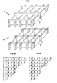
- FIGS. 6A and 6B show possible arrangements for the channels traversed by the two fluids.
- the structure considered is constituted by alternating stacking of any number of trellises such as 13 and 14.
- the embedding of these trellises is carried out in the same manner as for the first embodiment described: the projecting parts are made to correspond (or recessed) of a trellis, for example of the first type (such as 13) with the recessed (or protruding) parts of a trellis of the second type (such as 14) located below or above said trellis of the first type.
- the spaces will no longer be distinguished (or sections) divided into separate channels and the spaces (or sections) not subdivided into separate channels but comprising passageways that are the recesses of the perforated partitions.
- the stack of trellises consisting only of solid partitions will only comprise channels, all separated from each other by solid partitions resulting from the superposition of the solid parts of the homologous partitions.
- This structure can constitute the body of a heat exchanger in which for example two fluids circulate in parallel currents (in co-currents or against the current).
- each channel A traversed by one of the two fluids is contiguous with at least two channels B traversed by the other fluid. Examples of such distributions are given in Figures 6A and 6B.
- a particularly advantageous aspect of the invention consists in opening the exchange zone 1.a each of its ends on designed fluid inlet and outlet heads each analogously to the first embodiment described above (cross-flow circulation).
- FIG. 7 shows in perspective a heat exchanger formed of a central body and two collectors at its ends; and FIGS. 8A, 8B and 8C schematically show several possible relative arrangements for the central body and the two manifolds.
- the heat exchange device 15 comprises a central body 16 and two collectors 17 and 18.
- the central body 16 is in the form of a parallelepiped with a rectangular or square base formed, by the stacking of the trellis which constitute it, of a determined number of rows of section channels in parallelogram trusses (for example rhombus, rectangle 'or square), each row comprising a determined number of channels.
- the collectors 17 and 18 each consist of a stack of several lattices similar to those of FIG. 1, which include solid partitions and intersecting perforated partitions.
- the openwork partitions have recesses provided. alternately every second time in the parts of said partitions of the second series comprised between two notches of the first series with which they form a dihedral angle.
- a second fluid can, for example, be brought in the direction of the arrows 19, through the recesses of the perforated partitions flush with the face considered, in spaces (or sections) passing through the manifold 17. These spaces are closed on the upper face 23 of the manifold 17 by plates such as 11 (in FIG.
- the spaces traversed by said second fluid are also closed off on the face of the manifold 17 opposite to the inlet face, by substitution of a solid partition for the extreme perforated partitions of each of the trellises whose stack constitutes said manifold 17, the superposition of these solid partitions constituting a continuous wall 25 (not visible in Figure 7).
- the spaces traversed by said second fluid are, at the junction of the manifold 17 with the central body 16, in communication with the corresponding rows of channels, the plates such as 12 (shown in Figure 1) being, in this case, of course omitted.
- the rows of channels of the manifold 17, through which the second fluid exits are in communication with the rows of homologous channels of the central body 16.
- the manifold 18 located for example at the bottom of the central body 16 can be described in a similar manner.
- the second fluid exits for example in the direction of the arrows 20, through the recesses of the perforated partitions flush with the face in question, outside the spaces (or sections) passing through the manifold 18 and separated from each other by rows of channels through which between the first fluid in the direction of the arrows 21.
- Said spaces (or sections) are closed on the lower face 24 of the collector 18 by plates similar to the plates 12 (FIG. 1), which fit on the lower lattice of the collector 18 , the spaces remaining open on this face corresponding to the rows of channels through which between said first fluid.
- the spaces traversed by said second fluid are also closed on the face of the manifold 18 opposite to the outlet face, by substitution of a solid partition for the extreme perforated partition of each of the trellises whose stack constitutes the manifold 18, the superposition of these solid partitions constituting a continuous wall 26.
- the spaces traversed by said second fluid are, at the junction of the manifold 18 with the central body 16, in communication with the corresponding rows of channels, the plates such as 11 (shown in FIG. 1) being, in the present case, of course omitted.
- the rows of channels of the manifold 18, through which the first fluid enters are in communication with the rows of homologous channels of the central body 16.
- the exchangers can be associated in series so as to lengthen the path followed by one of the fluids or by the two fluids.
- the heat exchange zone of the device is essentially constituted by the stack of identical lattices, corresponding, from the point of view of their overall geometry, to the superposition of two lattices of different types such as 'They have been defined in the foregoing description.
- lattices of a unique type, made up of an interweaving of partitions are such that the upper edges of the partitions of one of the series protrude from the upper face of the lattice and the upper edges of these same partitions are recessed on the face inferior of the trellis, it being understood moreover that the emergence of the upper edges (projecting) of the partitions of the first series with respect to the upper edges of the partitions of the second series is equal to the sinking of the lower edges (recessed) of the same partitions of the first series with respect to the lower edges of the partitions of the second series.
- partitions of one of the series are full and those of the other series can be full (circulation of fluids with parallel current) or openwork for example every other section (circulation of fluids with crossed current).
- Figures 2, 3 and 4 A to 4 D can represent this embodiment of the device of the invention (in the version corresponding to an exchange between fluids circulating at cross currents), if we consider that each figure is a view no more of the superposition of two lattices of different types but of a single lattice. In this perspective, it is advisable to disregard the solutions of continuity (horizontal lines) between the upper part and the lower part of the trellis thus represented.
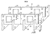
- a second heat exchange structure according to the invention is produced by stacking identical lattices formed by interlacing solid partitions 27 of a first series, parallel to each other, with partitions 28 of a second series, solid or perforated, parallel between them.
- FIG. 9 shows in perspective an example of such a type of trellis and FIGS. 9A and 9B show in section along planes A and B respectively the partitions of two trellis of the same type in the assembly position.
- This second heat exchange structure consists of a stack of lattices made up of interlocking partitions, assembled one above the other by mutual straddling of each partition of a first series (such as 27, FIG. 9) of a lattice by the partitions of a second series (such as 28, FIG. 9) of another lattice.
- the partitions of the two series of each lattice have on their edges located in the planes of the external faces of the lattice notches (respectively 30 and 31), intended, one (the notches30 of the lower edge of the partitions which are parallel to each other from the first series ), to ensure the assembly by mutual straddling with the notches 31 of the upper edge of the partitions which are parallel to each other of the second series of the trellis below, the others (the upper notches 31) intended to assemble the trellis by mutual straddling with the notches 30 of the lower edge of the partitions of the trellis located above.
- the planes of the partitions of the first series intersect the planes of the partitions of the second series, at their respective notches, by forming dihedral angles of vertical edge (if we consider a stack in which the partitions are in planes vertical), these dihedral angles equal to each other are preferably 90 ° (the intersection of the series of partitions is done at right angles).
- the notches on the same edge of the partitions of the first series have the same depth and the same width, said width being equal to or substantially equal to the thickness of the partitions of the second series.
- the partitions of the first series (such as 27) and the partitions of the second series (such as 28) all have the same height h.
- Any number of trellises can be assembled one above the other, ranging, for example, from a few tens to several hundred.
- the partitions of the first series are so-called “full” partitions, that is to say comprising only the notches necessary for their assembly with the partitions of the second series of the trellis located immediately above or below.
- the partitions of the second series can be "full”, like the partitions 27 above of the first series, or “perforated”, that is to say comprising recesses arranged alternately in one in two solid parts delimited by two consecutive partitions of the first series with which they form a dihedral angle.
- the heat exchange structure produced by the assembly of the various trellises consists only of vertical tubular channels, of section in the shape of a parallelogram (for example rhombus, rectangle, or square) , as already described above in relation to FIG. 5.
- These channels can be supplied by the fluids participating in the exchange according to the distribution shown in FIG. 6A or 6B, the circulation of the two fluids can be done in co-current or against a current.
- the structure produced comprises rows of separate channels, alternating with spaces (or sections) in which the different channels of the same row communicating with one another through the recesses made in the so-called “openwork partitions” ".
- Such a structure equivalent to that shown in Figure 1, allows for heat exchanges between fluids flowing at cross currents.
- the trellis constituting the different heat exchange structures according to the invention can be made of various good or medium heat conducting materials, depending on the temperatures of the fluids involved in the heat exchange.
- the material may consist of a thermoplastic material such as polypropylene, optionally charged, for temperatures below 100 ° C, polyvinylidene fluoride, for temperatures ranging for example from 100 to 140 ° C, or an ethylene-tetra copolymer -fluoroethylene charged, for temperatures ranging, for example, from 140 to 190 ° C.
- a thermoplastic material such as polypropylene, optionally charged, for temperatures below 100 ° C, polyvinylidene fluoride, for temperatures ranging for example from 100 to 140 ° C, or an ethylene-tetra copolymer -fluoroethylene charged, for temperatures ranging, for example, from 140 to 190 ° C.
- the mesh may also be made of thermosetting plastics, such as, for example, polyesters or epoxy resins.
- the material can also consist of a metal, a metal alloy, glass, cement or ceramic. It can also consist of a composite material such as, for example, a plastic material loaded with pulverulent, granular, filamentary, woven or nonwoven products, said products or fillers themselves being able to consist of metals, alloys, amorphous carbon, graphite, glass, ceramic or mineral salts.
- An advantageous embodiment of the trellis can consist of a molding or injection operation of the chosen material, in particular when said material is a light alloy or a thermoplastic or thermosetting material.
- the trellises can be assembled by simple mechanical embedding of their partitions; they can also be consolidated or made more watertight by soldering, tinning, welding or gluing.
- the dimensions of the devices of the invention can be very varied: the partitions can have a length of a few hundred meters to several meters and a height of a few millimeters to several centimeters, for example. It is possible to use for each series a variable number of partitions, for example from ten to several hundred, and to stack a variable number of trellis also from ten to several hundred.
- the exchange surface per unit volume of the devices according to the invention can be high. Average values of this surface are in the neighborhood of 150 to 20 0 m 2 per m 3 .
- its mass surface can be around 6 to 7 dm 2 / kg for steel and around 40 to 50 dm 2 / kg for a plastic material. .
Abstract
On décrit un dispositif d'échange thermique qui comporte une zone dans laquelle circulent au moins deux fluides en relation d'échange thermique et des moyens pour l'amenée et le départ desdits fluides, cette zone de structure modulaire étant essentiellement constituée par un empilement de treillis (1, 2) assemblés de façon jointive et constitués, chacun, de deux séries de cloisons entrecroisées (5, 6), cet empilement créant des espaces pour la circulation desdits fluides, chaque treillis (1, 2) constituant un module étant en outre formé d'une seule pièce et conçu de telle manière que, sur chacune de ses faces, les bords des cloisons (5, 6) d'une des deux séries sont, sur au moins une partie de leur longueur en saillie par rapport au plan formé par les bords, au moins en partie en retrait, des cloisons (5, 6) de l'autre série, l'empilement des treillis (1, 2) étant réalisé en amenant en regard les bords en saillie d'une série de cloisons sur une des faces d'un treillis quelconque de l'empilement avec les bords en retrait de la série correspondante de cloisons sur la face opposée du treillis adjacent, la hauteur d'émergence desdits bords en saillie et la profondeur adjacent, la hauteur d'émergence desdits bords en saillie et la profondeur d'enfoncement desdits bords en retrait venant en regard dans l'empilement des treillis (1, 2), étant égales entre elles.A heat exchange device is described which comprises a zone in which at least two fluids circulating in heat exchange relation and means for the supply and departure of said fluids, this zone of modular structure being essentially constituted by a stack of trellis (1, 2) joined together and made up, each, of two series of intersecting partitions (5, 6), this stack creating spaces for the circulation of said fluids, each trellis (1, 2) constituting a module being in additionally formed in one piece and designed in such a way that, on each of its faces, the edges of the partitions (5, 6) of one of the two series are, over at least part of their length projecting from the plane formed by the edges, at least partially set back, of the partitions (5, 6) of the other series, the stacking of the trellises (1, 2) being produced by bringing the projecting edges of a series opposite partitions on one side of any lattice of the th stacking with the recessed edges of the corresponding series of partitions on the opposite face of the adjacent lattice, the height of emergence of said protruding edges and the adjacent depth, the height of emergence of said protruding edges and the depth of depression of said recessed edges facing each other in the stack of lattices (1, 2), being equal to each other.
Description
L'invention concerne un dispositif d'échange de chaleur de structure modulaire, destiné plus particulièrement à réaliser un échange thermique entre plusieurs fluides, notamment entre deux gaz.The invention relates to a heat exchange device of modular structure, intended more particularly for carrying out a heat exchange between several fluids, in particular between two gases.
On connaît les échangeurs de chaleur à tubes et à calandre. Dans ceux-ci, l'un des fluides participant à l'échange passe dans les tubes, l'autre fluide passe autour des tubes dans la calandre. La surface d'échange par unité de volume, dite surface spécifique, qu'il est possible d'obtenir au moyen de tels échangeurs est généralement limitée du fait que, pour des raisons de réalisation, il est difficile de réduire le diamètre des tubes et l'écartement entre tubes au-dessous d'une valeur de l'ordre de 1 cm.Tubular and shell-and-tube heat exchangers are known. In these, one of the fluids participating in the exchange passes through the tubes, the other fluid passes around the tubes in the shell. The exchange surface per unit volume, known as the specific surface, which it is possible to obtain by means of such exchangers, is generally limited due to the fact that, for production reasons, it is difficult to reduce the diameter of the tubes and the spacing between tubes below a value of the order of 1 cm.
Les échangeurs à plaques permettent d'obtenir des surfaces spécifiques d'échange plus importantes. Dans ces échangeurs, les fluides participant à l'échange circulent de part et d'autre des différentes plaques mais la surface spécifique est également limitée par la nécessité de ne pas trop réduire l'écartement entre plaques.Plate heat exchangers make it possible to obtain larger specific exchange surfaces. In these exchangers, the fluids participating in the exchange circulate on either side of the different plates but the specific surface is also limited by the need not to reduce the spacing between plates too much.
On connaît encore des échangeurs de chaleur constitués d'empilements de feuilles perforées, juxtaposées de manière à obtenir, par superposition des perforations, des canaux dont certains peuvent être parcourus par un fluide relativement chaud, d'autres par un fluide relativement froid, le transfert thermique entre les canaux étant assuré par conduction à travers le matériau formant au moins une partie desdites feuilles.There are also known heat exchangers consisting of stacks of perforated sheets, juxtaposed so as to obtain, by superposition of the perforations, channels some of which can be traversed by a relatively hot fluid, others by a relatively cold fluid, the transfer thermal between the channels being provided by conduction through the material forming at least part of said sheets.
Les échangeurs de chaleur sont le plus souvent constitués de matériaux métalliques. Dans les cas où une condensation intervient lors de l'échange thermique, comme par exemple dans le cas de la récupération de chaleur sur fumées de chaudière de chauffage, ces matériaux présentent l'inconvénient d'être facilement corrodés.Heat exchangers are most often made of metallic materials. In cases where condensation occurs during heat exchange, such as in the case of heat recovery from fumes from a heating boiler, these materials have the disadvantage of being easily corroded.
Dans une demande de brevet déposée antérieurement, l'organisme demandeur a déjà décrit un dispositif d'échange thermique à structure modulaire comportant au moins une zone de structure modulaire essentiellement constituée d'un empilement de treillis encastrables les uns au-dessus des autres de façon jointive et formés chacun d'un entrecroisement de deux séries de lamelles assemblées de façon jointive par enfourchement mutuel des lamelles, parallèles entre elles, de la première série et des lamelles, parallèles entre elles, de la seconde série, au niveau d'échancrures ménagées sur un des bords (par exemple supérieur) des lamelles de la première série et sur le bord opposé (par exemple inférieur) des lamelles de la seconde série, ledit empilement créant des espaces pour la circulation d'au moins deux fluides en relation d'échange thermique.In a previously filed patent application, the applicant organization has already described a modular structure heat exchange device comprising at least one area of modular structure essentially consisting of a stack of trellises built one above the other so contiguous and each formed by an intertwining of two series of lamellae joined together in a joined manner by mutual engagement of the lamellae, parallel to each other, of the first series and of the lamellae, parallel to each other, of the second series, at the level of recesses on one of the edges (for example upper) of the lamellae of the first series and on the opposite edge (for example lower) of the lamellae of the second series, said stack creating spaces for the circulation of at least two fluids in relation to heat exchange.
Du fait du mode d'assemblage des lamelles, la zone d'échange était constituée plus particulièrement de l'empilement alterné de treillis de deux types différents :
- - les treillis du premier type étaient tels que les bords inférieurs des lamelles de la première série et les bords supérieurs des lamelles de la seconde série soient en saillie sur les faces correspondantes desdits treillis ; et
- - les treillis du second type étaient tels que les bords supérieurs des lamelles de la première série et les bords inférieurs des lamelles de la seconde série soient en retrait sur les faces correspondantes desdits treittis ;
- - en outre, l'émergence des bords inférieurs (en saillie) des lamelles de la première série des treillis du premier type était égale à l'enfoncement des bords supérieurs (en retrait) des lamelles de la première série des treillis du second type ; et
- - l'émergence des bords supérieurs (en saillie) des lamelles de la seconde série des treillis du premier type était égale à l'enfoncement des bords inférieurs (en retrait) des lamelles de la seconde série des treillis du second type.
- the trellises of the first type were such that the lower edges of the lamellae of the first series and the upper edges of the lamellae of the second series project from the corresponding faces of said trellis; and
- the trellises of the second type were such that the upper edges of the lamellae of the first series and the lower edges of the lamellae of the second series are set back on the corresponding faces of the said lattices;
- - In addition, the emergence of the lower edges (projecting) of the lamellae of the first series of trellises of the first type was equal to the sinking of the upper edges (recessed) of the lamellae of the first series of trellises of the second type; and
- - the emergence of the upper edges (protruding) of the lamellae of the second series of lattices of the first type was equal to the sinking lower edges (recessed) of the lamellae of the second series of trellises of the second type.
Dans cette demande de brevet, la zone d'échange à structure modulaire pouvait aussi être essentiellement constituée d'un empilement de séries entrecroisées de lamelles, assemblées de façon jointive par enfourchement mutuel des lamelles, parallèles.entre elles, d'une série avec les lamelles, parallèles entre elles, de la série consécutive, au niveau d'échancrures ménagées sur les deux bords de chaque lamelle, en regard les unes des autres ; ledit empilement de séries de lamelles créant des espaces pour la circulation d'au moins deux fluides en relation d'échange thermique.In this patent application, the modular structure of the exchange zone could also essentially consist of a stack of intersecting series of lamellae, joined together by mutual engagement of the lamellae, parallel to each other, in a series with the lamellae, parallel to each other, of the consecutive series, at the level of notches formed on the two edges of each lamella, facing each other; said stacking of series of strips creating spaces for the circulation of at least two fluids in heat exchange relation.
Le dispositif ainsi décrit, réalisé par un assemblage simple d'éléments, permettait une adaptation aisée aux impératifs géométriques rencontrés par l'utilisateur, en facilitant notamment son insertion dans des systèmes existants. La possibilité de réaliser ce dispositif à l'aide de matériaux très variés permet aussi de l'adapter facilement à la nature des fluides impliqués dans l'échange thermique, en particulier dans les cas où une corrosion est à craindre, par exemple dans les échanges thermiques avec condensation.The device thus described, produced by a simple assembly of elements, allowed easy adaptation to the geometric requirements encountered by the user, in particular facilitating its insertion into existing systems. The possibility of making this device using a wide variety of materials also makes it easy to adapt it to the nature of the fluids involved in the heat exchange, in particular in cases where corrosion is to be feared, for example in exchanges thermal with condensation.
Le dispositif ainsi décrit présentait en outre une surface spécifique d'échange thermique élevée.The device thus described also had a high specific heat exchange surface.
/servir à Les structures d'échange thermique de la demande antérieure pouvaient/ réaliser aussi bien des corps d'échangeurs à deux fluides circulant en courants parallèles (co-courant ou contre-courant) ou en courants croi- sés, que les têtes pour l'amenée et le départ des fluides./ used for the heat transfer structures of the earlier application could / achieve both exchanger bodies two fluids flowing in parallel-flow (co-current or against the current) or current croi- s ed, the heads for the supply and departure of fluids.
On a maintenant découvert qu'il était possible de réaliser des dispositifs d'échange thermique à structure modulaire plus simples, dont la fabrication et l'assemblage sont plus aisés à réaliser, notamment par des opérations automatisées.We have now discovered that it was possible to produce heat exchange devices with a simpler modular structure, the manufacture and assembly of which are easier to carry out, in particular by automated operations.
D'une manière générale, un dispositif d'échange thermique selon l'invention comporte une zone dans laquelle circulent au moins deux fluides en relation d'échange thermique et des moyens pour l'amenée et le départ desdits fluides, cette zone de structure modulaire étant essentiellement constituée par un empilement de treillis assemblés de façon jointive et constitués chacun, de deux séries de cloisons entrecroisées, cet empilement créant des espaces pour la circulation desdits fluides, chaque treillis constituant un module étant en outre formé d'une seule pièce et conçu de telle manière que, sur chacun de ses faces, les bords des cloisons d'une des deux séries sont, sur au moins une partie de leur longueur, en saillie par rapport au plan formé par les bords, au moins en partie en retrait, des cloisons de l'autre série, l'empilement des treillis étant réalisé en amenant en regard les bords en saillie d'une série de cloisons sur une des faces d'un treillis quelconque de l'empilement avec les bords en retrait de la série correspondante de cloisons sur la face opposée du treillis adjacent, la hauteur d'émergence desdits bords en saillie et la profondeur d'enfoncement desdits bords en retrait venant en regard dans l'empilement des treillis, étant égales entre elles.In general, a heat exchange device according to the invention comprises a zone in which at least two fluids in heat exchange relation circulate and means for the supply and departure of said fluids, this zone of modular structure being essentially constituted by a stack of lattices joined together and each made up of two series of intersecting partitions, this stack creating spaces for the circulation of said fluids, each lattice constituting a module being further formed in one piece and designed in such a way that, on each of its faces, the edges of the partitions of one of the two series are, over at least part of their length, projecting from the plane formed by the edges, at least partially set back, partitions of the other series, the stacking of the trellis being carried out by bringing opposite the projecting edges of a series of partitions on one of the faces of any lattice of the stack with the recessed edges of the corresponding series of partitions on the opposite face of the adjacent lattice, the height of emergence of said projecting edges and the depth of depression of said recessed edges facing each other in the stack of lattices, being equal between they.
Chaque treillis est avantageusement réalisé par moulage d'un matériau solidifiable et en particulier en utilisant un procédé de moulage par injection, notamment si le matériau utilisé pour la fabrication des treillis est un alliage léger ou un matériau thermoplastique, ou par simple coulée en moule si ce matériau est thermodurcissable.Each trellis is advantageously produced by molding a solidifiable material and in particular using an injection molding process, in particular if the material used for the manufacture of the trellis is a light alloy or a thermoplastic material, or by simple mold casting if this material is thermosetting.
Dans la présente description, le terme de "treillis" désigne une grille, formée d'un entrecroisement de cloisons pleines d'une première série, parallèles entre elles, avec des cloisons d'une seconde série pleines ou ajourées, parallèles entre elles. Si l'on considère le treillis (ou grille) en position horizontale, les deux séries de cloisons se placent dans deux séries de plans verticaux parallèles entre eux, chaque plan de l'une des deux séries coupant les plans de l'autre série selon des angles dièdres d'arête verticale, égaux entre eux. Ces angles dièdres sont de préférence de 90°.In the present description, the term "lattice" designates a grid, formed by an interweaving of solid partitions of a first series, parallel to each other, with partitions of a second solid or perforated series, parallel to each other. If we consider the trellis (or grid) in a horizontal position, the two series of partitions are placed in two series of vertical planes parallel to each other, each plane of one of the two series intersecting the planes of the other series according to dihedral angles of vertical edge, equal to each other. These dihedral angles are preferably 90 °.
Pour réaliser l'encastrement des divers treillis les uns sur les autres, on met en jeu selon l'invention, l'empilage alterné de treillis de deux types différents ou l'empilage de treillis semblables qui seront décrits dans la suite.To embed the various lattices on top of each other, the alternating stack of lattices of two different types or the stack of similar lattices which will be described below is brought into play according to the invention.
Des exemples de réalisation de l'invention sont illustrés par les figures annexées où :
- - la figure 1 montre en perspective avant leur assemblage deux treillis de types différents correspondant à un premier mode de réalisation,
- -
lesfigures 2 et 3 montrent les cloisons de ces deux treillis en position d'assemblage en coupe selon le plan II et selon le plan III respectivement représentés sur la figure 1, - - les figures 4A à 4D sont des vues correspondant à la figure 2 illustrant des cloisons ajourées par des évidements de différentes formes, à titre d'exemples,
- - la figure 5 montre avant leur assemblage deux treillis de types différents correspondant à un second mode de réalisation,
- - les figures 6A et 6B montrent des dispositions possibles pour les canaux parcourus par les deux fluides,
- - la figure 7 et les figures 8A, 8B, 8C montrent la réalisation d'un échangeur de chaleur formé d'un module central et de deux collecteurs à ses extrémités,
- - la figure 9 montre une autre structure de treillis d'échange thermique réalisée selon l'invention et,
- - les figures 9A et 9B montrent,en coupe selon les plans A et B respectivement,les cloisons de deux treillis du même type.en position d'assemblage .
- FIG. 1 shows in perspective before their assembly two lattices of different types corresponding to a first embodiment,
- FIGS. 2 and 3 show the partitions of these two trellises in the assembly position in section along plane II and along plane III respectively represented in FIG. 1,
- FIGS. 4A to 4D are views corresponding to FIG. 2 illustrating openwork partitions by recesses of different shapes, by way of examples,
- FIG. 5 shows before their assembly two lattices of different types corresponding to a second embodiment,
- FIGS. 6A and 6B show possible arrangements for the channels traversed by the two fluids,
- FIG. 7 and FIGS. 8A, 8B, 8C show the production of a heat exchanger formed by a central module and by two collectors at its ends,
- FIG. 9 shows another structure of heat exchange lattice produced according to the invention and,
- - Figures 9A and 9B show, in section along planes A and B respectively, the partitions of two trellises of the same type. in the assembled position.
Le premier mode de réalisation d'une structure selon l'invention,illustré par les figures 1, 2, 3 et 4A à 4D peut correspondre à une zone d'échange dans laquelle deux fluides peuvent circuler en courants croisés.The first embodiment of a structure according to the invention, illustrated by FIGS. 1, 2, 3 and 4A to 4D can correspond to an exchange zone in which two fluids can circulate in crossed currents.
Suivant le premier exemple de réalisation illustré sur la figure 1, un treillis de premier type 1 comporte deux séries de cloisons entrecroisées comprenant une série de cloisons pleines 3 et une série de cloisons ajourées 4, par exemple de même hauteur, qui sont disposées à deux niveaux différents.According to the first exemplary embodiment illustrated in FIG. 1, a trellis of the
Les cloisons ajourées 4 présentent des évidements ou échancrures 4A qui peuvent avoir une forme quelconque ; ils peuvent être circulaires, carrés, rectangulaires, etc... ils peuvent déboucher, ou non, sur un des bords de la cloison. Ils peuvent aussi consister en plusieurs évidements disjoints sur chaque cloison dont un ou plusieurs peut déboucher, ou non, sur un bord ou sur les deux bords de la cloison.The
Sur la figure 1, est également représenté un treillis d'un second type 2, comportant lui aussi deux séries de cloisons entrecroisées comprenant une série de cloisons pleines 5 et une série de cloisons ajourées 6, par exemple de même hauteur, qui sont disposées a deux niveaux différents, ces cloisons 5 et 6 ayant même épaisseur et même espacement que les cloisons 3 et 4 respectivement. Les cloisons 3 d'un premier treillis de type sont adaptées à s'encastrer à leur partie inférieure dans des encoches formées par les cloisons 6 d'un treillis de type 2 dont les cloisons 5 forment à leur partie inférieure des encoches recevant les cloisons 4 d'un second treillis de type 1.Also shown in FIG. 1 is a trellis of a
De la même manière que pour le treillis du premier type 1, les évidements ou échancrures 6A des cloisons ajourées 6 du treillis 2 peuvent avoir des formes et des dispositions variées (fig. 2).In the same way as for the trellis of the
La structure d'échange thermique selon l'invention est formée d'un empilement alterné de treillis de type 1 et du type 2, la face inférieure de chaque treillis de type 1 venant s'encastrer (comme il apparait sur la figure 1) sur la face supérieure d'un treillis de type 2. De même, la face inférieure de chaque treillis de type 2 doit pouvoir venir s'encastrer sur la face supérieure d'un treillis de type 1, non représenté sur la figure 1.The heat exchange structure according to the invention is formed by an alternating stack of
Pour simplifier le dessin, on n'a en effet représenté à la figure 1 que deux treillis dont chacun ne comporte qu'un petit nombre de cloisons, mais il est bien entendu qu'un empilement de treillis constituant une zone d'échange thermique selon l'invention peut-être constitué d'un grand nombre de treillis superposés d'une dizaine à plusieurs centaines et que chaque treillis peut comporter un grand nombre de cloisons entrecroisées (d'une dizaine à plusieurs centaines).To simplify the drawing, FIG. 1 only shows two lattices, each of which has only a small number of partitions, but it is understood that a stack of lattices constituting a heat exchange zone according to the invention may consist of a large number of superimposed trellises from ten to several hundred and that each trellis may include a large number of intersecting partitions (from ten to several hundred).
Sur la figure 1, on a également montré des plaques d'obturation 11 et 12 dont le rôle sera explicité plus loin.In Figure 1, we have also shown
Pour réaliser l'encastrement d'un treillis de type 1 sur un treillis de type 2, on fait correspondre l'émergence des bords (inférieurs) en saillie de la série de cloisons 3 du treillis 1 à l'enfoncement des bords (supérieurs) en creux de la série de cloisons homologues 5 du treillis 2.To embed a
De même, on fait correspondre l'enfoncement des bords (inférieurs) en creux de la série de cloisons 6 du treillis 2 à l'émergence des bords (supérieurs) en saillie de la série de cloisons 4 d'un treillis de type 1 situé au dessous du treillis de type 2.Similarly, the depression of the hollow (lower) edges of the series of
La figure 2 correspond à une coupe par un plan II parallèle aux cloisons 4 et 6 des deux treillis de la figure 1 dans leur position d'assemblage et de même la figure 3 correspond à une coupe par un plan III parallèle aux cloisons 3 et 5 des deux treillis de la figure 1 dans leur position d'assemblage.Figure 2 corresponds to a section through a plane II parallel to the
Les figures 4A à 4D correspondent à des coupes analogues à celle de la figure 2, mais pour d'autres formes des évidements 4A, 6A des cloisons 4 et 6.FIGS. 4A to 4D correspond to sections similar to that of FIG. 2, but for other forms of the recesses 4A, 6A of the
En d'autres termes,les différents treillis empilés s'encastrent les uns dans les autres et,dans cet encastrement, les parties en saillie (ou en creux) d'une des faces d'un treillis du premier type viennent en contact avec les parties homologues en creux (ou en saillie) de la face opposée du treillis du second type.In other words, the different stacked trellises fit into one another and, in this embedding, the protruding (or recessed) parts of one of the faces of a trellis of the first type come into contact with the homologous recessed (or projecting) parts of the opposite face of the second type of trellis.
Le fait que l'encastrement s'effectue de manière jointive implique que les relations suivantes soient satisfaites (cf. Fig 1) :![]()
![]()
![]()
![]()
Pour réaliser une zone d'échange thermique ayant la structure définie plus haut, on superpose donc des treillis en alternant des treillis présentant, sur leurs deux faces, des bords de cloisons en saillie avec des treillis présentant sur leurs deux faces, des bords de cloisons en creux, les parties en saillie d'un treillis venant s'encastrer dans les parties en creux du treillis voisin (inférieur ou supérieur). On peut ainsi empiler un nombre quelconque de treillis des deux types. Dans un tel empilement, les cloisons pleines 3 et 5 superposées constituent des cloisons continues d'une extrémité de l'empilement à l'autre, ces cloisons étant parallèles entre elles. L'empilement des cloisons ajourées 4 et 6, dont les plans, parallèles entre eux, coupent les plans constitué: par l'empilement des cloisons pleines 3 et 5, par exemple à angle droit, crée d'une part, des pans de cloison continue, lorsque l'on considère la superposition des parties pleines desdites cloisons ajourées, et d'autre part, des pans de cloison ajourée, lorsque l'on considère la superposition des parties ajourées desdites cloisons ajourées, les pans de cloison continue alternant avec les pans de cloison ajourée, chaque pan de cloison d'un des deux types étant séparé du pan de cloison voisin de l'autre type, par une cloison adjacente continue correspondant à la superposition de cloisons pleines.To produce a heat exchange zone having the structure defined above, we therefore superimpose lattices by alternating lattices having, on their two faces, edges of projecting partitions with lattices having on both sides, edges of partitions recessed, the protruding parts of a trellis embedded in the recessed parts of the neighboring trellis (lower or upper). It is thus possible to stack any number of trellises of the two types. In such a stack, the
Les cloisons décrites ci-dessus déterminent donc deux sortes d'espaces pour la circulation des fluides que l'on souhaite mettre en relation d'échange thermique. En effet, toutes les parois pleines, formées par la superposition des cloisons pleines, et parallèles entre elles, séparent des espaces qui, par rapport à l'ensemble de la structure d'échange (l'empilement de treillis), se présentent comme des tranches. En raison de l'alternance des pans pleins et des pans ajourés sur les parois formées par superposition des cloisons ajourées, les tranches définies ci-dessus sont, en alternance, de deux types différents. Les unes sont subdivisées en canaux, de section par exemple rectangulaire ou carrée, séparés par des pans pleins ; les autres tranches ne sont pas subdivisées en canaux séparés, du fait que les évidements des pans ajourés constituent autant de passages d'un canal au canal voisin.The partitions described above therefore determine two kinds of spaces for the circulation of fluids which it is desired to put in heat exchange relationship. Indeed, all the solid walls, formed by the superimposition of solid partitions, and parallel to each other, separate spaces which, in relation to the whole of the exchange structure (the lattice stack), appear as slices. Due to the alternation of solid panels and perforated panels on the walls formed by superposition of the perforated partitions, the sections defined above are, alternately, of two different types. Some are subdivided into channels, of rectangular or square section for example, separated by solid panels; the other sections are not subdivided into separate channels, owing to the fact that the openings in the openwork sections constitute as many passages from one channel to the neighboring channel.
Les canaux séparés délimités dans les divers espaces (ou tranches) sont en général parcourus par un premier fluide participant à l'échange thermique. Le fluide circule alors selon une direction parallèle aux plans des cloisons pleines constituant la zone d'échange.The separate channels delimited in the various spaces (or sections) are generally traversed by a first fluid participating in the heat exchange. The fluid then circulates in a direction parallel to the planes of the solid partitions constituting the exchange zone.
On fait circuler un second fluide dans les espaces (ou tranches) non subdivisés en canaux séparés. Le fluide peut parcourir chacune de ces tranches de part en part en empruntant les passages de communication constitués par les évidements qu'il rencontre, les restes des parties pleines entourant les évidements constituant des ailettes ou des chicanes. Dans ces tranches, le fluide circule dans une direction globale sensiblement perpendiculaire aux pans de cloison ajourés et parallèle aux cloisons pleines. Dans ces conditions, les deux fluides circulent en courants croisés.A second fluid is circulated in the spaces (or sections) not subdivided into separate channels. The fluid can pass through each of these sections right through using the communication passages formed by the recesses it meets, the remains of the solid parts surrounding the recesses constituting fins or baffles. In these sections, the fluid circulates in an overall direction substantially perpendicular to the openwork partitions and parallel to the solid partitions. Under these conditions, the two fluids circulate in crossed currents.
Les extrémités des espaces (ou tranches) parcourus par le second fluide situées sur les faces de l'empilement destinées à l'entrée et à la sortie du premier fluide sont obturées par exemple par des plaques terminales(telles que 11 et 12, figure 1) venant s'emboîter sur le premier (et le dernier) treillis de l'empilement, ces plaques recouvrant un espace sur deux, les espaces restant ouverts correspondant à l'entrée (ou a la sortie) dudit premier fluide. Les ouvertures des tranches parcourues par le second fluide sur les faces de l'empilement destinées à l'entrée et à la sortie dudit second fluide se trouvent réalisées de facto par les évidements des cloisons ajourées constituant lesdites faces. Par ailleurs, les parois des canaux extrêmes de chaque espace (on tranche) parcouru par le premier fluide, aboutissant sur les faces de l'empilement destinées à l'entrée et à la sortie du second fluide se trouvent obturées de facto par les parties pleines des cloisons ajourées dont la superposition constitue lesdites faces. Enfin, les deux faces extrêmes de l'empilement par lesquelles n'entre ou ne sort aucun des deux fluides,sont elles-mêmes obturées de facto par la continuité des cloisons formées par la superposition des cloisons pleines extrêmes des divers treillis de l'empilement.The ends of the spaces (or sections) traversed by the second fluid situated on the faces of the stack intended for the entry and exit of the first fluid are closed for example by end plates (such as 11 and 12, FIG. 1 ) coming to fit on the first (and the last) lattice of the stack, these plates covering one space out of two, the spaces remaining open corresponding to the entry (or exit) of said first fluid. The openings of the sections traversed by the second fluid on the faces of the stack intended for the entry and exit of said second fluid are made de facto by the recesses in the perforated partitions constituting said faces. In addition, the walls of the extreme channels of each space (one slices) traversed by the first fluid, ending on the faces of the stack intended for the inlet and the outlet of the second fluid are closed de facto by the solid parts of the perforated partitions whose superposition constitutes said faces. Finally, the two end faces of the stack through which neither of the two fluids enters or leaves, are themselves closed de facto by the continuity of the partitions formed by the superposition of the full solid partitions of the various trellises of the stack .
La structure d'échangeur de chaleur telle qu'elle a été décrite dans ce qui précède peut constituer le corps d'échange d'un échangeur destiné à la circulation des deux fluides en courants croisés, l'un des fluides, par exemple des fumées, parcourant les canaux séparés du haut vers le bas ou du bas vers le haut et l'autre fluide, par exemple de l'air à réchauffer, circulant alors d'une face latérale vers la face opposée. Dans ce cas, les moyens pour l'amenée et le départ des fluides peuvent consister en des moyens usuels, en particulier en des conduits cylindriques que l'on raccorde de façon appropriée sur les faces du corps d'échange par lesquelles doit entrer (ou sortir) chacun des fluides concernés. Ces moyens n'ont pas été illustrés sur la figure 1.The heat exchanger structure as described above can constitute the exchange body of an exchanger intended for the circulation of the two fluids in cross currents, one of the fluids, for example fumes , traversing the separate channels from top to bottom or from bottom to top and the other fluid, for example air to be heated, then circulating from a side face to the opposite face. In this case, the means for supplying and leaving the fluids may consist of conventional means, in particular cylindrical conduits which are suitably connected to the faces of the exchange body through which must enter (or exit) each of the fluids concerned. These means have not been illustrated in FIG. 1.
Un second mode de réalisation de la première structure d'échange thermique selon l'invention décrite ci-dessus, peut consister essentiellement, comme le premier mode décrit, en un empilement de treillis (ou grilles) encastrables les uns au-dessus des autres, et formés chaucun de deux séries de cloisons entrecroisées. Hais, à la différence du premier mode de réalisation décrit, les deux séries de cloisons entrecroisées formant chacunes des treillis sont constituées, toutes deux, de cloisons pleines. La description de ce second mode de réalisation sera donc analogue à celle du premier, à condition de remplacer les cloisons "ajourées" par des cloisons "pleines".A second embodiment of the first heat exchange structure according to the invention described above, can consist essentially, like the first mode described, in a stack of lattices (or grids) built in one above the other, and formed each of two series of intersecting partitions. However, unlike the first embodiment described, the two series of intersecting partitions each forming trellises are both made of solid partitions. The description of this second embodiment will therefore be similar to that of the first, provided that the "perforated" partitions are replaced by "solid" partitions.
Ce second mode de réalisation est décrit ci-après en liaison avec les figures 5, 6A et 6B, où la figure 5 montre en perspective deux treillis de types différents.This second embodiment is described below in connection with Figures 5, 6A and 6B, where Figure 5 shows in perspective two lattices of different types.
Les figures 6A et 6B montrent des dispositions possibles pour les canaux parcourus par les deux fluides.FIGS. 6A and 6B show possible arrangements for the channels traversed by the two fluids.
La structure considérée est constituée par empilement alterné d'un nombre quelconque de treillis tels que 13 et 14. L'encastrement de ces treillis s'effectue de la même manière que pour le premier mode de réalisation décrit : on fait correspondre les parties en saillie (ou en creux) d'un treillis par exemple du premier type (tel que 13) avec les parties en creux (ou en saillie)d'un treillis du second type (tel que 14) situé au-dessous ou au-dessus dudit treillis du premier type.The structure considered is constituted by alternating stacking of any number of trellises such as 13 and 14. The embedding of these trellises is carried out in the same manner as for the first embodiment described: the projecting parts are made to correspond (or recessed) of a trellis, for example of the first type (such as 13) with the recessed (or protruding) parts of a trellis of the second type (such as 14) located below or above said trellis of the first type.
En raison du fait que toutes les cloisons constituant les treillis (du premier ou du deuxième type) encastrés les uns au-dessus des autres, sont des cloisons pleines, dans l'empilement de treillis constituant la structure considérée, on ne distinguera plus les espaces (ou tranches) divisés en canaux séparés et les espaces (ou tranches) non subdivisés en canaux séparés mais comportant des voies de passage que sont les évidements des cloisons ajourées. Dans le présent mode de réalisation, l'empilement des treillis constitués uniquement de cloisons pleines, ne comprendra que des canaux, tous séparés les uns des autres par les cloisons pleines résultant de la superposition des parties pleines des cloisons homologues.Due to the fact that all the partitions constituting the trellises (of the first or of the second type) embedded one above the other, are solid partitions, in the stack of trellis constituting the structure considered, the spaces will no longer be distinguished (or sections) divided into separate channels and the spaces (or sections) not subdivided into separate channels but comprising passageways that are the recesses of the perforated partitions. In the present embodiment, the stack of trellises consisting only of solid partitions, will only comprise channels, all separated from each other by solid partitions resulting from the superposition of the solid parts of the homologous partitions.
Cette structure peut constituer le corps d'un échangeur de chaleur dans lequel par exemple deux fluides circulent en courants parallèles (en co-courants ou à contre-courant).This structure can constitute the body of a heat exchanger in which for example two fluids circulate in parallel currents (in co-currents or against the current).
La répartition des canaux destinés à la circulation du premier fluide et de ceux destinés à la circulation du second fluide peut être choisie de telle manière que, à l'exception des canaux jouxtant les parois extérieures de la zone d'échange, chaque canal A parcouru par l'un des deux fluides soit contigu à au moins deux canaux B parcourus par l'autre fluide. Des exemples de telles distributions sont données sur les figures 6A et 6B.The distribution of the channels intended for the circulation of the first fluid and those intended for the circulation of the second fluid can be chosen in such a way that, with the exception of the channels adjoining the outer walls of the exchange zone, each channel A traversed by one of the two fluids is contiguous with at least two channels B traversed by the other fluid. Examples of such distributions are given in Figures 6A and 6B.
Lorsque la structure d'échange thermique constituée de canaux parallèles telle que décrite ci-dessus présente la répartition des circulations de fluides représentée à la figure 6A, un aspect particulièrement avantageux de l'invention consiste à faire déboucher 1.a zone d'échange à chacune de ses extrémités sur des têtes d'amenée et de départ des fluides conçues chacune de façon analogue au premier mode de réalisation décrit précédemment (circulation à courants croisés).When the heat exchange structure made up of parallel channels as described above has the distribution of the fluid flows shown in FIG. 6A, a particularly advantageous aspect of the invention consists in opening the exchange zone 1.a each of its ends on designed fluid inlet and outlet heads each analogously to the first embodiment described above (cross-flow circulation).
Ce mode particulier de réalisation d'un échangeur de chaleur de l'invention est décrit plus en détail ci-après en liaison avec les figures 7, 8A, 8B et 8C, où la figure 7 représente en perspective un échangeur de chaleur formé d'un corps central et de deux collecteurs à ses extrémités ; et les figures 8A, 8B et 8C montrent schématiquement plusieurs dispositions relatives possibles pour le corps central et les deux collecteurs. Tel que représenté sur la figure 7, le dispositif d'échange de chaleur 15 comprend un corps central 16 et deux collecteurs 17 et 18.This particular embodiment of a heat exchanger of the invention is described in more detail below in conjunction with Figures 7, 8A, 8B and 8C, where Figure 7 shows in perspective a heat exchanger formed of a central body and two collectors at its ends; and FIGS. 8A, 8B and 8C schematically show several possible relative arrangements for the central body and the two manifolds. As shown in FIG. 7, the heat exchange device 15 comprises a
Le corps central 16 se présente sous la forme d'un parallélépipède à base rectangulaire ou carrée formé, par l'empilement des treillis qui le constituent, d'un nombre déterminé de rangées de canaux de section en ferme de parallélogramme (par exemple losange, rectangle'ou carré),chaque rangée comprenant un nombre déterminé de canaux.The
Les collecteurs 17 et 18 sont constitués chacun d'un empilement de plusieurs treillis analogues à ceux de la figure 1, qui comportent des cloisons pleines et des cloisons ajourées entrecroisées. Les cloisons ajourées comportent des évidements ménagés. alternativement une fois sur deux dans les parties desdites cloisons de la secondé série comprises entre deux échancrures de la première série avec lesquelles elles forment un angle dièdre. Un second fluide peut, par exemple, être amené suivant la direction des flèches 19, à travers les évidements des cloisons ajourées affleurant sur la face considérée, dans des espaces (ou tranches) traversant le collecteur 17. Ces espaces sont obturés sur la face supérieure 23 du collecteur 17 par des plaques telles que 11 (sur la figure 1) qui s'emboitent sur le treillis supérieur, les espaces restant ouverts correspondant aux rangées de canaux par lesquels le premier fluide sort suivant la flèche 22. Les espaces parcourus par ledit second fluide sont également obturés sur la face du collecteur 17 opposée à la face d'entrée , par substitution d'une cloison pleine à la cloisons ajourée extrême de chacun des treillis dont l'empilement constitue ledit collecteur 17, la superposition de ces cloisons pleines constituant une paroi continue 25 (non visible sur la figure 7). Les espaces parcourus par ledit second fluide sont, à la jonction du collecteur 17 avec le corps central 16, en communication avec les rangées de canaux correspondantes, les plaques telles que 12 (représentées à la figure 1) étant,dans le cas présent, bien entendu omises. Les rangées de canaux du collecteur 17, par lesquels le second fluide sort, sont en communication avec les rangées de canaux homologues du corps central 16.The
Le collecteur 18 situé par exemple au bas du corps central 16 peut être décrit de façon analogue. Le second fluide sort par exemple suivant la direction des flèches 20, à travers les évidements des cloisons ajourées affleurant sur la face considérée, hors des espaces (ou tranches) traversant le collecteur 18 et séparés les uns des autres par des rangées de canaux par lesquels entre le premier fluide suivant la direction des flèches 21. Lesdits espaces (ou tranches) sont obturés sur la face inférieure 24 du collecteur 18 par des plaques analogues aux plaques 12 (figure 1),qui s'emboitent sur le treillis inférieur du collecteur 18, les espaces restant ouverts sur cette face correspondant aux rangées de canaux par lesquels entre ledit premier fluide. Les espace parcourus par ledit second fluide sont également obturés sur la face du collecteur 18 opposée à la face de sortie, par substitution d'une cloison pleine à la cloison ajourée extrême de chacun des treillis dont l'empilement constitue le collecteur 18, la superposition de ces cloisons pleines constituant une paroi continue 26. Les espaces parcourus par ledit second fluide sont, à la jonction du collecteur 18 avec le corps central 16, en communication avec les rangées de canaux correspondantes, les plaques telles que 11 (représentées à la figure 1) étant, dans le cas présent, bien entendu omises. Les rangées de canaux du collecteur 18, par lesquels le premier fluide entre,sont en communication avec les rangées de canaux homologues du corps central 16.The manifold 18 located for example at the bottom of the
La circulation des deux fluides dans le dispositif représenté à la figure 7 se fait donc à contre-courant dans le corps central 16. Une circulation des fluides en co-courants peut être tout aussi bien envisagée.The circulation of the two fluids in the device shown in FIG. 7 therefore takes place against the current in the
Par ailleurs, la disposition relative des faces des collecteurs 17 et 18, par lesquelles entre ou sort le premier fluide, peut être variée, comme indiqué sur les schémas des figures 8A, 88 et 8C.Furthermore, the relative arrangement of the faces of the
Il est également possible dans l'invention d'associer deux ou plusieurs dispositifs analogues à l'échangeur 15 décrit ci-dessus.It is also possible in the invention to associate two or more similar devices to the exchanger 15 described above.
Les échangeurs peuvent être associés en série de manière à allonger le parcours suivi par l'un des fluides ou par les deux fluides.The exchangers can be associated in series so as to lengthen the path followed by one of the fluids or by the two fluids.
On peut également envisager dans l'invention que la zone d'échange thermique du dispositif soit essentiellement constituée par l'empilement de treillis identiques, correspondant, du point de vue de leur géométrie globale, à la superposition de deux treillis de types différents tels qu'ils ont été définis dans la description qui précède. Ces treillis, de type unique, constitués d'un entrecroisement de cloisons sont tels que les bords supérieurs des cloisons d'une des séries sont en saillie sur la face supérieure du treillis et les bords supérieurs de ces mêmes cloisons sont en retrait sur la face inférieure du treillis, étant entendu en outre que l'émergence des bords supérieurs (en saillie) des cloisons de la première série par rapport aux bords supérieurs des cloisons de la seconde série est égale à l'enfoncement des bords inférieurs (en retrait) des mêmes cloisons de la première série par rapport aux bords inférieurs des cloisons de la seconde série.It is also conceivable in the invention that the heat exchange zone of the device is essentially constituted by the stack of identical lattices, corresponding, from the point of view of their overall geometry, to the superposition of two lattices of different types such as 'They have been defined in the foregoing description. These lattices, of a unique type, made up of an interweaving of partitions are such that the upper edges of the partitions of one of the series protrude from the upper face of the lattice and the upper edges of these same partitions are recessed on the face inferior of the trellis, it being understood moreover that the emergence of the upper edges (projecting) of the partitions of the first series with respect to the upper edges of the partitions of the second series is equal to the sinking of the lower edges (recessed) of the same partitions of the first series with respect to the lower edges of the partitions of the second series.
Les cloisons de l'une des séries sont pleines et celles de l'autre série peuvent être pleines (circulation des fluides à courant parallèles) ou ajourées par exemple un pan sur deux (circulation des fluides à courant croisés).The partitions of one of the series are full and those of the other series can be full (circulation of fluids with parallel current) or openwork for example every other section (circulation of fluids with crossed current).
Les figures 2, 3 et 4 A à 4 D peuvent représenter ce mode de réalisation du dispositif de l'invention (dans la version correspondant à un échange entre fluides circulant à courants croisés), si l'on considère que chaque figure est une vue non plus de la superposition de deux treillis de types différents mais d'un treillis unique. Dans cette perspective, il convient de faire abstraction des solutions de continuité (traits horizontaux) entre la partie supérieure et la partie inférieure des treillis ainsi représentés.Figures 2, 3 and 4 A to 4 D can represent this embodiment of the device of the invention (in the version corresponding to an exchange between fluids circulating at cross currents), if we consider that each figure is a view no more of the superposition of two lattices of different types but of a single lattice. In this perspective, it is advisable to disregard the solutions of continuity (horizontal lines) between the upper part and the lower part of the trellis thus represented.
Une seconde structure d'échange thermique selon l'invention est réalisée par empilement de treillis identiques formés par entrecroisement de cloisons pleines 27 d'une première série, parallèles entre elles, avec des cloisons 28 d'une seconde série, pleines ou ajourées, parallèles entre elles. La figure 9 représente en perspective un exemple d'un tel type de treillis et les figures 9A et 9B montrent en coupe selon les plans A et B respectivement les cloisons de deux treillis du même type en position d'assemblage.A second heat exchange structure according to the invention is produced by stacking identical lattices formed by interlacing
Cette seconde structure d'échange thermique consiste en un empilement de treillis constitués de cloisons entrecroisées, assemblés les uns au-dessus des autres par enfourchement mutuel de chaque cloison d'une première série (telle que 27, figure 9) d'un treillis par les cloisons d'une seconde série (telle que 28, figure 9) d'un autre treillis. Les cloisons des deux séries de chaque treillis, comportent sur leurs bords situés dans les plans des faces externes du treillis des échancrures (respectivement 30 et 31), destinées, les unes (les échancrures30 du bord inférieur des cloisons parallèles entre elles de la première série), à assurer l'assemblage par enfourchement mutuel avec les échancrures 31 du bord supérieur des cloisons parallèles entre elles de la seconde série du treillis situé au-dessous, les autres (les échancrures supérieures 31) destinées à assurer l'assemblage des treillis par enfourchement mutuel avec les échancrures 30 du bord inférieur des cloisons du treillis situé au dessus. Les plans des cloisons de la première série coupent les plans des cloisons de la seconde série, au niveau de leurs échancrures respectives, en formant des angles dièdres d'arête verticale (si l'on considère un empilement dans lequel les cloisons sont dans des plans verticaux), ces angles dièdres égaux entre eux sont de préférence de 90° (l'entrecroisement des séries de cloisons se fait à angle droit).This second heat exchange structure consists of a stack of lattices made up of interlocking partitions, assembled one above the other by mutual straddling of each partition of a first series (such as 27, FIG. 9) of a lattice by the partitions of a second series (such as 28, FIG. 9) of another lattice. The partitions of the two series of each lattice, have on their edges located in the planes of the external faces of the lattice notches (respectively 30 and 31), intended, one (the notches30 of the lower edge of the partitions which are parallel to each other from the first series ), to ensure the assembly by mutual straddling with the
Les échancrures d'un même bord des cloisons de la première série ont la même profondeur et la même largeur, ladite largeur étant égale ou substantiellement égale à l'épaisseur des cloisons de la seconde série.The notches on the same edge of the partitions of the first series have the same depth and the same width, said width being equal to or substantially equal to the thickness of the partitions of the second series.
Dans cette seconde structure d'échange thermique selon l'invention, les cloisons de la première série (telles que 27) et les cloisons de la seconde série (telles que 28) ont toutes la même hauteur h.In this second heat exchange structure according to the invention, the partitions of the first series (such as 27) and the partitions of the second series (such as 28) all have the same height h.
Par ailleurs, si l'on désigne par p1 et p2 les profondeurs respectives des échancrures 30 et 31 des cloisons 27 et 28 de la figure 9, par x1 la distance du fond des échancrures 30 des cloisons 27 au bord le plus proche des cloisons 28 et par x2 la distance du fond des échancrures 31 des cloisons 28 au bord le plus proche des échancrures des cloisons 27, l'assemblage jointif des treillis les uns sur les autres suppose que soient satisfaites les relations :![]()
![]()
![]()
![]()
![]()
![]()
Ainsi, si l'on choisit,par exemple, pour les cloisons des deux séries une hauteur h commune de 40 mm, on pourra donner aux cotes p l, P23 x1. et x2 les valeurs indiquées, à titre d'exemple, dans le tableau suivant :

On peut assembler les uns au-dessus des autres un nombre quelconque de treillis, pouvant aller, par exemple, de quelques dizaines à plusieurs centaines.Any number of trellises can be assembled one above the other, ranging, for example, from a few tens to several hundred.
Les cloisons de la première série, (telles que 27) sont des cloisons dites "pleines", c'est-à-dire ne comportant que les échancrures nécessaires à leur assemblage avec les cloisons de la seconde série du treillis situé immédiatement au-dessus ou au-dessous. Les cloisons de la seconde série (telles que 28) peuvent être "pleines", comme les cloisons 27 ci-dessus de la première série, ou "ajourées", c'est-à-dire comportant des évidements aménagés alternativement dans une sur deux des parties pleines délimités par deux cloisons consécutives de la première série avec lesquelles elles forment un angle dièdre.The partitions of the first series, (such as 27) are so-called "full" partitions, that is to say comprising only the notches necessary for their assembly with the partitions of the second series of the trellis located immediately above or below. The partitions of the second series (such as 28) can be "full", like the
Dans le premier cas (cloisons 28 pleines), la structure d'échange thermique réalisée par l'assemblage des différents treillis est constituée uniquement de canaux tubulaires verticaux, de section en forme de paral- lèlograme (par exemple losange, rectangle, ou carré), comme déjà décrit plus haut en relation avec la figure 5. Ces canaux peuvent être alimentés par les fluides participant à l'échange selon la répartition représentée à la figure 6A ou 6B, la circulation des deux fluides pouvant se faire en co-courant ou à contre-courant.In the first case (
Dans le second cas (cloisons 28 ajourées), la structure réalisée comprend des rangées de canaux séparés, alternant avec des espaces (ou tranches) dans lesquels les différents canaux de la même rangée communiquant entre eux par les évidements pratiqués dans les cloisons dites "ajourées". Une telle structure, équivalente à celle représentée à la figure 1, permet de réaliser des échanges thermiques entre fluides circulant à courants croisés.In the second case (openwork partitions 28), the structure produced comprises rows of separate channels, alternating with spaces (or sections) in which the different channels of the same row communicating with one another through the recesses made in the so-called "openwork partitions" ". Such a structure, equivalent to that shown in Figure 1, allows for heat exchanges between fluids flowing at cross currents.
Les treillis constituant les différentes structures d'échange thermique selon l'invention peuvent être réalisés en divers matériaux bons ou moyens conducteurs de la chaleur, selon les températures des fluides mis en jeu dans l'échange thermique.The trellis constituting the different heat exchange structures according to the invention can be made of various good or medium heat conducting materials, depending on the temperatures of the fluids involved in the heat exchange.
Le matériau peut consister en un matériau thermoplastique tel que du polypropylène, éventuellement chargé, pour des températures inférieures à 100°C, du polyfluorure de vinylidène, pour des températures allant par exemple de 100 à 140°C, ou encore un copolymère éthylène- tétra-fluoroéthylène chargé, pour des températures allant, par exemple, de 140 à 190°C.The material may consist of a thermoplastic material such as polypropylene, optionally charged, for temperatures below 100 ° C, polyvinylidene fluoride, for temperatures ranging for example from 100 to 140 ° C, or an ethylene-tetra copolymer -fluoroethylene charged, for temperatures ranging, for example, from 140 to 190 ° C.
Les treillis peuvent être également constitués de plastiques thermodurcissables, tels que, par exemple des polyesters ou des résines époxydes.The mesh may also be made of thermosetting plastics, such as, for example, polyesters or epoxy resins.
Le matériau peut également consister en un métal, un alliage de métaux,du verre, du ciment ou de la céramique. Il peut encore consister en un matériau composite tel que, par exemple, une matière plastique chargée de produits pulvérents, granulaires, filamentaires, tissés ou non tissés, lesdits produits ou charges pouvant consister eux-mêmes en métaux, alliages, carbone amorphe, graphite, verre, céramique ou encore sels minéraux.The material can also consist of a metal, a metal alloy, glass, cement or ceramic. It can also consist of a composite material such as, for example, a plastic material loaded with pulverulent, granular, filamentary, woven or nonwoven products, said products or fillers themselves being able to consist of metals, alloys, amorphous carbon, graphite, glass, ceramic or mineral salts.
Un mode de réalisation avantageux des treillis peut consister en une opération de moulage ou d'injection du matériau choisi, en particulier lorsque ledit matériau est un alliage léger ou un matériau thermoplastique ou thermodurcissable.An advantageous embodiment of the trellis can consist of a molding or injection operation of the chosen material, in particular when said material is a light alloy or a thermoplastic or thermosetting material.
On peut aussi réaliser les treillis par frittage de matériaux pulvérulent! (métaux, céramique...).You can also make the mesh by sintering powdery materials! (metals, ceramics ...).
En ce qui concerne l'assemblage des dispositifs d'échange thermique ayant les structures décrites dans l'invention, les treillis peuvent être assemblés par simple encastrement mécanique de leurs cloisons ; ils peuvent aussi être consolidés ou rendus plus étanches par brasage, étamage, soudure ou collage.As regards the assembly of the heat exchange devices having the structures described in the invention, the trellises can be assembled by simple mechanical embedding of their partitions; they can also be consolidated or made more watertight by soldering, tinning, welding or gluing.
Les dimensions des dispositifs de l'invention peuvent être très variées : les cloisons peuvent avoir une longueur de quelques centimètres à plusieurs mètres et une hauteur de quelques millimètres à plusieurs centimètres,par exemple. On peut utiliser pour chaque série un nombre de.cloisons variable, par exemple d'une dizaine à plusieurs centaines, et empiler un nombre de treillis variable lui aussi d'une dizaine à plusieurs centaines.The dimensions of the devices of the invention can be very varied: the partitions can have a length of a few hundred meters to several meters and a height of a few millimeters to several centimeters, for example. It is possible to use for each series a variable number of partitions, for example from ten to several hundred, and to stack a variable number of trellis also from ten to several hundred.
La surface d'échange par unité de volume des dispositifs selon l'invention peut être élevée. Des valeurs moyennes de cette surface sont au voisinage de 150 à 200 m2 par m 3.The exchange surface per unit volume of the devices according to the invention can be high. Average values of this surface are in the neighborhood of 150 to 20 0 m 2 per m 3 .
Enfin,suivant le matériau constitutif de l'échangeur de l'invention sa surface massique peut se situer aux alentours de 6 à 7 dm2/kg pour de l'acier et aux alentours de 40 à 50 dm2/kg pour une matière plastique.Finally, depending on the material constituting the exchanger of the invention, its mass surface can be around 6 to 7 dm 2 / kg for steel and around 40 to 50 dm 2 / kg for a plastic material. .
Claims (14)
Applications Claiming Priority (2)
| Application Number | Priority Date | Filing Date | Title |
|---|---|---|---|
| FR8302740A FR2541442B1 (en) | 1983-02-17 | 1983-02-17 | MODULAR STRUCTURE HEAT EXCHANGER AND MANUFACTURING METHOD THEREOF |
| FR8302740 | 1983-02-17 |
Publications (2)
| Publication Number | Publication Date |
|---|---|
| EP0117805A1 true EP0117805A1 (en) | 1984-09-05 |
| EP0117805B1 EP0117805B1 (en) | 1988-01-07 |
Family
ID=9286090
Family Applications (1)
| Application Number | Title | Priority Date | Filing Date |
|---|---|---|---|
| EP84400301A Expired EP0117805B1 (en) | 1983-02-17 | 1984-02-15 | Modular heat exchanger and process for its manufacture |
Country Status (5)
| Country | Link |
|---|---|
| US (1) | US4665974A (en) |
| EP (1) | EP0117805B1 (en) |
| JP (1) | JPS59157489A (en) |
| DE (1) | DE3468522D1 (en) |
| FR (1) | FR2541442B1 (en) |
Cited By (1)
| Publication number | Priority date | Publication date | Assignee | Title |
|---|---|---|---|---|
| US4612982A (en) * | 1982-07-21 | 1986-09-23 | Institut Francais Du Petrole | Heat exchanger of modular structure |
Families Citing this family (8)
| Publication number | Priority date | Publication date | Assignee | Title |
|---|---|---|---|---|
| US5078204A (en) * | 1990-09-13 | 1992-01-07 | Eastern Design & Development Company | Method and apparatus for molding confectionary products |
| US6374904B1 (en) * | 1998-03-05 | 2002-04-23 | Geoff Hurst | Heat exchanger and channel member therefor |
| US20070084583A1 (en) * | 2005-10-14 | 2007-04-19 | Wen-Hsing Pan | Structure for connecting radiating fins |
| US8347503B2 (en) * | 2008-06-30 | 2013-01-08 | Uop Llc | Methods of manufacturing brazed aluminum heat exchangers |
| WO2010091171A1 (en) | 2009-02-04 | 2010-08-12 | Purdue Research Foundation | Finned heat exchangers for metal hydride storage systems |
| US8778063B2 (en) | 2009-02-04 | 2014-07-15 | Purdue Research Foundation | Coiled and microchannel heat exchangers for metal hydride storage systems |
| US20110036552A1 (en) * | 2009-08-11 | 2011-02-17 | Ventiva, Inc. | Heatsink having one or more ozone catalyzing fins |
| US20180372083A1 (en) | 2017-06-22 | 2018-12-27 | Wanner Engineering, Inc. | Hydraulic diaphragm control |
Citations (7)
| Publication number | Priority date | Publication date | Assignee | Title |
|---|---|---|---|---|
| US2537276A (en) * | 1947-12-22 | 1951-01-09 | Little Inc A | Heat exchanger |
| FR2103583A1 (en) * | 1970-08-28 | 1972-04-14 | Ici Ltd | |
| FR2362354A1 (en) * | 1976-08-18 | 1978-03-17 | Pronko Vladimir | Heat exchanger for cryogenic working - has good thermal hydrodynamic characteristics |
| FR2455721A1 (en) * | 1979-05-02 | 1980-11-28 | Inst Francais Du Petrole | COMPACT HEAT EXCHANGER |
| EP0039291A1 (en) * | 1980-04-30 | 1981-11-04 | COMMISSARIAT A L'ENERGIE ATOMIQUE Etablissement de Caractère Scientifique Technique et Industriel | Plate heat exchanger constituted by modular elements built up into stacks composed of two rectangular identical plates and a full sheet |
| GB2093582A (en) * | 1981-02-25 | 1982-09-02 | Inst Francais Du Petrole | Heat exchangers |
| US4359181A (en) * | 1978-05-25 | 1982-11-16 | John Chisholm | Process for making a high heat transfer surface composed of perforated or expanded metal |
Family Cites Families (9)
| Publication number | Priority date | Publication date | Assignee | Title |
|---|---|---|---|---|
| USRE19388E (en) * | 1934-12-04 | Checkerwork | ||
| DE398796C (en) * | 1924-07-15 | Joseph Lambot | Heat storage | |
| US1431486A (en) * | 1922-10-10 | Recuperator and blocks foe building the same | ||
| US1378130A (en) * | 1918-11-06 | 1921-05-17 | Francobelge De Fours A Coke So | Heat-recuperator for air or gas |
| US1430630A (en) * | 1920-11-05 | 1922-10-03 | Harry B Dempsey | Recuperative furnace |
| US1687236A (en) * | 1926-07-28 | 1928-10-09 | Decarie Incinerator Corp | Heat regenerator |
| US2226320A (en) * | 1940-05-17 | 1940-12-24 | Wilfred J O'neail | Engine radiator |
| GB1126733A (en) * | 1964-12-23 | 1968-09-11 | Atomic Energy Authority Uk | Locating structure |
| US3470950A (en) * | 1967-01-31 | 1969-10-07 | Milton Menkus | Heat exchanger |
-
1983
- 1983-02-17 FR FR8302740A patent/FR2541442B1/en not_active Expired
-
1984
- 1984-02-15 EP EP84400301A patent/EP0117805B1/en not_active Expired
- 1984-02-15 DE DE8484400301T patent/DE3468522D1/en not_active Expired
- 1984-02-17 JP JP59029444A patent/JPS59157489A/en active Pending
- 1984-02-17 US US06/581,456 patent/US4665974A/en not_active Expired - Fee Related
Patent Citations (7)
| Publication number | Priority date | Publication date | Assignee | Title |
|---|---|---|---|---|
| US2537276A (en) * | 1947-12-22 | 1951-01-09 | Little Inc A | Heat exchanger |
| FR2103583A1 (en) * | 1970-08-28 | 1972-04-14 | Ici Ltd | |
| FR2362354A1 (en) * | 1976-08-18 | 1978-03-17 | Pronko Vladimir | Heat exchanger for cryogenic working - has good thermal hydrodynamic characteristics |
| US4359181A (en) * | 1978-05-25 | 1982-11-16 | John Chisholm | Process for making a high heat transfer surface composed of perforated or expanded metal |
| FR2455721A1 (en) * | 1979-05-02 | 1980-11-28 | Inst Francais Du Petrole | COMPACT HEAT EXCHANGER |
| EP0039291A1 (en) * | 1980-04-30 | 1981-11-04 | COMMISSARIAT A L'ENERGIE ATOMIQUE Etablissement de Caractère Scientifique Technique et Industriel | Plate heat exchanger constituted by modular elements built up into stacks composed of two rectangular identical plates and a full sheet |
| GB2093582A (en) * | 1981-02-25 | 1982-09-02 | Inst Francais Du Petrole | Heat exchangers |
Cited By (1)
| Publication number | Priority date | Publication date | Assignee | Title |
|---|---|---|---|---|
| US4612982A (en) * | 1982-07-21 | 1986-09-23 | Institut Francais Du Petrole | Heat exchanger of modular structure |
Also Published As
| Publication number | Publication date |
|---|---|
| US4665974A (en) | 1987-05-19 |
| FR2541442B1 (en) | 1988-07-15 |
| DE3468522D1 (en) | 1988-02-11 |
| FR2541442A1 (en) | 1984-08-24 |
| EP0117805B1 (en) | 1988-01-07 |
| JPS59157489A (en) | 1984-09-06 |
Similar Documents
| Publication | Publication Date | Title |
|---|---|---|
| EP0202981B1 (en) | Device for heat exchange, especially for use in gas heat exchanges | |
| EP0186592B1 (en) | Plate heat exchanger | |
| FR2737558A1 (en) | HEAT EXCHANGER HAVING LAMINATE STRUCTURE | |
| EP2376860B1 (en) | Heat exchanger with welded plates | |
| EP3175181B1 (en) | Improved enthalpy exchanger | |
| EP0117805B1 (en) | Modular heat exchanger and process for its manufacture | |
| FR2705445A1 (en) | Plate heat exchanger. | |
| EP0099835B1 (en) | Heat exchanger with a modular structure | |
| EP1426722B1 (en) | Plate for heat exchanger and plate heat exchanger | |
| FR2544058A1 (en) | TRIM MODULE (S) FOR OVEN TROLLEY | |
| WO2006072686A1 (en) | Device for heat exchange between two fluids comprising metal foam layers | |
| EP0235033B1 (en) | Modular building element | |
| CA1252672A (en) | Firewall incorporating injection nozzles molded from two complementing parts | |
| EP0039291A1 (en) | Plate heat exchanger constituted by modular elements built up into stacks composed of two rectangular identical plates and a full sheet | |
| FR2837917A1 (en) | HEAT EXCHANGER, IN PARTICULAR FOR A MOTOR VEHICLE, CONSISTING OF STACKED TUBULAR ELEMENTS | |
| FR2866699A1 (en) | Heat exchanger for transferring heat energy, has plates connected together such that outer and inner edges are joined to form single block circuit, and circulation unit circulating fluid between other outer edges and sides of plates | |
| FR2604246A1 (en) | Modular heat exchanger | |
| WO2020069880A1 (en) | Plate for a plate heat exchanger | |
| EP0599714A1 (en) | Mass and heat exchanger with porous plates | |
| FR2619205A1 (en) | JET IMPACT HEAT EXCHANGER | |
| FR2738906A1 (en) | BEAM OF PLATES FOR A HEAT EXCHANGER AND HEAT EXCHANGER COMPRISING SUCH A BEAM OF PLATES | |
| EP2635867A1 (en) | Heat exchanger having welded plates, and plate forming a component of such a heat exchanger | |
| FR2496861A1 (en) | Plate heat exchanger for two fluids - esp. where river water is used to heat halogenated hydrocarbon refrigerant | |
| LU85503A1 (en) | IMPROVEMENTS ON HEAT REGENERATORS | |
| WO2024008644A1 (en) | Device for thermal regulation, in particular for cooling |
Legal Events
| Date | Code | Title | Description |
|---|---|---|---|
| PUAI | Public reference made under article 153(3) epc to a published international application that has entered the european phase |
Free format text: ORIGINAL CODE: 0009012 |
|
| AK | Designated contracting states |
Designated state(s): DE GB IT NL |
|
| 17P | Request for examination filed |
Effective date: 19850125 |
|
| ITF | It: translation for a ep patent filed |
Owner name: DE DOMINICIS & MAYER S.R.L. |
|
| GRAA | (expected) grant |
Free format text: ORIGINAL CODE: 0009210 |
|
| AK | Designated contracting states |
Kind code of ref document: B1 Designated state(s): DE GB IT NL |
|
| REF | Corresponds to: |
Ref document number: 3468522 Country of ref document: DE Date of ref document: 19880211 |
|
| GBT | Gb: translation of ep patent filed (gb section 77(6)(a)/1977) | ||
| PLBE | No opposition filed within time limit |
Free format text: ORIGINAL CODE: 0009261 |
|
| STAA | Information on the status of an ep patent application or granted ep patent |
Free format text: STATUS: NO OPPOSITION FILED WITHIN TIME LIMIT |
|
| 26N | No opposition filed | ||
| ITTA | It: last paid annual fee | ||
| PGFP | Annual fee paid to national office [announced via postgrant information from national office to epo] |
Ref country code: GB Payment date: 19930125 Year of fee payment: 10 |
|
| PGFP | Annual fee paid to national office [announced via postgrant information from national office to epo] |
Ref country code: NL Payment date: 19930228 Year of fee payment: 10 |
|
| PGFP | Annual fee paid to national office [announced via postgrant information from national office to epo] |
Ref country code: DE Payment date: 19930331 Year of fee payment: 10 |
|
| PG25 | Lapsed in a contracting state [announced via postgrant information from national office to epo] |
Ref country code: GB Effective date: 19940215 |
|
| PG25 | Lapsed in a contracting state [announced via postgrant information from national office to epo] |
Ref country code: NL Effective date: 19940901 |
|
| GBPC | Gb: european patent ceased through non-payment of renewal fee |
Effective date: 19940215 |
|
| NLV4 | Nl: lapsed or anulled due to non-payment of the annual fee | ||
| PG25 | Lapsed in a contracting state [announced via postgrant information from national office to epo] |
Ref country code: DE Effective date: 19941101 |