EP0117778B1 - Höchstfrequenzabsorber mit Flüssigkeitsleiter für Hochleistungsgenerator - Google Patents
Höchstfrequenzabsorber mit Flüssigkeitsleiter für Hochleistungsgenerator Download PDFInfo
- Publication number
- EP0117778B1 EP0117778B1 EP19840400152 EP84400152A EP0117778B1 EP 0117778 B1 EP0117778 B1 EP 0117778B1 EP 19840400152 EP19840400152 EP 19840400152 EP 84400152 A EP84400152 A EP 84400152A EP 0117778 B1 EP0117778 B1 EP 0117778B1
- Authority
- EP
- European Patent Office
- Prior art keywords
- tube
- insulating
- tubes
- load
- hyperfrequency
- Prior art date
- Legal status (The legal status is an assumption and is not a legal conclusion. Google has not performed a legal analysis and makes no representation as to the accuracy of the status listed.)
- Expired
Links
Images

Classifications
-
- H—ELECTRICITY
- H01—ELECTRIC ELEMENTS
- H01P—WAVEGUIDES; RESONATORS, LINES, OR OTHER DEVICES OF THE WAVEGUIDE TYPE
- H01P1/00—Auxiliary devices
- H01P1/24—Terminating devices
- H01P1/26—Dissipative terminations
- H01P1/262—Dissipative terminations the dissipative medium being a liquid or being cooled by a liquid
-
- G—PHYSICS
- G01—MEASURING; TESTING
- G01R—MEASURING ELECTRIC VARIABLES; MEASURING MAGNETIC VARIABLES
- G01R1/00—Details of instruments or arrangements of the types included in groups G01R5/00 - G01R13/00 and G01R31/00
- G01R1/20—Modifications of basic electric elements for use in electric measuring instruments; Structural combinations of such elements with such instruments
- G01R1/203—Resistors used for electric measuring, e.g. decade resistors standards, resistors for comparators, series resistors, shunts
-
- H—ELECTRICITY
- H01—ELECTRIC ELEMENTS
- H01C—RESISTORS
- H01C10/00—Adjustable resistors
- H01C10/02—Liquid resistors
Definitions
- the present invention relates to microwave loads used to test high power generators and more particularly to loads with conductive liquid.
- the present invention it is possible to reduce the aforementioned drawbacks thanks, in particular, to a device making it possible to adjust the impedance of the microwave load to maintain it or bring it to the desired value.
- a microwave charge with conductive liquid for high power generator, comprising a first and a second conductive metal part, electrically isolated from each other and forming between them the access of the load, and a circuit hydraulic formed of pipes in communication with each other and containing a conductive liquid, these pipes comprising: conductive pipes which, for a first and a second part, are in contact respectively with the first and the second part, and insulating pipes situated in series between the pipes of the first and of the second part, is mainly characterized by an insulating device placed inside the hydraulic circuit and leaves means for introducing,. over an adjustable length, the insulating device into the insulating pipes.
- the pipe 30 is surrounded, over its entire part located inside the casing 10, by another insulating pipe, 31, fixed to the ring 11 and the internal wall of which is in the extension of the internal wall of the ring ; similarly, on its part located outside the casing 10, the pipe 30 is surrounded by a copper cylinder, 4, the internal wall of which is in the extension of the internal wall of the ring 11.
- the end of the insulating pipe 31, opposite the ring 11, is covered with a bent pipe, 21, conductive of electricity and forming a cap which completely obstructs the opening of the pipe 31.
- the pipe 21 is made of copper ; it is made integral, by welding on its face opposite the pipe 31, with a hollow metal tube 20, which emerges from the conical envelope 10 through the middle of the widest opening of this envelope.
- the load according to FIG. 1 has a coaxial access, which is constituted by the casing 10 at the place of its widest opening and by the tube 20.
- a conductive liquid formed of baking soda dissolved in the water
- the conductive liquid enters through the insulating pipe 30, arrives in the bent metal pipe 21, and leaves through the space between the pipe 30 and, successively the insulating pipe 31, the metal ring 11 and the cylinder 4; arrows indicate, in Figure 1, the path followed by the liquid through the charge.
- the liquid is used on the one hand for the evacuation of calories and on the other hand to constitute a resistive element by the volume of liquid contained in the pipe 31 (both between pipes 30 and 31 as inside the part of pipe 30 included in pipe 31).
- the load which has just been described with the aid of FIG. 1 has the drawbacks mentioned above with regard to the known microwave loads.
- the invention proposes to compensate for the drops in resistance of the conductive liquid, due to the rise in temperature, by an adjustable reduction in the quantity of liquid which forms the resistive cylinder (contained in the pipe 31 of FIG. 1) and this by more or less introducing an insulating device into the resistive cylinder in order to decrease the quantity of liquid that it contains and, therefore, to increase its resistance.
- the introduction of an insulating device into the resistive cylinder 31 poses, in use, space problems for accommodating the insulating device; this is why various forms of charges have been studied to facilitate this introduction.
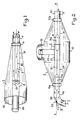
- FIG. 2 represents a load according to the invention, the internal elements of which are seen by transparency.
- This charge comprises a metal casing 1 with a cylindrical part, 12, of axis XX terminated at its two ends by truncated cones.
- the envelope 1 also comprises a cylinder 13, of axis, not shown, perpendicular to the axis XX; this cylinder 13 is external to the cylindrical part 12, to which it is welded at one of its ends; the cylindrical part 12 is pierced with a hole whose contour is in line with the internal walls of the cylinder 13.
- FIG. 2 also shows that the casing 1 is traversed right through, along the axis XX, by a tube formed successively of a copper pipe 40 into which a conductive liquid arrives (arrow f) by a lateral entry, a short metal pipe, forming a ring, 11 a, welded to the casing 1, an insulating pipe 30, a metal tube 21 placed substantially above the cylinder 13, an insulating pipe 31 identical to the pipe 30, a ring 11 identical to the ring 11a and also welded to the casing 1, and a copper pipe 41 used to remove the conductive liquid (arrow f ').
- the metal envelope 1 consists of two "half-envelopes" assembled by screws: one on which the rings 11a and 11b are welded and the other which comprises the cylinder 13 .
- the tube formed by the parts 40, 11 a, 30, 21, 31, 11 b, 41 of FIG. 2 is a continuous tube, the elements of which are assembled by flanges.
- This tube has a straight part, of axis XX, and is bent at one of its ends (bent pipe 40); a set "suction and discharge pump - cooling means", not shown, circulates in this tube a conductive liquid which penetrates through the pipe 40 (arrow f) and resort through the pipe 41 (arrow f ').
- the shape of a large, continuous cylinder, of constant cross section, presented by the tube in which the conductive liquid circulates, makes it possible to move two insulating cores 5a, 5b, made of polytetrafluoroethylene. These cores are interconnected by a connecting bar 51 while another bar, 50, connects the core 5a to a mechanical adjustment device, not shown, since it is not of interest for understanding the invention and does not not part of the actual microwave load; the bar 50 crosses the pipe 40, in its bent part, by a seal 52.
- the cores 5a, 5b of Figure 2 form with the bars 50, 51 a rigid assembly which, by the adjustment device mentioned above, can be moved in translation (double arrow g) along the axis XX.
- the microwave load which has just been described with the aid of FIG. 2 can be adjusted in terms of impedance value; in fact by the displacement of the insulating cores 5a, 5b it is possible to reduce more or less the quantity of conductive liquid which is contained in the insulating pipes 30, 31, and which alone constitutes the resistive part of the microwave load; the conductive liquid contained in the metal pipes 40, 11 a, 21, 11 b, 41, in fact represents resistances which are short-circuited by these metal pipes.
- the load according to FIG. 2 measures 2.30 m overall in its largest dimension and has been designed to operate as a dummy antenna of 800 kW, in frequency bands located around 30 MHz.
- FIG. 3 A microwave load similar to the load according to FIG. 2 is shown in FIG. 3.
- This load differs from the previous load only with regard to the bent shape of the pipe 41 which is, here, identical to the bent pipe 40 and also has a gasket, 52 ', and with respect to how the insulating cores 5a and 5b can slide inside the tube in which the conductive liquid circulates.
- the core 5a is still integral with the bar 50 which makes it possible to move it along the axis XX (double arrow g) but is no longer integral with the core 5b; indeed the hub 5b is integral with a bar 50 'which passes through the seal 52' allowing adjustment, by translation (double arrow g '), of the position of the core 5b in the tube where the conductive liquid circulates.
- the mechanical adjustment device not shown, which controlled, in the example described, the displacement of the cores 5a, 5b (FIG. 3), ensured a symmetrical displacement of these cores; that is to say that the core 5a could move between a first position where it was entirely contained in the pipes 40 and 11 a and a second position where it was entirely contained in the insulating pipe 30 while, at the same speed, the core 5b could move between a first position where it was entirely contained in the pipes 41 and 11 b and a second position where it was entirely contained in the insulating pipe 31.
- the first position of the cores corresponds to the minimum value of the resistance of the contents of the insulating pipes 30 and 31 and therefore of the microwave load; the second position corresponds to the minimum value.
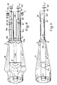
- FIGS. 4 and 5 are respectively a top view and a side view of the same load according to the invention.
- This load corresponds substantially to the loads according to Figures 2 and 3 but in which the tube where the conductive liquid circulates (40-11a-30-21-31-11b-41, Figures 2 and 3) would have been folded in the middle (21 ) to form a U of uniform section.
- This structure is particularly favorable because already the fact of folding the tube leads to a gain in space, that is to say a less bulky load with equivalent characteristics; moreover, in FIGS.
- the parts of the load comprising the cylinders of conductive liquid (contained in pipes 30 and 31) each had to have a characteristic impedance of 100 ohms, since they were connected to a circuit d input (elements 13 and 20) of selected characteristic impedance equal to 50 ohms; on the other hand, in the embodiment according to FIGS.
- Figures 4 and 5 show the U-shaped tube in which the conductive liquid circulates.
- the base of the U is formed by a bent copper pipe, 21, in which the direction of flow of the liquid (arrow f ") rotates 180 °.
- the - U is formed, for each of its branches, of an insulating pipe, 30, 31, of one half of a conductive part, 11, the two halves of which correspond to the assembly side by side of the rings 11a, 11b of FIGS.
- the envelope, 1, of the microwave load according to FIGS. 4 and 5, comprises a kind of aluminum skirt, 10, welded, on the conductive part 11 at one of its ends and which widens up to beyond the bent pipe 21 to then shrink and form the outer conductor of the coaxial cable which constitutes the access of the load.
- the inner conductor of the access coaxial cable consists of a hollow metallic element, 20, the cylindrical shape of which is modified in the vicinity of the base of the U-shaped hydraulic circuit; the hollow element 20 forms, with the bent pipe 21 to which it is welded, a single metal part 2.
- two insulating cores 5a, 5b, of elongated shape are provided respectively, provided in the vicinity of one of their ends with insulating guide pins, such as e, arranged at 120 ° from each other.
- These cores can be moved by translation in the direction of the large dimension of the branches of the U, thanks to a mechanical assembly whose part specific to the load is formed by a "endless" metal screw 60, 60 ', associated with a nut formed by a metal plate 61, 61 ', integral with the core and pierced with a threaded hole crossed by the corresponding metal screw 60, 60'.
- the "endless" screws are partially arranged in the insulating pipes 40, 41 from which they emerge through the seals 52, 52 '; the screws 60, 60 'are only threaded over a portion of their length located inside the insulating tubes 40,41; their end external to the insulating tube comprises a toothed wheel, 62, 62 ′, while their other end abuts in a bowl hollowed out in the conductive part 11.
- the toothed wheels 62, 62 ' are coupled to a motor, not shown, by a chain, also not shown.
- the motor therefore drives the screws 60, 60 'in a rotational movement on themselves (arrows r and r'); the rotation of the motor being able to be controlled in both directions, this makes it possible to control the direction of the translational movement which results therefrom for the insulating cores 5a, 5b.
- the load according to FIGS. 4 and 5 has an overall length of 1.30 meters; this load has been designed to operate as a 800 kW dummy antenna in frequency bands around 30 MHz.
- the invention which has just been described is not limited to the example described, it relates more generally to the use of an insulating device placed in the hydraulic circuit with liquid conducting a microwave load , and whose position inside this circuit can be modified so as to more or less reduce the volume of conductive liquid located in the areas of the hydraulic circuit where this conductive liquid contributes to constituting the impedance of the load. It is also understood that when it comes to an insulating device is meant very generally a device whose conductivity is significantly lower than that of the conductive liquid used in the load.
- the pipes 40, 41 of FIGS. 2 to 5, as well as the pipe 4 of FIG. 1, can be both conductive pipes and insulating pipes.
Landscapes
- Physics & Mathematics (AREA)
- General Physics & Mathematics (AREA)
- Engineering & Computer Science (AREA)
- Microelectronics & Electronic Packaging (AREA)
- Constitution Of High-Frequency Heating (AREA)
Claims (6)
Applications Claiming Priority (2)
| Application Number | Priority Date | Filing Date | Title |
|---|---|---|---|
| FR8301455A FR2540281A1 (fr) | 1983-01-31 | 1983-01-31 | Charge hyperfrequence a liquide conducteur, pour generateur de grande puissance |
| FR8301455 | 1983-01-31 |
Publications (2)
| Publication Number | Publication Date |
|---|---|
| EP0117778A1 EP0117778A1 (de) | 1984-09-05 |
| EP0117778B1 true EP0117778B1 (de) | 1987-09-02 |
Family
ID=9285441
Family Applications (1)
| Application Number | Title | Priority Date | Filing Date |
|---|---|---|---|
| EP19840400152 Expired EP0117778B1 (de) | 1983-01-31 | 1984-01-24 | Höchstfrequenzabsorber mit Flüssigkeitsleiter für Hochleistungsgenerator |
Country Status (3)
| Country | Link |
|---|---|
| EP (1) | EP0117778B1 (de) |
| DE (1) | DE3465839D1 (de) |
| FR (1) | FR2540281A1 (de) |
Families Citing this family (2)
| Publication number | Priority date | Publication date | Assignee | Title |
|---|---|---|---|---|
| FR2718584B1 (fr) * | 1994-04-08 | 1996-05-31 | Thomcast | Charge de puissance à refroidissement par air et antenne fictive constituée par une telle charge. |
| CN111934074B (zh) * | 2020-07-23 | 2021-05-07 | 南京航空航天大学 | 一种用于大功率微波测量的宽带液体衰减器 |
Family Cites Families (1)
| Publication number | Priority date | Publication date | Assignee | Title |
|---|---|---|---|---|
| US3350671A (en) * | 1966-07-27 | 1967-10-31 | Jr Robert C Seamans | High power-high voltage waterload |
-
1983
- 1983-01-31 FR FR8301455A patent/FR2540281A1/fr active Granted
-
1984
- 1984-01-24 EP EP19840400152 patent/EP0117778B1/de not_active Expired
- 1984-01-24 DE DE8484400152T patent/DE3465839D1/de not_active Expired
Also Published As
| Publication number | Publication date |
|---|---|
| DE3465839D1 (en) | 1987-10-08 |
| FR2540281A1 (fr) | 1984-08-03 |
| EP0117778A1 (de) | 1984-09-05 |
| FR2540281B1 (de) | 1985-04-05 |
Similar Documents
| Publication | Publication Date | Title |
|---|---|---|
| EP2146395B1 (de) | Anschlussmuffe eines Supraleiterkabels und Abschluss des Anschlusses mit Hilfe dieser Muffe | |
| EP1703611A1 (de) | Elektrische Durchführung für supraleitendes Element | |
| EP0283414A2 (de) | Sicherung mit Umhüllung aus fester Keramik hoher Dichte und Herstellungsverfahren dieser Sicherung | |
| EP0374062B1 (de) | Verfahren und Vorrichtung zur Trocknung der Papierisolation eines elektrotechnischen Hochspannungsapparates und Mikrowellenenergieapplikationsvorrichtung zu diesem Zweck | |
| FR2550017A1 (fr) | Charge calorimetrique a micro-ondes | |
| FR3074364A1 (fr) | Charge interne pour tube a ondes progressives utilisant une ligne a retard en guide replie | |
| FR2487573A1 (fr) | Ensemble de fenetre a micro-onde et tube a micro-onde muni d'un tel ensemble | |
| FR2977381A1 (fr) | Dephaseur et repartiteur de puissance | |
| EP0117778B1 (de) | Höchstfrequenzabsorber mit Flüssigkeitsleiter für Hochleistungsgenerator | |
| CA1299241C (fr) | Resistance de freinage pour reseau electrique a haute tension | |
| EP0153541B1 (de) | Rundes Fernster für einen Mikrowellenhohlleiter | |
| EP2325939B1 (de) | Vorrichtung zum Multiplexen von thermisch optimierten Hyperfrequenzkanälen | |
| EP0487043B1 (de) | Verfahren zur Kühlung einer Stromzuleitung für elektrische Anlagen mit sehr niedrigen Temperaturen und Vorrichtung zur Durchführung des Verfahrens | |
| EP2038978B1 (de) | Elektrische durchführungsstruktur für ein supraleitendes element | |
| WO1998020576A1 (fr) | Dispositif de filtrage a cavite metallique a inserts dielectriques | |
| CA1074878A (fr) | Transition hyperfrequence | |
| EP2417680B1 (de) | Elektrischer leiter mit verbesserter kühlung und elektrisches gerät in einem versiegelten gehäuse, das mindestens einen solchen leiter umfasst | |
| WO2012055923A1 (fr) | Appareillage electrique sous enveloppe metallique comportant au moins un capot pare-effluve assurant des echanges convectifs | |
| CA1236152A (fr) | Generateur electrique de vapeur | |
| FR2637731A1 (fr) | Tube a onde progressive muni d'un dispositif de couplage etanche entre sa ligne a retard et un circuit hyperfrequence externe | |
| WO2010012803A1 (fr) | Conducteur electrique a refroidissement ameliore et dispositif de commutation sous enveloppe etanche comportant au moins un tel conducteur | |
| FR2500707A1 (fr) | Dispositif de traitement de materiaux par hyper-frequences a elements modulaires | |
| EP1191654A1 (de) | Installationsrohr für einen elektrische Kabel und Verfahren zur Kontrolle der elektrischen Installation des installierten Kabels | |
| CA2167364A1 (fr) | Amenee de courant haute tension entre une application supraconductrice a basse temperature critique et une extremite de connexion a temperature ambiante d'un cable d'energie hautetension | |
| FR2525812A1 (fr) | Circuit a onde lente pour un tube a ondes progressives |
Legal Events
| Date | Code | Title | Description |
|---|---|---|---|
| PUAI | Public reference made under article 153(3) epc to a published international application that has entered the european phase |
Free format text: ORIGINAL CODE: 0009012 |
|
| AK | Designated contracting states |
Designated state(s): CH DE GB LI |
|
| 17P | Request for examination filed |
Effective date: 19850114 |
|
| 17Q | First examination report despatched |
Effective date: 19861112 |
|
| GRAA | (expected) grant |
Free format text: ORIGINAL CODE: 0009210 |
|
| AK | Designated contracting states |
Kind code of ref document: B1 Designated state(s): CH DE GB LI |
|
| REF | Corresponds to: |
Ref document number: 3465839 Country of ref document: DE Date of ref document: 19871008 |
|
| GBT | Gb: translation of ep patent filed (gb section 77(6)(a)/1977) | ||
| PLBE | No opposition filed within time limit |
Free format text: ORIGINAL CODE: 0009261 |
|
| STAA | Information on the status of an ep patent application or granted ep patent |
Free format text: STATUS: NO OPPOSITION FILED WITHIN TIME LIMIT |
|
| 26N | No opposition filed | ||
| PGFP | Annual fee paid to national office [announced via postgrant information from national office to epo] |
Ref country code: CH Payment date: 19911210 Year of fee payment: 9 |
|
| PGFP | Annual fee paid to national office [announced via postgrant information from national office to epo] |
Ref country code: DE Payment date: 19911214 Year of fee payment: 9 |
|
| PGFP | Annual fee paid to national office [announced via postgrant information from national office to epo] |
Ref country code: GB Payment date: 19911219 Year of fee payment: 9 |
|
| PG25 | Lapsed in a contracting state [announced via postgrant information from national office to epo] |
Ref country code: GB Effective date: 19930124 |
|
| PG25 | Lapsed in a contracting state [announced via postgrant information from national office to epo] |
Ref country code: LI Effective date: 19930131 Ref country code: CH Effective date: 19930131 |
|
| GBPC | Gb: european patent ceased through non-payment of renewal fee |
Effective date: 19930124 |
|
| REG | Reference to a national code |
Ref country code: CH Ref legal event code: PL |
|
| PG25 | Lapsed in a contracting state [announced via postgrant information from national office to epo] |
Ref country code: DE Effective date: 19931001 |