EP0117778B1 - Hyperfrequency load with conductive liquid for high power generator - Google Patents
Hyperfrequency load with conductive liquid for high power generator Download PDFInfo
- Publication number
- EP0117778B1 EP0117778B1 EP19840400152 EP84400152A EP0117778B1 EP 0117778 B1 EP0117778 B1 EP 0117778B1 EP 19840400152 EP19840400152 EP 19840400152 EP 84400152 A EP84400152 A EP 84400152A EP 0117778 B1 EP0117778 B1 EP 0117778B1
- Authority
- EP
- European Patent Office
- Prior art keywords
- tube
- insulating
- tubes
- load
- hyperfrequency
- Prior art date
- Legal status (The legal status is an assumption and is not a legal conclusion. Google has not performed a legal analysis and makes no representation as to the accuracy of the status listed.)
- Expired
Links
Images

Classifications
-
- H—ELECTRICITY
- H01—ELECTRIC ELEMENTS
- H01P—WAVEGUIDES; RESONATORS, LINES, OR OTHER DEVICES OF THE WAVEGUIDE TYPE
- H01P1/00—Auxiliary devices
- H01P1/24—Terminating devices
- H01P1/26—Dissipative terminations
- H01P1/262—Dissipative terminations the dissipative medium being a liquid or being cooled by a liquid
-
- G—PHYSICS
- G01—MEASURING; TESTING
- G01R—MEASURING ELECTRIC VARIABLES; MEASURING MAGNETIC VARIABLES
- G01R1/00—Details of instruments or arrangements of the types included in groups G01R5/00 - G01R13/00 and G01R31/00
- G01R1/20—Modifications of basic electric elements for use in electric measuring instruments; Structural combinations of such elements with such instruments
- G01R1/203—Resistors used for electric measuring, e.g. decade resistors standards, resistors for comparators, series resistors, shunts
-
- H—ELECTRICITY
- H01—ELECTRIC ELEMENTS
- H01C—RESISTORS
- H01C10/00—Adjustable resistors
- H01C10/02—Liquid resistors
Definitions
- the present invention relates to microwave loads used to test high power generators and more particularly to loads with conductive liquid.
- the present invention it is possible to reduce the aforementioned drawbacks thanks, in particular, to a device making it possible to adjust the impedance of the microwave load to maintain it or bring it to the desired value.
- a microwave charge with conductive liquid for high power generator, comprising a first and a second conductive metal part, electrically isolated from each other and forming between them the access of the load, and a circuit hydraulic formed of pipes in communication with each other and containing a conductive liquid, these pipes comprising: conductive pipes which, for a first and a second part, are in contact respectively with the first and the second part, and insulating pipes situated in series between the pipes of the first and of the second part, is mainly characterized by an insulating device placed inside the hydraulic circuit and leaves means for introducing,. over an adjustable length, the insulating device into the insulating pipes.
- the pipe 30 is surrounded, over its entire part located inside the casing 10, by another insulating pipe, 31, fixed to the ring 11 and the internal wall of which is in the extension of the internal wall of the ring ; similarly, on its part located outside the casing 10, the pipe 30 is surrounded by a copper cylinder, 4, the internal wall of which is in the extension of the internal wall of the ring 11.
- the end of the insulating pipe 31, opposite the ring 11, is covered with a bent pipe, 21, conductive of electricity and forming a cap which completely obstructs the opening of the pipe 31.
- the pipe 21 is made of copper ; it is made integral, by welding on its face opposite the pipe 31, with a hollow metal tube 20, which emerges from the conical envelope 10 through the middle of the widest opening of this envelope.
- the load according to FIG. 1 has a coaxial access, which is constituted by the casing 10 at the place of its widest opening and by the tube 20.
- a conductive liquid formed of baking soda dissolved in the water
- the conductive liquid enters through the insulating pipe 30, arrives in the bent metal pipe 21, and leaves through the space between the pipe 30 and, successively the insulating pipe 31, the metal ring 11 and the cylinder 4; arrows indicate, in Figure 1, the path followed by the liquid through the charge.
- the liquid is used on the one hand for the evacuation of calories and on the other hand to constitute a resistive element by the volume of liquid contained in the pipe 31 (both between pipes 30 and 31 as inside the part of pipe 30 included in pipe 31).
- the load which has just been described with the aid of FIG. 1 has the drawbacks mentioned above with regard to the known microwave loads.
- the invention proposes to compensate for the drops in resistance of the conductive liquid, due to the rise in temperature, by an adjustable reduction in the quantity of liquid which forms the resistive cylinder (contained in the pipe 31 of FIG. 1) and this by more or less introducing an insulating device into the resistive cylinder in order to decrease the quantity of liquid that it contains and, therefore, to increase its resistance.
- the introduction of an insulating device into the resistive cylinder 31 poses, in use, space problems for accommodating the insulating device; this is why various forms of charges have been studied to facilitate this introduction.
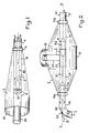
- FIG. 2 represents a load according to the invention, the internal elements of which are seen by transparency.
- This charge comprises a metal casing 1 with a cylindrical part, 12, of axis XX terminated at its two ends by truncated cones.
- the envelope 1 also comprises a cylinder 13, of axis, not shown, perpendicular to the axis XX; this cylinder 13 is external to the cylindrical part 12, to which it is welded at one of its ends; the cylindrical part 12 is pierced with a hole whose contour is in line with the internal walls of the cylinder 13.
- FIG. 2 also shows that the casing 1 is traversed right through, along the axis XX, by a tube formed successively of a copper pipe 40 into which a conductive liquid arrives (arrow f) by a lateral entry, a short metal pipe, forming a ring, 11 a, welded to the casing 1, an insulating pipe 30, a metal tube 21 placed substantially above the cylinder 13, an insulating pipe 31 identical to the pipe 30, a ring 11 identical to the ring 11a and also welded to the casing 1, and a copper pipe 41 used to remove the conductive liquid (arrow f ').
- the metal envelope 1 consists of two "half-envelopes" assembled by screws: one on which the rings 11a and 11b are welded and the other which comprises the cylinder 13 .
- the tube formed by the parts 40, 11 a, 30, 21, 31, 11 b, 41 of FIG. 2 is a continuous tube, the elements of which are assembled by flanges.
- This tube has a straight part, of axis XX, and is bent at one of its ends (bent pipe 40); a set "suction and discharge pump - cooling means", not shown, circulates in this tube a conductive liquid which penetrates through the pipe 40 (arrow f) and resort through the pipe 41 (arrow f ').
- the shape of a large, continuous cylinder, of constant cross section, presented by the tube in which the conductive liquid circulates, makes it possible to move two insulating cores 5a, 5b, made of polytetrafluoroethylene. These cores are interconnected by a connecting bar 51 while another bar, 50, connects the core 5a to a mechanical adjustment device, not shown, since it is not of interest for understanding the invention and does not not part of the actual microwave load; the bar 50 crosses the pipe 40, in its bent part, by a seal 52.
- the cores 5a, 5b of Figure 2 form with the bars 50, 51 a rigid assembly which, by the adjustment device mentioned above, can be moved in translation (double arrow g) along the axis XX.
- the microwave load which has just been described with the aid of FIG. 2 can be adjusted in terms of impedance value; in fact by the displacement of the insulating cores 5a, 5b it is possible to reduce more or less the quantity of conductive liquid which is contained in the insulating pipes 30, 31, and which alone constitutes the resistive part of the microwave load; the conductive liquid contained in the metal pipes 40, 11 a, 21, 11 b, 41, in fact represents resistances which are short-circuited by these metal pipes.
- the load according to FIG. 2 measures 2.30 m overall in its largest dimension and has been designed to operate as a dummy antenna of 800 kW, in frequency bands located around 30 MHz.
- FIG. 3 A microwave load similar to the load according to FIG. 2 is shown in FIG. 3.
- This load differs from the previous load only with regard to the bent shape of the pipe 41 which is, here, identical to the bent pipe 40 and also has a gasket, 52 ', and with respect to how the insulating cores 5a and 5b can slide inside the tube in which the conductive liquid circulates.
- the core 5a is still integral with the bar 50 which makes it possible to move it along the axis XX (double arrow g) but is no longer integral with the core 5b; indeed the hub 5b is integral with a bar 50 'which passes through the seal 52' allowing adjustment, by translation (double arrow g '), of the position of the core 5b in the tube where the conductive liquid circulates.
- the mechanical adjustment device not shown, which controlled, in the example described, the displacement of the cores 5a, 5b (FIG. 3), ensured a symmetrical displacement of these cores; that is to say that the core 5a could move between a first position where it was entirely contained in the pipes 40 and 11 a and a second position where it was entirely contained in the insulating pipe 30 while, at the same speed, the core 5b could move between a first position where it was entirely contained in the pipes 41 and 11 b and a second position where it was entirely contained in the insulating pipe 31.
- the first position of the cores corresponds to the minimum value of the resistance of the contents of the insulating pipes 30 and 31 and therefore of the microwave load; the second position corresponds to the minimum value.
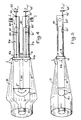
- FIGS. 4 and 5 are respectively a top view and a side view of the same load according to the invention.
- This load corresponds substantially to the loads according to Figures 2 and 3 but in which the tube where the conductive liquid circulates (40-11a-30-21-31-11b-41, Figures 2 and 3) would have been folded in the middle (21 ) to form a U of uniform section.
- This structure is particularly favorable because already the fact of folding the tube leads to a gain in space, that is to say a less bulky load with equivalent characteristics; moreover, in FIGS.
- the parts of the load comprising the cylinders of conductive liquid (contained in pipes 30 and 31) each had to have a characteristic impedance of 100 ohms, since they were connected to a circuit d input (elements 13 and 20) of selected characteristic impedance equal to 50 ohms; on the other hand, in the embodiment according to FIGS.
- Figures 4 and 5 show the U-shaped tube in which the conductive liquid circulates.
- the base of the U is formed by a bent copper pipe, 21, in which the direction of flow of the liquid (arrow f ") rotates 180 °.
- the - U is formed, for each of its branches, of an insulating pipe, 30, 31, of one half of a conductive part, 11, the two halves of which correspond to the assembly side by side of the rings 11a, 11b of FIGS.
- the envelope, 1, of the microwave load according to FIGS. 4 and 5, comprises a kind of aluminum skirt, 10, welded, on the conductive part 11 at one of its ends and which widens up to beyond the bent pipe 21 to then shrink and form the outer conductor of the coaxial cable which constitutes the access of the load.
- the inner conductor of the access coaxial cable consists of a hollow metallic element, 20, the cylindrical shape of which is modified in the vicinity of the base of the U-shaped hydraulic circuit; the hollow element 20 forms, with the bent pipe 21 to which it is welded, a single metal part 2.
- two insulating cores 5a, 5b, of elongated shape are provided respectively, provided in the vicinity of one of their ends with insulating guide pins, such as e, arranged at 120 ° from each other.
- These cores can be moved by translation in the direction of the large dimension of the branches of the U, thanks to a mechanical assembly whose part specific to the load is formed by a "endless" metal screw 60, 60 ', associated with a nut formed by a metal plate 61, 61 ', integral with the core and pierced with a threaded hole crossed by the corresponding metal screw 60, 60'.
- the "endless" screws are partially arranged in the insulating pipes 40, 41 from which they emerge through the seals 52, 52 '; the screws 60, 60 'are only threaded over a portion of their length located inside the insulating tubes 40,41; their end external to the insulating tube comprises a toothed wheel, 62, 62 ′, while their other end abuts in a bowl hollowed out in the conductive part 11.
- the toothed wheels 62, 62 ' are coupled to a motor, not shown, by a chain, also not shown.
- the motor therefore drives the screws 60, 60 'in a rotational movement on themselves (arrows r and r'); the rotation of the motor being able to be controlled in both directions, this makes it possible to control the direction of the translational movement which results therefrom for the insulating cores 5a, 5b.
- the load according to FIGS. 4 and 5 has an overall length of 1.30 meters; this load has been designed to operate as a 800 kW dummy antenna in frequency bands around 30 MHz.
- the invention which has just been described is not limited to the example described, it relates more generally to the use of an insulating device placed in the hydraulic circuit with liquid conducting a microwave load , and whose position inside this circuit can be modified so as to more or less reduce the volume of conductive liquid located in the areas of the hydraulic circuit where this conductive liquid contributes to constituting the impedance of the load. It is also understood that when it comes to an insulating device is meant very generally a device whose conductivity is significantly lower than that of the conductive liquid used in the load.
- the pipes 40, 41 of FIGS. 2 to 5, as well as the pipe 4 of FIG. 1, can be both conductive pipes and insulating pipes.
Description
La présente invention se rapporte aux charges hyperfréquences utilisées pour tester les générateurs de grande puissance et plus particulièrement aux charges à liquide conducteur.The present invention relates to microwave loads used to test high power generators and more particularly to loads with conductive liquid.
Il est connu d'utiliser des charges à liquide conducteur pour faire des mesures avec des générateurs hyperfréquences de grande puissance. Dans ces charges le liquide conducteur circule dans un circuit hydraulique grâce à un pompe associée à des moyens de refroidissement, et sert d'une part d'impédance de charge quand il passe dans une portion du circuit hydraulique formée de tuyaux isolants et d'autre part de moyen d'évacuation des calories produits dans la portion du circuit où il sert d'impédance de charge. Or la conductivité des liquides conducteurs employés dans ces charges varie très fortement avec la température; c'est ainsi que, avec le bicarbonate de soude dissous dans l'eau qui est un liquide conducteur couramment employé, la conductivité double lorsque la température augmente de 40°C. Il s'en suit que l'impédance des charges hyperfréquences connues, utilisant des liquides conducteurs, varie au fur et à mesure que la température varie; comme rien ne permet de compenser ces variations il faut attendre qu'un état d'équilibre des températures soit établi pour faire des mesures. De plus, si les mesures doivent être effectuées pour différentes températures du liquide conducteur correspondant à différentes puissances de sortie du générateur, il faut, soit prévoir des moyens de refroidissement suffisants pour rendre aussi faible que possible l'écart entre ces différentes températures, soit changer de charge lorsque les conditions d'expérimentation sont modifiées. Ce sont là des solutions onéreuses, souvent peu commodes et nécessitant du temps pour leur mise en oeuvre: attente de la température d'équilibre, temps nécessaire au remplacement d'une charge par une autre.It is known to use conductive liquid charges to make measurements with high power microwave generators. In these loads the conductive liquid circulates in a hydraulic circuit thanks to a pump associated with cooling means, and serves on the one hand for load impedance when it passes through a portion of the hydraulic circuit formed of insulating pipes and on the other hand share of means for evacuating the calories produced in the portion of the circuit where it serves as load impedance. Now the conductivity of the conductive liquids used in these charges varies very strongly with the temperature; thus, with baking soda dissolved in water which is a commonly used conductive liquid, the conductivity doubles when the temperature increases by 40 ° C. It follows that the impedance of known microwave loads, using conductive liquids, varies as the temperature varies; as there is nothing to compensate for these variations, it is necessary to wait until a state of equilibrium of temperatures is established before making measurements. In addition, if the measurements have to be made for different temperatures of the conductive liquid corresponding to different generator output powers, it is necessary either to provide sufficient cooling means to make the difference between these different temperatures as small as possible, or to change when the experimental conditions are changed. These are expensive solutions, often inconvenient and requiring time for their implementation: waiting for the equilibrium temperature, time required to replace one load with another.
Par la présente invention il est possible de réduire les inconvénients précités grâce, en particulier, à un dispositif permettant de régler l'impédance de la charge hyperfréquence pour la maintenir ou l'amener à la valeur désirée.By the present invention it is possible to reduce the aforementioned drawbacks thanks, in particular, to a device making it possible to adjust the impedance of the microwave load to maintain it or bring it to the desired value.
Selon l'invention une charge hyperfréquence à liquide conducteur, pour générateur de grande puissance, comportant une première et une seconde pièce métallique conductrice, isolées électriquement l'une de l'autre et formant entre elles l'accés de la charge, et un circuit hydraulique formé de tuyaux en communication entre eux et contenant un liquide conducteurs, ces tuyaux comportant: des tuyaux conducteurs qui, pour une première et une deuxième partie, sont en contact respectivement avec la première et la second pièce, et des tuyaux isolants situés en série entre les tuyaux de la première et de la deuxième partie, est principalement caractérisée par un dispositif isolant placé à l'intérieur du circuit hydraulique et part des moyens pour introduire,.sur une longueur réglable, le dispositif isolant dans les tuyaux isolants.According to the invention a microwave charge with conductive liquid, for high power generator, comprising a first and a second conductive metal part, electrically isolated from each other and forming between them the access of the load, and a circuit hydraulic formed of pipes in communication with each other and containing a conductive liquid, these pipes comprising: conductive pipes which, for a first and a second part, are in contact respectively with the first and the second part, and insulating pipes situated in series between the pipes of the first and of the second part, is mainly characterized by an insulating device placed inside the hydraulic circuit and leaves means for introducing,. over an adjustable length, the insulating device into the insulating pipes.
La présente invention sera mieux comprise et d'autres caractéristiques apparaîtront à l'aide de la description ci-après et des figures s'y rapportant qui représentent:The present invention will be better understood and other characteristics will appear with the aid of the description below and of the figures relating thereto which represent:
la figure 1, une charge hyperfréquence selon l'art connu,
- -les figures 2 et 3, deux exemples de réalisation de charges selon l'invention,
- -les figures 4 et 5 deux vues d'une autre charge selon l'invention.
- FIGS. 2 and 3, two exemplary embodiments of loads according to the invention,
- FIGS. 4 and 5 two views of another load according to the invention.
Sur les différentes figures les éléments correspondants sont désignés par les mêmes repères et les différentes pièces cachées par d'autres sont dessinées comme si elles étaient vues par transparence.In the various figures, the corresponding elements are designated by the same references and the various parts hidden by others are drawn as if they were seen by transparency.
La figure 1 montre une charge hyperfréquence de type connu, à circulation de liquide conducteur. Cette charge se présente sensiblement sous la forme d'un entonnoir, traversé longitudinalement par un tube double. Elle comporte une enveloppe sensiblement conique, 10, en aluminium, constituant l'entonnoir; à l'ouverture la plus étroite de l'enveloppe 10 est situé un tuyau court ou bague, 11, en bronze, soudé à l'enveloppe. Un tuyau isolant 30, en stratifié de fibres de verre et de résine, traverse le trou de la bague 11 au centre de cette bague, pour pénérer dans l'enveloppe sur une longueur égale environ aux deux tiers de la longueur hors-tout de l'entonnoir. Le tuyau 30 est entouré, sur toute sa partie située à l'intérieur de l'enveloppe 10, par un autre tuyau isolant, 31, fixé à la bague 11 et dont la paroit interne est dans le prolongement de la paroi interne de la bague; de même, sur sa partie située à l'extérieur de l'enveloppe 10, le tuyau 30 est entouré d'un cylindre en cuivre, 4, dont la paroi interne est dans le prolongement de la paroi interne de la bague 11.FIG. 1 shows a microwave load of known type, with circulation of conductive liquid. This charge is substantially in the form of a funnel, traversed longitudinally by a double tube. It comprises a substantially conical envelope, 10, of aluminum, constituting the funnel; at the narrowest opening of the
L'extrémité du tuyau isolant 31, opposé à la bague 11, est recouverte d'un tuyau coudé, 21, conducteur de l'électricité et formant un capuchon qui obstrue complètement l'ouverture du tuyau 31. Le tuyau 21 est fabriqué en cuivre; il est rendu solidaire, par soudure sur sa face opposée au tuyau 31, d'un tube métallique creux 20, qui ressort de l'enveloppe conique 10 par le milieu de l'ouverture la plus large de cette enveloppe.The end of the
La charge selon la figure 1 comporte un accès coaxial, qui se trouve constitué par l'enveloppe 10 à l'endroit de son ouverture la plus large et par le tube 20. Dans cette charge circule un liquide conducteur formé de bicarbonate de soude dissous dans l'eau; sous l'action d'une pompe, non représentée, associée à des moyens de refroidissement, également non représentés, le liquide conducteur pénètre par le tuyau isolant 30, arrive dans le tuyau métallique coudé 21, et repart par l'espace compris entre le tuyau 30 et, successivement le tuyau isolant31, la bague métallique 11 et le cylindre 4; des flèches indiquent, sur la figure 1, le trajet suivi par le liquide à travers la charge. Dans le circuit hydraulique ainsi constitué, le liquide sert d'une part à l'évacuation des calories et d'autre part à constituer un élément résistif par le volume de liquide contenu dans le tuyau 31 (que ce soit entre les tuyaux 30 et 31 que à l'intérieur de la partie du tuyau 30 comprise dans le tuyau 31).The load according to FIG. 1 has a coaxial access, which is constituted by the
La charge qui vient d'être décrite à l'aide de la figure 1 présente les inconvénients mentionnés plus avant au sujet des charges hyperfréquences connues. L'invention propose de compenser les baisses de résistances du liquide conducteur, dues à l'élévation de température, par une réduction réglable de la quantité de liquide qui forme le cylindre résistif (contenu dans le tuyau 31 de la figure 1) et ceci en introduisant plus ou-moins un dispositif isolant dans le cylindre résistif afin de diminuer la quantité de liquide qu'il comporte et, donc, d'augmenter sa résistance. Mais, avec une charge telle que celle selon la figure 1, l'introduction d'un dispositif isolant dans le cylindre résistif 31 pose, à l'usage, des problèmes de place pour loger le dispositif isolant; c'est pourquoi diverses formes de charges ont été étudiées pour faciliter cette introduction.The load which has just been described with the aid of FIG. 1 has the drawbacks mentioned above with regard to the known microwave loads. The invention proposes to compensate for the drops in resistance of the conductive liquid, due to the rise in temperature, by an adjustable reduction in the quantity of liquid which forms the resistive cylinder (contained in the
La figure 2 représente une charge selon l'invention dont les éléments internes sont vus par transparence. Cette charge comporte une enveloppe métallique 1 avec une partie cylindrique, 12, d'axe XX terminée à ses deux extrémités par des troncs de cône. L'enveloppe 1 comporte également un cylindre 13, d'axe, non représenté, perpendiculaire, à l'axe XX; ce cylindre 13 est extérieur à la partie cylindrique 12, à laquelle il est soudé à l'une de ses extémités; la partie cylindrique 12 est percée d'un trou dont le contour est dans le prolongement des parois internes du cylindre 13.FIG. 2 represents a load according to the invention, the internal elements of which are seen by transparency. This charge comprises a
La figure 2 montre également que l'enveloppe 1 est traversée de part en part, selon l'axe XX, par un tube formé successivement d'un tuyau en cuivre 40 dans lequel un liquide conducteur arrive (flèche f) par une entrée latérale, d'un tuyau métallique court, formant une bague, 11 a, soudée à l'enveloppe 1, d'un tuyau isolant 30, d'un tube métallique 21 placé sensiblement à l'aplomb du cylindre 13, d'un tuyau isolant 31 identique au tuyau 30, d'une bague 11 identique à la bague 11a et également soudée à l'enveloppe 1, et d'un tuyau en cuivre 41 servant à évacuer le liquide conducteur (flèche f').FIG. 2 also shows that the
Pour sa réalisation pratique, il est à noter que l'enveloppe métallique 1 est constituée de deux "demi-envelopes" assemblées par vis: l'une sur laquelle sont soudées les bagues 11 a et 11b et l'autre qui comporte le cylindre 13.For its practical realization, it should be noted that the
Sur la figure 2, apparaît un tube 20, réalisé en cuivre. Le tube 20 est situé à l'intérieur du cylindre 13, et est concentrique avec le cylindre 13; le tube 20 se prolonge jusqu'au tube métallique 21 à la paroi duquel il est soudé. L'accès de la charge selon la figure 2 est un accès coaxial dont les conducteurs sont constitués par les éléments 20 et 13.In Figure 2, appears a
Le tube que forment les pièces 40, 11 a, 30, 21, 31, 11 b, 41 de la figure 2, est un tube continu dont les éléments sont assemblés par brides. Ce tube présente une partie droite, d'axe XX, et est coudé à l'une de ses extrémités (tuyau coudé 40); un ensemble "pompe aspirante et refoulante--moyens de refoidissement", non représenté, fait circuler dans ce tube un liquide conducteur qui pénètre par le tuyau 40 (flèche f) et resort par le tuyau 41 (flèche f').The tube formed by the
La forme de cylindre large et continu, à section constante, que présente le tube dans lequel circule le liquide conducteur, permet d'y faire déplacer deux noyaux isolants 5a, 5b, en polytétrafluo- roéthylène. Ces noyaux sont reliés entre eux par une barre de liaison 51 tandis qu'une autre barre, 50, relie le noyau 5a à un dispositif mécanique de réglage non représenté, car ne présentant par d'intérêt pour la compréhension de l'invention et ne faisant pas partie de la charge hyperfréquence proprement dite; la barre 50 traverse le tuyau 40, dans sa partie coudée, par un joint d'étanchéite 52.The shape of a large, continuous cylinder, of constant cross section, presented by the tube in which the conductive liquid circulates, makes it possible to move two
Les noyaux 5a, 5b de la figure 2, forment avec les barres 50, 51 un ensemble rigide qui, par le dispositif de réglage mentionné ci-avant, peut être déplacé en translation (double flèche g) suivant l'axe XX. Trois ergots isolants, tels que e, disposés sur chacun des deux noyaux, à 120° les uns des autres autour de l'axe XX, sont en contact avec la paroi interne du tube où circule le liquide conducteur; ces ergots contribuent à ce que les noyaux isolants 5a, 5b puissent être déplacés selon l'axe XX.The
La charge hyperfréquence qui vient d'être décrite à l'aide de la figure 2 peut être réglée en valeur d'impédance; en effet par le déplacement des noyaux isolants 5a, 5b il est possible de réduire plus ou moins la quantité de liquide conducteur qui est contenue dans les tuyaux isolants 30, 31, et qui constitue à elle seule la partie résistive de la charge hyperfréquence; le liquide conducteur contenu dans les tuyaux métalliques 40, 11 a, 21, 11 b, 41, représente en effet des résistances qui sont court-circuitées par ces tuyaux métalliques. La valeur de la résistance des cylindres de liquide conducteur contenus dans les tuyaux isolants 30, 31 est ainsi réglable, pour une température donnée, d'une valeur minimale, qui est obtenue lorsque les noyaux 5a, 5b sont respectivement tout entiers introduits dans les tuyaux conducteurs 40, 21, à une valeur maximale, qui est obtenu lorsque les noyaux 5a, 5b sont respectivement tout entiers introduits dans les tuyaux isolants 30, 31; il est ainsi possible de maintenir cette résistance à une valeur constant quelle que soit la température du liquide, du moins dans les limites admissibles.The microwave load which has just been described with the aid of FIG. 2 can be adjusted in terms of impedance value; in fact by the displacement of the
La charge selon la figure 2 mesure 2,30 m hors-tout dans sa plus grande dimension et a été étudiée pour fonctionner en antenne fictive de 800 kW, dans des bandes de fréquences situées aux alentours de 30 MHz.The load according to FIG. 2 measures 2.30 m overall in its largest dimension and has been designed to operate as a dummy antenna of 800 kW, in frequency bands located around 30 MHz.
Une charge hyperfréquence analogue à la charge selon la figure 2 est représentée sur la figure 3. Cette charge ne se distingue de la charge précédente qu'en ce qui concerne la forme coudée du tuyau 41 qui est, ici, identique au tuyau coudé 40 et comporte aussi un joint d'étanchéité, 52', et en ce que concerne la façon dont les noyaux isolants 5a et 5b peuvent coulisser à l'intérieur du tube dans lequel circule le liquid conducteur. Le noyau 5a est toujours solidaire de la barre 50 qui permet de le déplacer selon l'axe XX (double flèche g) mais n'est plus solidaire du noyau 5b; en effet le moyau 5b est solidaire d'une barre 50' qui traverse le joint d'étanchéite 52' permettant le réglage, par translation (double flèche g'), de la position du noyau 5b dans le tube où circule le liquide conducteur. Le dispositif mécanique de réglage, non représenté, qui commandait, dans l'exemple décrit, le déplacement des noyaux 5a, 5b (figure 3), assurait un déplacement symétrique de ces noyaux; c'est-à-dire que le noyau 5a pouvait se déplacer entre une première position où il était tout entier contenu dans les tuyaux 40 et 11 a et une seconde position où il était tout entier contenu dans le tuyau isolant 30 pendant que, à la même vitesse, le noyau 5b pouvait se déplacer entre une première position où il était tout entier contenu dans les tuyaux 41 et 11 b et une seconde position où il était tout entier contenu dans le tuyau isolant 31. La première position des noyaux correspond à la valeur minimale de la résistance du contenu des tuyaux isolants 30 et 31 et donc de la charge hyperfréquence; la seconde position correspond à la valeur minimale.A microwave load similar to the load according to FIG. 2 is shown in FIG. 3. This load differs from the previous load only with regard to the bent shape of the
Les figures 4 et 5 sont respectivement une vue de dessus et une vue de côté d'une même charge selon l'invention. Cette charge correspond sensiblement aux charges selon les figures 2 et 3 mais dans lesquelles le tube où circule le liquide conducteur (40-11a-30-21-31-11b-41, figures 2 et 3) aurait été replié en son milieu (21) pour former un U de section uniforme. Cette structure est particulièrement favorable car déjà le fait de replier le tube amène-un gain de place, c'est-à-dire une charge moins volumineuse à caractéristiques équivalentes; de plus, dans les figures 2 et 3, les parties de la charge comportant les cylindres de liquide conducteur (contenus dans les tuyaux 30 et 31) devaient chacune présenter une impédance caractéristique de 100 ohms, puisqu'elles venaient se raccorder sur un circuit d'entrée (éléments 13 et 20) d'impédance caractéristique choisie égale à 50 ohms; par contre dans la réalistion selon les figures 4 et 5 c'est la même partie de l'enveloppe extérieure 1 de la charge hyperfréquence qui entoure les cylindres de liquide conducteur (contenus dans les tuyaux 30 et 31), il en résulte que, pour une impédance caractéristique du circuit d'entrée de la charge hyperfrequence égale à 50 ohms, l'impédance caractéristique de la partie contenant les cylindres de liquide conducteur placés en parallèle sous une enveloppe extérieure commune, ne doit plus être que de 50 ohms; d'où, là encore un gain de place.Figures 4 and 5 are respectively a top view and a side view of the same load according to the invention. This load corresponds substantially to the loads according to Figures 2 and 3 but in which the tube where the conductive liquid circulates (40-11a-30-21-31-11b-41, Figures 2 and 3) would have been folded in the middle (21 ) to form a U of uniform section. This structure is particularly favorable because already the fact of folding the tube leads to a gain in space, that is to say a less bulky load with equivalent characteristics; moreover, in FIGS. 2 and 3, the parts of the load comprising the cylinders of conductive liquid (contained in
Les figures 4 et 5 montrent le tube en U dans lequel circule le liquide conducteur. La base du U est formé par un tuyau coudé, en cuivre, 21, dans lequel le sens d'écoulement du liquide (flèche f") tourne de 180°. A partir du tuyau 21, le- U est formé, pour chacune de ses branches, d'un tuyau isolant, 30, 31, d'une moitié d'une pièce conductrice, 11, dont les deux moitiés correpondant à l'assemblage côte à côte des bagues 11a, 11b des figures 2 et 3, et d'un tuyau conducteur, 40, 41, fermé partiellement à son extrémité opposée à la pièce conductrice, la seule ouverture à cette extrémité étant assurée par un joint d'étanchéité, 52, 52'; et l'arrivée (flèche f) de liquide conducteur dans le U est assurée par un conduit latéral débouchant dans le tuyau 40, tandis que le départ (flèche f) se fait par un autre conduit latéral débouchant dans le tuyau 41. L'assemblage des tuyaux composant le U où circule le liquide conducteur, se fait par brides de raccordement.Figures 4 and 5 show the U-shaped tube in which the conductive liquid circulates. The base of the U is formed by a bent copper pipe, 21, in which the direction of flow of the liquid (arrow f ") rotates 180 °. From the
L'enveloppe, 1, de la charge hyperfréquence selon les figures 4 et 5, comporte une sorte de jupe en aluminium, 10, soudée, sur la pièce conductrice 11 à l'une de ses extrémités et que va en s'évasant jusqu'au delà du tuyau coudé 21 pour, ensuite, se rétrécir et former le conducteur exterior du câble coaxial qui constitue l'accès de la -charge. Le conducteur intérieur du câble coaxial d'accès est constitué par un élément métallique creux, 20, dont la forme cylindrique est modifiée au voisinage de la base du circuit hydraulique en U; l'élément creux 20 forme, avec le tuyau coudé 21 auquel il est soudé, une pièce métallique unique 2.The envelope, 1, of the microwave load according to FIGS. 4 and 5, comprises a kind of aluminum skirt, 10, welded, on the
Dans les deux branches du circuit hydraulique en U des figures 4 et 5, sont disposés respectivement deux noyaux isolants 5a, 5b, de forme allongée, munis au voisinage d'une de leurs extrémités d'ergots de guidage, isolants, tels que e, disposés à 120° les uns des autres. Ces noyaux peuvent être déplacés par translation dans le sens de la grande dimension des branches du U, grâce à un ensemble mécanique dont la partie propre à la charge est formée d'une vis métallique "sans fin" 60, 60', associé à un écrou formé d'une plaquette métallique 61, 61', solidaire du noyau et percée d'un trou fileté traversé par la vis métallique 60, 60' correspondante. Les vis "sans fin" sont disposées partiellement dans les tuyaux isolants 40, 41 dont elles ressortent par les joints d'étanchéité 52, 52'; les vis 60, 60' ne sont filetées que sur une portion de leur longueur située à l'intérieur des tubes isolants 40,41 ; leur extrémité extérieure au tube isolant comporte une roue dentée, 62, 62', tandis que leur autre extémité vient en butée dans une cuvette creusée dans la pièce conductrice 11.In the two branches of the U-shaped hydraulic circuit of FIGS. 4 and 5, two
Les roues dentées 62, 62' sont acouplées à un moteur, non représenté, par une chaîne, également non représentée. Le moteur entraîne donc les vis 60, 60' dans un mouvement de rotation sur elles-mêmes (flèches r et r'); la rotation du moteur pouvant être commandée dans les deux sens cela permet de commander le sens du mouvement de translation qui en résulte pour les noyaux isolants 5a, 5b. Comme dans le cas des figures 2 et 3, il est ainsi possible de régler la valeur de la résistance présentée par les cylindres de liquide conducteur, contenus dans les tuyaux isolants 30 et 31: la valeur minimale est obtenu lorsque les noyaux sont dans les tuyaux 40, 41 et la valeur maximale quand les noyaux ont pénétré aux maximum dans les tuyaux isolants 30, 31.The
Entre son accès coaxial et les roues dentées 62, 62', la charge selon les figures 4 et 5 a une longueur hors tout de 1,30 mètre; cette charge a été étudiée pour fonctionner commen antenne fictive de 800 kW dans des bandes de fréquences situées aux alentours de 30 MHz.Between its coaxial access and the
L'invention qui vient d'être décrite n'est pas limitée à l'exemple décrit, elle porte d'une façon plus générale sur l'utilisation d'un dispositif isolant placé dans le circuit hydraulique à liquide conducteur d'une charge hyperfréquence, et dont la position à l'intérieur de ce circuit peut être modifiée de manière à réduire plus ou moins le volume de liquide conducteur situé dans les zones du circuit hydraulique où ce liquide conducteur contribue à constituer l'impédance de la charge. Il est entendu par ailleurs que lorsqu'il est question de dispositif isolant il faut entendre d'une façon très générale un dispositif dont la conductivité est nettement inférieure à celle du liquide conducteur utilisé dans la charge.The invention which has just been described is not limited to the example described, it relates more generally to the use of an insulating device placed in the hydraulic circuit with liquid conducting a microwave load , and whose position inside this circuit can be modified so as to more or less reduce the volume of conductive liquid located in the areas of the hydraulic circuit where this conductive liquid contributes to constituting the impedance of the load. It is also understood that when it comes to an insulating device is meant very generally a device whose conductivity is significantly lower than that of the conductive liquid used in the load.
Il est de plus à noter que les tuyaux 40, 41 des figures 2 à 5, de même d'ailleurs que le tuyau 4 de la figure 1, peuvent aussi bien être des tuyaux conducteurs que des tuyaux isolants.It should also be noted that the
Claims (6)
Applications Claiming Priority (2)
| Application Number | Priority Date | Filing Date | Title |
|---|---|---|---|
| FR8301455A FR2540281A1 (en) | 1983-01-31 | 1983-01-31 | CONDUCTIVE LIQUID HYPERFREQUENCY LOAD FOR HIGH POWER GENERATOR |
| FR8301455 | 1983-01-31 |
Publications (2)
| Publication Number | Publication Date |
|---|---|
| EP0117778A1 EP0117778A1 (en) | 1984-09-05 |
| EP0117778B1 true EP0117778B1 (en) | 1987-09-02 |
Family
ID=9285441
Family Applications (1)
| Application Number | Title | Priority Date | Filing Date |
|---|---|---|---|
| EP19840400152 Expired EP0117778B1 (en) | 1983-01-31 | 1984-01-24 | Hyperfrequency load with conductive liquid for high power generator |
Country Status (3)
| Country | Link |
|---|---|
| EP (1) | EP0117778B1 (en) |
| DE (1) | DE3465839D1 (en) |
| FR (1) | FR2540281A1 (en) |
Families Citing this family (2)
| Publication number | Priority date | Publication date | Assignee | Title |
|---|---|---|---|---|
| FR2718584B1 (en) * | 1994-04-08 | 1996-05-31 | Thomcast | Air-cooled power load and dummy antenna formed by such a load. |
| CN111934074B (en) * | 2020-07-23 | 2021-05-07 | 南京航空航天大学 | Broadband liquid attenuator for high-power microwave measurement |
Family Cites Families (1)
| Publication number | Priority date | Publication date | Assignee | Title |
|---|---|---|---|---|
| US3350671A (en) * | 1966-07-27 | 1967-10-31 | Jr Robert C Seamans | High power-high voltage waterload |
-
1983
- 1983-01-31 FR FR8301455A patent/FR2540281A1/en active Granted
-
1984
- 1984-01-24 EP EP19840400152 patent/EP0117778B1/en not_active Expired
- 1984-01-24 DE DE8484400152T patent/DE3465839D1/en not_active Expired
Also Published As
| Publication number | Publication date |
|---|---|
| FR2540281A1 (en) | 1984-08-03 |
| DE3465839D1 (en) | 1987-10-08 |
| EP0117778A1 (en) | 1984-09-05 |
| FR2540281B1 (en) | 1985-04-05 |
Similar Documents
| Publication | Publication Date | Title |
|---|---|---|
| EP2146395B1 (en) | Sleeve for connecting a superconductor cable and connection termination via this sleeve | |
| EP0283414A2 (en) | Fuse with high density ceramic casing and method of fabrication of that fuse | |
| EP0374062B1 (en) | Process and apparatus for drying the paper insulation of a high-tension electrotechnical device, and microwave energy applicator for this purpose | |
| FR2487573A1 (en) | MICROWAVE WINDOW ASSEMBLY AND MICROWAVE TUBE PROVIDED WITH SUCH AN ASSEMBLY | |
| FR2546340A1 (en) | TUNABLE HYPERFREQUENCY FILTER COAXIAL-TYPE DIALER-TYPE BAND STICK WITH DIELECTRIC RESONATORS | |
| EP0336337A1 (en) | Current limiter | |
| FR2977381A1 (en) | DEHASTER AND POWER DISTRIBUTOR | |
| EP0117778B1 (en) | Hyperfrequency load with conductive liquid for high power generator | |
| CA1299241C (en) | Braking resistor for a high voltage electrical network | |
| EP0153541B1 (en) | Circular window for a microwave waveguide | |
| EP0487043B1 (en) | Cooling process of a current supply line of an electrical unit at very low temperature and device for carrying it out | |
| EP2038978B1 (en) | Electric feedthrough structure for superconductor element | |
| WO1998020576A1 (en) | Filtering device with metal cavity provided with dielectric inserts | |
| CA2714127A1 (en) | Thermically optimized hyperfrequency channel multiplexing device and signal repeating device equipped with at least one such multiplexing device | |
| EP2633538B1 (en) | Electrical apparatus in a metal case said apparatus comprising at least one corona-shield cap ensuring convective exchange | |
| CA1074878A (en) | Hyperfrequency transition | |
| EP2417680B1 (en) | Electric conductor with improved cooling and electric appliance in a sealed housing comprising at least one such conductor | |
| CA1236152A (en) | Electric steam generator | |
| FR2637731A1 (en) | PROGRESSIVE WAVE TUBE PROVIDED WITH A WATERPROOF COUPLING DEVICE BETWEEN THE DELAYED LINE AND AN EXTERNAL MICROWAVE CIRCUIT | |
| WO2010012803A1 (en) | Electrical conductor with improved cooling and switching device in a sealed casing comprising at least one such conductor | |
| FR2500707A1 (en) | Microwave material processor with detachable radiating elements - uses waveguide coupler with coaxial tappings along its length to permit fitting of different radiating elements | |
| EP1191654A1 (en) | Installation conduit for an electrical cable and control process for the electrical isolation of the installed cable | |
| CA2167364A1 (en) | High voltage supply between a superconductor at low critical temporature, and the ambiant temperature connection termination of a high voltage cable | |
| FR2525812A1 (en) | SLOW WAVE CIRCUIT FOR PROGRESSIVE WAVE TUBE | |
| WO1996039011A1 (en) | Slow-wave high-power discharge cavity operating in the radiofrequency range |
Legal Events
| Date | Code | Title | Description |
|---|---|---|---|
| PUAI | Public reference made under article 153(3) epc to a published international application that has entered the european phase |
Free format text: ORIGINAL CODE: 0009012 |
|
| AK | Designated contracting states |
Designated state(s): CH DE GB LI |
|
| 17P | Request for examination filed |
Effective date: 19850114 |
|
| 17Q | First examination report despatched |
Effective date: 19861112 |
|
| GRAA | (expected) grant |
Free format text: ORIGINAL CODE: 0009210 |
|
| AK | Designated contracting states |
Kind code of ref document: B1 Designated state(s): CH DE GB LI |
|
| REF | Corresponds to: |
Ref document number: 3465839 Country of ref document: DE Date of ref document: 19871008 |
|
| GBT | Gb: translation of ep patent filed (gb section 77(6)(a)/1977) | ||
| PLBE | No opposition filed within time limit |
Free format text: ORIGINAL CODE: 0009261 |
|
| STAA | Information on the status of an ep patent application or granted ep patent |
Free format text: STATUS: NO OPPOSITION FILED WITHIN TIME LIMIT |
|
| 26N | No opposition filed | ||
| PGFP | Annual fee paid to national office [announced via postgrant information from national office to epo] |
Ref country code: CH Payment date: 19911210 Year of fee payment: 9 |
|
| PGFP | Annual fee paid to national office [announced via postgrant information from national office to epo] |
Ref country code: DE Payment date: 19911214 Year of fee payment: 9 |
|
| PGFP | Annual fee paid to national office [announced via postgrant information from national office to epo] |
Ref country code: GB Payment date: 19911219 Year of fee payment: 9 |
|
| PG25 | Lapsed in a contracting state [announced via postgrant information from national office to epo] |
Ref country code: GB Effective date: 19930124 |
|
| PG25 | Lapsed in a contracting state [announced via postgrant information from national office to epo] |
Ref country code: LI Effective date: 19930131 Ref country code: CH Effective date: 19930131 |
|
| GBPC | Gb: european patent ceased through non-payment of renewal fee |
Effective date: 19930124 |
|
| REG | Reference to a national code |
Ref country code: CH Ref legal event code: PL |
|
| PG25 | Lapsed in a contracting state [announced via postgrant information from national office to epo] |
Ref country code: DE Effective date: 19931001 |