EP0117592A1 - Mähdrescher - Google Patents
Mähdrescher Download PDFInfo
- Publication number
- EP0117592A1 EP0117592A1 EP84200235A EP84200235A EP0117592A1 EP 0117592 A1 EP0117592 A1 EP 0117592A1 EP 84200235 A EP84200235 A EP 84200235A EP 84200235 A EP84200235 A EP 84200235A EP 0117592 A1 EP0117592 A1 EP 0117592A1
- Authority
- EP
- European Patent Office
- Prior art keywords
- straw
- discharge
- shaft
- combine harvester
- assist means
- Prior art date
- Legal status (The legal status is an assumption and is not a legal conclusion. Google has not performed a legal analysis and makes no representation as to the accuracy of the status listed.)
- Granted
Links
Images


Classifications
-
- A—HUMAN NECESSITIES
- A01—AGRICULTURE; FORESTRY; ANIMAL HUSBANDRY; HUNTING; TRAPPING; FISHING
- A01F—PROCESSING OF HARVESTED PRODUCE; HAY OR STRAW PRESSES; DEVICES FOR STORING AGRICULTURAL OR HORTICULTURAL PRODUCE
- A01F12/00—Parts or details of threshing apparatus
- A01F12/44—Grain cleaners; Grain separators
- A01F12/442—Rotary cleaners
-
- A—HUMAN NECESSITIES
- A01—AGRICULTURE; FORESTRY; ANIMAL HUSBANDRY; HUNTING; TRAPPING; FISHING
- A01D—HARVESTING; MOWING
- A01D41/00—Combines, i.e. harvesters or mowers combined with threshing devices
- A01D41/12—Details of combines
Definitions
- the present invention relates to combine harvesters and has particular reference to such machines having rotary separating mechanisms.
- grain is threshed and separated in a threshing and separating mechanism and the separated grain, together with the impurities, such as chaff, dust, straw particles, and tailings, is fed to a cleaning mechanism for cleaning.
- Clean grain is collected below the cleaning mechanism and fed to a grain tank for temporary storage.
- the tailings are separated from the clean grain and impurities for reprocessing. This reprocessing either involves recyling the tailings through the threshing and separating mechanism or treating them in a separate tailings rethreshing means.
- grain refers to that -part of the crop which is threshed and separated from the discardable part of the crop material which is referred to as "straw”. Incompletely threshed ears are referred to as "tailings”.
- forward when used in connection with the combine harvester and/or components thereof are determined with reference to the direction of forward operative travel of the combine harvester but should not be construed as limiting.
- a conventional transversely-extending, threshing mechanism having a threshing cylinder and a cooperable concave is combined with a rotary separating mechanism having a rotor of a width greater than that of the threshing mechanism and disposed parallel thereto with its ends extending transversely past the respective ends of the threshing mechanism.
- the rotary separating mechanism operates spirally to convey the crop material received from the threshing mechanism towards each of its ends, whilst submitting the crop to a separating action.
- the incoming layer of crop material has to be divided in two substantially equal portions, each of which is then spirally conveyed from the centre of the separating mechanism to one or other of its ends.
- the straw issuing from the ends of the separating mechanism is discharged from the machine through respective discharge channels which are called straw hoods, the straw being deflected downwardly at the ends of the straw hoods for final discharge to the ground either through respective discharge openings, or a single opening to which both streams of straw are directed to form a central windrow.
- a single straw hood and discharge opening may be provided.
- the straw is propelled through the or each straw hood by the separating rotor but in certain circumstances, the straw may not be propelled far enough through the or each discharge channel, whereby it falls short thereof and is discharged onto the steerable wheels and/or the associated wheel axle of the machine which are normally located in the vicinity of the front edge of the or each discharge opening.
- Discharge of straw in any relatively large quantity onto the steerable wheels and/or the associated wheel axle gives rise to two problems; the first is that the straw can be subjected to further breakage by the wheels and pressed against the ground surface in compacted form rather than in a fluffy windrow as is desired, and the second is that straw can bridge the or each wheel and/or associated wheel axle and build up to such an extent that the or each straw hood can be blocked.
- Such blockage or plugging of the machine can only be removed manually with consequential downtime of the machine and can also result in machine damage.
- a combine harvester comprises a rotary separating mechanism operable to separate grain from crop material, means operable to project straw in a desired path for discharge from the machine through a discharge opening, and rotary straw discharge assist means located below said desired path and between the separating mechanism and the discharge opening.
- the separating mechanism may itself provide the basic straw discharge means although one or more separate beaters may be employed.
- the assist means comprise a shaft from which project a plurality of blades extending substantially the full width of the discharge channel and each having a turned radially outer edge which trails the body of the blade as seen in the direction of rotation.
- the separating mechanism comprises a rotor arranged to move crop material to each end during the separating action and to discharge straw from each end, rotary straw discharge assist means being associated with each end of the separating rotor.
- the two discharge assist means are mounted on a common shaft which is driven from the separating mechanism although this is not essential.
- the or each discharge assist means is rotated in ; a direction opposite to that of the separating mechanism.
- each discharge assist means operates primarily in the manner of a fan, whereby a stream of air is produced generally in the direction of the desired path of crop material to assist in keeping the latter confined to that path.
- the crop material may have a tendency to deviate from the desired path and fall on the discharge assist means in which case, the latter positively deflects the crop material back into the desired path. This minimal contact between the crop material and the discharge assist means helps considerably in minimising crop breakage and power consumption.
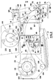
- the combine harvester generally indicated at 1, comprises a main chassis or frame 2 supported on a front pair of drive wheels 3 and a rear pair of steerable wheels 4. Supported on the main chassis 2 are an operator's platform 5 with a driver's seat 6 and a steering wheel 7, a grain tank 8, a threshing and separating mechanism indicated generally at 9, a grain cleaning mechanism 11 and an engine (not shown).
- a conventional heacer 12and straw elevator 13 extend forwardly of the main chassis 2, and the header is pivotally secured to the chassis for generally vertical movement which is controlled by extensible hydraulic cylinders 14.
- the combine harvester 1 As the combine harvester 1 is propelled forwardly over a field with standing crop, the latter is severed from the stubble by a sickle bar 10 on the header 12, whereafter a reel 15 and a header auger ' 16 convey the cut crop to the straw elevator 13 which supplies it to the threshing and separating mechanism 9.
- the crop received within the threshing and separating mechanism 9 is threshed and separated that is to say the crop (which may be wheat, corn, rice, soybeans, rye, grass seed, barley, oats or other similar crops) is rubbed and beaten, whereby the grain, seed or the like, is loosened and separated from the straw, stalks, coils or other discardable part of the crop.
- Grain which has been separated from the straw falls onto the grain cleaning mechanism 11 which comprises means to separate chaff and other impurities from the grain, and means to separate unthreshed materials (tailings). Cleaned grain is then elevated into the grain tank 8 and the tailings are reprocessed in separate tailings rethreshers (not shown) and returned to the cleaning mechanism 11 for repeat cleaning action.
- the header 12 is of the grain type, but clearly other forms of header may be employed (for example a corn header), depending on the crop to be harvested.
- a threshing portion 17 of the threshing and separating mechanism 9 comprises a rotatable threshing cylinder 18 cooperable with a stationary threshing concave 19. Rearwardly of the threshing mechanism 17, a deflector beater, or so-called straw beater, 21 with an associated beater grate is provided.
- the straw beater 21 has a smaller diameter than the threshing cylinder 18 and is arranged above the level of the discharge end of the threshing concave 19.
- the straw beater 21 and beater grate have substantially the same width as the threshing mechanism 17.
- a separator portion of the threshing and separating mechanism 9 comprises a first separator rotor or cylinder 22 and a second rotor or cylinder 23 cooperable with respective concaves 24 and 25.
- the second rotor 23 is mounted within a separator housing 26 and both of these components have a width substantially exceeding the width of the first rotor 22 which is the same width as the beater 21 and the threshing mechanism 17.
- the rotor housing 26 has a width approximately twice that of the rotor 22.
- the mat of crop material received by the separator rotor 23 from tbe separator, rotor 22 is divided into two (by means not shown) and the resulting two portions moved spirally around the rotor 23 to respective ends thereof to complete the separating action.
- the mats of crop material are propelled by the rotor through respective straw hoods 27 for discharge from the machine.
- the crop material (straw) is discharged from the machine in one of two ways.
- the straw is discharged in a central windrow by virtue of the two independent streams of straw first being deflected by pivotable deflectors 28 (disposed in the broken line positions of Figure 4), inwardly of the machine.
- the deflectors 28 are pivoted to a position in which they lie against respective sidewalls 31 of the machine, thereby allowing the straw issuing from the ends of the rotor 23 to flow parallel to the sidewalls until it reaches further deflectors 32 which deflect the straw downwardly to respective straw choppers 33.
- the straw choppers 33 are rotary devices and they propel chopped straw through respective discharge outlets 34 which are inclined downwardly and flare outwardly, as seen in plan view ( Figure 4), and are effective to spread the straw across the full width of the machine and beyond, this spreading action being assisted by inclined vanes 35 provided within each outlet.
- each discharge assist means 36 in the form of a rotor comprising a shaft 37 (common to both assist means - Figure 3) on which are keyed two spaced collars 38 having four equispaced lugs 40 to which are attached respective rotor blades 39 extending radially of the shaft and along the full width of the discharge channel 27.
- the radially outer edge of each blade 39 is turned through 90 0 in a direction which trails with respect to the direction of rotation of the rotor, which is clockwise as seen in Figure 2.
- Each discharge assist means 36 is provided with a protective shield 41 extending generally below the rotor.
- Arcuate shields 42 are attached to the opposed sidewalls 31, 43 of each straw hood 27 to prevent straw from becoming wrapped around the shaft 37.
- Each shield 42 has a flange 44 extending a short distance axially of the shaft 37.
- the discharge assist means 36 are driven from the separator rotor 23 via a belt 45 extending between a pulley 46 on the rotor 23 and a pulley 47 on the shaft 37, via a reversing pulley 48, and a tension pulley 49.
- the discharge assist means 36 are rotated clockwise, as already mentioned, which is contrary to the direction of rotation of the rotor 23.
- the shaft 37 is journalled in four bearings 50 mounted in respective sidewalls 31 and in intermediate . walls 50', as seen in Figure 3.
- the desired path of the straw in being transported from the rotor 23 to the rear, discharge end of the machine is indicated at 51 and it will be seen that each discharge assist means 36 is located below this path between the rotor 23 and the discharge end of the machine.
- the discharge assist means 36 do not engage the straw which is important as regards the mode of operation in which the straw is formed into a central windrow. This is because the threshing rotor 18 and the separator rotors 22, 23 have relatively aggressive actions on the crop material with a tendency to produce shorter and more broken pieces of straw than a machine not employing rotary separating means. Therefore, any engagement of the straw with the discharge assist means would increase the likelihood of straw chopping and breakage which is undesirable when the straw is to be conserved for baling, for example.
- each discharge assist means 36 is primarily that of a fan, whereby a stream of air is produced generally in the direction of the desired path 51 of straw discharge to assist in keeping the straw confined to that path.
- the blades 39 serve positively to deflect the straw in the intended paths 51 and thus prevent it from being discharged from the machine prematurely and in all likelihood on to the steerable wheels 4 and associated wheel axle with the possible consequence of the straw building up on these components and eventually blocking the entire straw discharge facilities of the machine.
- This arrangement of the discharge assist means 36 not only minimises straw breakage, unlike the discharge beaters of known machines, but also minimises power consumption (due to minimal contact with the straw) which is another very important consideration.
- the deflectors 28 are shown in greater detail in Figure 5 and are in the form of doors hinged at 52 about a generally vertical axis, the hinges being secured to the respective sidewalls 31.
- Latches 53 are provided for securing the deflectors in the selected position, the latches comprising, for each deflector, a pair of latch members 54 pivoted at 55 to the deflectors and also pivoted at 56 to an actuating bar 57.
- Each latch member 54 has an extension 58 which passes through an associated slot in an edge flange 59 of. the deflector 28 for engagement with a slot in a bracket 61 attached to the adjacent sidewall 31 ( Figure 5) when the deflectors are positioned so as to allow straw to pass to the straw choppers 33.
- the latch member extensions 58 engage respective slots in respective vertical beams 62 which are part of the chassis 2.
- Each bar 57 is formed with a handle 63 at the lower end and the other end is attached to the associated deflector 28 by a spring 64, the bar being movable in a generally downward vertical direction against the spring to pivot the latch members 54 and so release the latch member extensions 58 from either the slots in the brackets 61 or the slots in the beams 62, as the case may be.
- the deflectors 28 can then be swung to the alternative position and the handles 63 released, whereby the springs 64 pull the handles upwardly, thus pivoting the latch members clockwise as seen in Figure 5 to engage the extensions 58 with the newly selected slots. Movement of the bars 57 is guided by respective brackets 65 attached to the deflectors 28 and having slots through which the bars pass.
- the two straw choppers 33 are mounted on respective shafts 66 ( Figure 2) which carry axially spaced lugs 67 to which are pivotally attached clusters of knives 68.
- the knives 68 cooperate with stationary blades 69 adjustably mounted in a panel 71 associated with each chopper 33.
- Each panel 71 has a Straight portion which acts as the deflector 32, to deflect straw into the related chopper 33, followed by an arcuate portion 73 complementary to the circle generated by the tips of the rotating knives 68, which portion acts to guide straw to the outlets 34, and terminating in another generally ⁇ straight portion 74 forming the top of the related outlet 34.
- the straw choppers 33 are driven from a shaft 75 which in turn is driven by the engine (not shown) via a belt 76 extending around an input pulley 77 mounted on one end of the shaft 75 by bearings 78, whereby it is rotatable relative to the shaft when a magnetic clutch 79 is inoperative.
- the clutch 79 is rendered operative, the pulley 7 * 7 is clutched to the shaft 75, whereby the latter is driven, and hence the straw choppers 33 are driven in a clockwise direction (as seen in Figure 2) via respective pulleys 81 on the shaft 75, pulleys 82 on the shafts 66, and belts 83.
- the pulley 77 is continuously rotated but the clutch 79 is actuated only when the straw choppers 33 are required for use.
- each chopper unit 33 is such that the straw is moved overtop with respect to the chopper rotors as it moves from the chopper inlets to the stationary knives 69.
- the transfer of straw through the chopper units 33 is generally aligned with the path 51 of the straw within the straw hoods 27 immediately prior to entering the chopper units, whereby the movement of the straw is smooth and without any abrupt change of direction which reduces greatly the risk of plugging.
- the straw chopper drive shaft 75 is mounted in a special manner and is in fact floatingly mounted in order to maintain tension in the belt 76 and the two belts 83 without the need to employ the usual tension pulleys.
- this end of the shaft needs to be capable of two degrees of movement to be able to tension both belts.
- the other end of the shaft 75 needs only to be capable of one degree of movement since only one of the belts 83 is associated therewith.
- Figures 6 to 9 show the details of the mounting of the shaft 75.
- a parallelogram linkage arrangement generally indicated at 84 and comprising a generally horizontal beam 85 attached to a portion 86 of the main frame or chassis 2 of the machine, a beam 87 generally parallel to the beam 85 and carrying a bearing housing 88 for the associated end of the shaft 75, a generally upright beam 89 pivotally attached at respective ends to the beams 85 and 87, and a rod 91 generally parallel to the beam 89 and also pivotally attached at respective ends to the beams 85 and 87.
- the beam 89 As seen in Figure 9, the beam 89
- the rod 91 is pivotally attached at the lower end to a lug 90 carried by the beam 87 and is slidingly received towards its other end in a slot in a hexagonal abutment member 94 which is pivotally mounted between two arms 95 extending from the beam 85 by respective spigots 96.
- a compression spring 97 providing tensioning means for the belt 83 acts between a flat on the hexagonal member 94 and a further abutment in the form of a washer 98 provided on the rod 91 and held in a selected position by a nut 99 received on the upper and threaded end of the rod.
- a cylinder 101 is placed over the spring 97 and serves to limit the compression of the latter by acting between the washer 98 and member 94 when the compression limit is reached.
- the bearing housing 88 for the end of the shaft 75 is pivotally connected via a plate 100 to one end of a further rod l02 which is also slidingly received in a slot in a further hexagonal abutment member l03 similar to the member 94, the member l03 being mounted between spaced arms l04 and 104' ( Figure 9) extending from the beam 85.
- a compression spring l05 providing tensioning means for the belt 76 acts between a flat on the hexagonal member 103 and a washer 106 held by a nut l07 on the outer and threaded end of the rod 102, again a cylinder l08 enveloping the spring in order to limit compression thereof.
- a self-aligning (spherical) bearing 109 is mounted in the bearing housing 88 and the shaft 75 is journalled therein.
- the springs l05 and 97 serve to urge the related end of the shaft 75 to the right and upwardly, respectively, (as seen in Figure 6) in order to tension the belts 76 and 83, the one movement being independent of the other by virtue of the parallelogram mounting arrangement for this end of the shaft.
- the spring 105 urges the rod 102 to the right as seen in Figure 6, this moves the bearing housing 88, and hence shaft 75 and beam 87, in the same direction, the spring thus effectively acting on the parallelogram arrangement.
- Movement of the beam 87 results in the lower ends of the beam 89 and rod 91 also moving to the right whilst simultaneously pivoting and thus not imparting any substantial vertical movement to the shaft 75 which would affect the tension in one or both belts 83.
- the spring 97 urges the rod l02 upwardly which pulls the beam 87, and hence bearing housing 88 and shaft 75, upwardly to tension the belt 83 without significantly affecting the tension in the belt 76.
- the spring 115 urges the rod 112 upwardly which pulls the beam 111 carrying a bearing housing 117 for the shaft 75 and movement of the beam thus moves the bearing housing and the shaft, whereby the related belt 83 is tensioned.
- a self-aligning (spherical) bearing 118 is provided in the housing 117 for the shaft 75. It will be appreciated that the self-aligning bearings l09 and 118 at respective ends of the shaft 75 allow movement of one end for belt tensioning purposes independent of movement of the other end. Further, it will be appreciated that the tension in the belts 76 and 83 is automatically maintained (whereby belt stretch is constantly compensated), and that the initial tension can be set by adjusting the nuts 99, 107 and 110 and hence altering the compressions of the related springs.
- the combine harvester is provided with the usual air screen 119 through which air is drawn for cooling the engine coolant and/or transmission fluid, the air screen comprising a perforated member 121 in the form of a cylinder closed at one end, save for the perforations in the end as well as in the body, and mounted for rotation.
- a stationary sector 122 ( Figure 2) which is inperforate and serves to blank off the perforations in successive portions of the member (both at the end and in the body) as the latter rotates past the sector.
- the sector 122 is arranged at the lowermost portion of the member 121 but in the illustrated embodiment, this means immediately adjacent the top 123 of one of the straw hoods 27 since the air screen 119 is mounted on a panel 124 of the main frame 2 over that straw hood.
- a transversely extending and generally upright panel 125 extends from the panel 124, whereby the air screen 119 is generally confined at one side and at its lower end which therefore increases the risk of foreign matter being re-circulated on the air screen rather than falling clear thereof.
- the aperture 127 is rectangular (as shown in Figure 4) and extends transversely of the machine, with an upwardly and forwardly inclined deflector 128 being provided along the downstream edge with respect to the direction of rotation of the air screen.
- a shield 129 extends from the outer edge of the deflector 128, beneath the air screen member 121, to the transverse panel 125.
- the shield 129 is located at the outer edge of the top 123 of the straw hood 27.
- the deflector 128 is formed with a flange 131 by which it is attached to the underside of the top 123 of the straw hood 27, this arrangement providing a smooth surface over which the foreign matter and straw can flow which would not be the case if the flange 131 were attached to the upper side of the top 123. The latter arrangement could result in build-up of material leading to blockage of the aperture 127.
- Figure 10 repeats the extreme left-hand portion of Figure 2 but shows in addition the location of the separator rotor 22 in relation to the rotor 23 and separator housing 26. It will be seen that the ends of the separator mechanism 23, 25 are contained within further housings each formed by a top wall 132 integral with the top wall of the associated separator housing 26, a front transversely extending wall 133 which bridges the associated sidewall 31 with a further but inset sidewall 31' of the machine, and a bottom wall 134 which is V-shaped as seen in end view ( Figure 10) and which houses a grain auger 135.
- a grain loss sensor 136 which closes off the aperture and which as shown in Figures 11 and 12, comprises a rectangular, dished mounting plate 137 having a flange 138 around its periphery by which it is bolted to the wall 133.
- a polycarbonate sheet 139 is mounted within, but spaced from,the mouth of the dished plate 137, being spaced also from the main surface of the plate..
- the space between the sheet 139 and the adjacent surfaces of the plate 137 is filled with a shock resistant material, such as polyurethane foam,and the edges of the sheet are sealed to the plate by a flexible sealant.
- the sheet 139 carries a piezoelectric crystal 141 which is thus vibrationally isolated from the combine harvester so that spurious signals therefrom are substantially eliminated.
- the plate 139 and-crystal 141 face into the associated further housing at the end of the separator mechanism 23, 25. Any grain separated through the concave 25 at the location of the grain loss sensor 136 are moved generally radially outwardly through the concave and strike the plate 139 thus vibrating it and inducing a signal in the crystal 141 which is representative of the grain still present in the straw and thus of the grain which is going to be lost by virtue of it being discharged with the straw. Measurements have indicated that signals produced by grain separated just prior to the actual discharge ends of the separator mechanism 23, 25 are indeed representative of the grain losses actually occurring at the discharge ends.
- the location of the grain loss sensors 136 in the vertical walls 133 of the further housings is particularly advantageous in that the sensors are highly accessible, unlike the sensors of the prior art, and yet they function in no less satisfactory manner. Furthermore and even more importantly, there is no likelihood of straw becoming hooked around the sensor resulting in plugging of the machine as there is when the sensor is mounted in the path of crop material below the separating rotor or straw walkers in known machines. This is because, on the one hand, the grain loss sensors 136 are mounted in generally vertical positions in an offset relationship with respect to the separator mechanism 23, 25 rather than below the latter and, on the other hand, because each sensor is made an integral part of the associated wall 133 which, furthermore, is oriented generally vertically.
- the combine harvester is driven into standing crop which is cut by the sickle bar 10, consolidated centrally of the machine by the header auger 16 and '_ transported to the threshing cylinder 18 by the crop elevator 13.
- the threshed crop material issuing from the threshing cylinder is fed to the first separator rotor 22 with the assistance of the beater 21 and then passed to the second separator rotor 23..
- All grain separated from the crop material falls to the cleaning mechanism 11 through the concaves or grates associated with the threshing, beating and separating components referred to, and once cleaned is transported to the grain tank 8.
- the operator selects whether the straw is to be chopped or windrowed and sets the deflectors 28 in the full or broken line positions, respectively, as seen in Figure 4 by operating the handles 63 to release the latch members 54, swinging the deflectors to the required position and releasing the handles to allow the latch members to engage either the brackets 61 or the beams 62, as the case may be. If straw chopping is required, then the operator also has to actuate the clutch 79 in order to drive the shaft 75 and hence the straw choppers 33 through the belts 83.
- the discharge of straw from the separator rotor 23 is assisted by the discharge assist means 36, as described, and the stream of straw flowing past the aperture 127 in one of the straw hoods 27 helps to clear the dust, chaff, etc., released from the air screen 119, and also to clear pieces of straw, etc which tend to collect on top of that straw hood around the air screen. Grain separated at the respective ends of the separator mechanisrn23, 25 impacts upon the associated grain loss sensor 136 which produce signals representative of the grain loss being experienced at that particular time at the discharge end of the separator mechanism.
- the special flotation arrangement for the shaft 75 ensures that tension in the belts 76 and 83 is automatically held substantially constant so that drive to the straw choppers 33 is always maintained, when required.
Applications Claiming Priority (2)
| Application Number | Priority Date | Filing Date | Title |
|---|---|---|---|
| GB8305258 | 1983-02-25 | ||
| GB838305258A GB8305258D0 (en) | 1983-02-25 | 1983-02-25 | Combine harvesters |
Publications (2)
| Publication Number | Publication Date |
|---|---|
| EP0117592A1 true EP0117592A1 (de) | 1984-09-05 |
| EP0117592B1 EP0117592B1 (de) | 1987-04-29 |
Family
ID=10538595
Family Applications (1)
| Application Number | Title | Priority Date | Filing Date |
|---|---|---|---|
| EP84200235A Expired EP0117592B1 (de) | 1983-02-25 | 1984-02-21 | Mähdrescher |
Country Status (5)
| Country | Link |
|---|---|
| US (1) | US4510948A (de) |
| EP (1) | EP0117592B1 (de) |
| CA (1) | CA1222674A (de) |
| DE (1) | DE3463337D1 (de) |
| GB (1) | GB8305258D0 (de) |
Cited By (1)
| Publication number | Priority date | Publication date | Assignee | Title |
|---|---|---|---|---|
| EP1905291A1 (de) * | 2006-09-26 | 2008-04-02 | CLAAS Selbstfahrende Erntemaschinen GmbH | Antriebseinrichtung für Mähdrescher |
Families Citing this family (12)
| Publication number | Priority date | Publication date | Assignee | Title |
|---|---|---|---|---|
| DE3917605A1 (de) * | 1989-05-31 | 1990-12-06 | Claas Ohg | Maehdrescher |
| US7485035B1 (en) | 2007-09-28 | 2009-02-03 | Cnh America Llc | Control system for an adjustable deflector |
| US8196379B2 (en) * | 2009-04-08 | 2012-06-12 | Straeter James E | Chopper assembly for a harvesting implement |
| US8087223B2 (en) | 2009-04-08 | 2012-01-03 | Straeter James E | Chopper assembly for a harvesting implement |
| US7856800B2 (en) * | 2009-04-08 | 2010-12-28 | Straeter James E | Chopper assembly for a harvesting implement |
| DE102010029191A1 (de) * | 2010-05-20 | 2011-11-24 | Deere & Company | Mähaufbereiter mit Breitstreuvorrichtung |
| US9642309B2 (en) | 2013-03-15 | 2017-05-09 | Oxbo International Corporation | Yield monitoring system |
| CN105493758B (zh) * | 2016-02-01 | 2023-08-15 | 哈尔滨华崴重工有限公司 | 组合式秸秆揉搓调质滚筒 |
| US10159187B2 (en) | 2016-04-04 | 2018-12-25 | James E. Straeter | Chopper assembly |
| CN106171263B (zh) * | 2016-07-12 | 2018-05-11 | 孟庆印 | 籽用瓜类联合收获取籽机 |
| WO2019199898A2 (en) * | 2018-04-11 | 2019-10-17 | Cnh Industrial America Llc | Rotational rotor discharge deflector |
| CN110583243B (zh) * | 2019-10-20 | 2023-04-07 | 海南大学 | 一种覆土式秸秆粉碎还田机 |
Citations (6)
| Publication number | Priority date | Publication date | Assignee | Title |
|---|---|---|---|---|
| DE2413975A1 (de) * | 1973-03-24 | 1974-09-26 | Massey Ferguson Services Nv | Kornabschneider, z.b. fuer maehdrescher |
| DE2430309A1 (de) * | 1973-06-29 | 1975-01-23 | Int Harvester Co | Auslauf einer axialdreschmaschine |
| DE2729012A1 (de) * | 1976-07-14 | 1978-01-19 | Sperry Rand Corp | Maehdrescher |
| GB2063033A (en) * | 1979-11-14 | 1981-06-03 | Sperry Nv | Combine harvester |
| SU869632A1 (ru) * | 1979-07-31 | 1981-10-07 | Ryazanov Vasilij A | Зерноуборочный комбайн |
| EP0057283A1 (de) * | 1981-01-29 | 1982-08-11 | Alexander Jan Vogelenzang | Mehrtrommeldreschwerk |
Family Cites Families (10)
| Publication number | Priority date | Publication date | Assignee | Title |
|---|---|---|---|---|
| DE1096665B (de) * | 1959-03-26 | 1961-01-05 | Fahr Ag Maschf | Dreschmaschine, insbesondere Maehdrescher |
| US3602230A (en) * | 1969-01-10 | 1971-08-31 | Int Harvester Co | Dust-settling device |
| US3593719A (en) * | 1969-04-02 | 1971-07-20 | Massey Ferguson Ind Ltd | Combine with three-stage separation |
| US3608597A (en) * | 1970-03-03 | 1971-09-28 | Int Harvester Co | Sugar cane harvester with trash discharge assistant |
| US3841070A (en) * | 1972-08-02 | 1974-10-15 | Int Harvester Co | Windrow placement device and harvesting method |
| GB1543036A (en) * | 1973-06-27 | 1979-03-28 | Clayson Nv | Harvesting machines |
| US4137923A (en) * | 1977-03-11 | 1979-02-06 | Druffel Donald G | Chaff spreading attachment for harvesters |
| DE2842702C2 (de) * | 1978-09-30 | 1982-07-01 | Deere & Co., Moline, Ill., US, Niederlassung Deere & Co. European Office, 6800 Mannheim | Reinigungsvorrichtung für Mähdrescher |
| DE2913657C2 (de) * | 1979-04-05 | 1985-07-18 | Klöckner-Humboldt-Deutz AG Zweigniederlassung Fahr, 7702 Gottmadingen | Erntemaschine zur Gewinnung von Tierfutter (Korb-Spindel-Gemisch) aus Maiskolben |
| DD153562A1 (de) * | 1980-10-23 | 1982-01-20 | Gert Wressnig | Strohschuetteleinrichtung |
-
1983
- 1983-02-25 GB GB838305258A patent/GB8305258D0/en active Pending
-
1984
- 1984-02-21 EP EP84200235A patent/EP0117592B1/de not_active Expired
- 1984-02-21 DE DE8484200235T patent/DE3463337D1/de not_active Expired
- 1984-02-22 US US06/582,498 patent/US4510948A/en not_active Expired - Fee Related
- 1984-02-23 CA CA000448104A patent/CA1222674A/en not_active Expired
Patent Citations (6)
| Publication number | Priority date | Publication date | Assignee | Title |
|---|---|---|---|---|
| DE2413975A1 (de) * | 1973-03-24 | 1974-09-26 | Massey Ferguson Services Nv | Kornabschneider, z.b. fuer maehdrescher |
| DE2430309A1 (de) * | 1973-06-29 | 1975-01-23 | Int Harvester Co | Auslauf einer axialdreschmaschine |
| DE2729012A1 (de) * | 1976-07-14 | 1978-01-19 | Sperry Rand Corp | Maehdrescher |
| SU869632A1 (ru) * | 1979-07-31 | 1981-10-07 | Ryazanov Vasilij A | Зерноуборочный комбайн |
| GB2063033A (en) * | 1979-11-14 | 1981-06-03 | Sperry Nv | Combine harvester |
| EP0057283A1 (de) * | 1981-01-29 | 1982-08-11 | Alexander Jan Vogelenzang | Mehrtrommeldreschwerk |
Cited By (1)
| Publication number | Priority date | Publication date | Assignee | Title |
|---|---|---|---|---|
| EP1905291A1 (de) * | 2006-09-26 | 2008-04-02 | CLAAS Selbstfahrende Erntemaschinen GmbH | Antriebseinrichtung für Mähdrescher |
Also Published As
| Publication number | Publication date |
|---|---|
| EP0117592B1 (de) | 1987-04-29 |
| CA1222674A (en) | 1987-06-09 |
| US4510948A (en) | 1985-04-16 |
| DE3463337D1 (en) | 1987-06-04 |
| GB8305258D0 (en) | 1983-03-30 |
Similar Documents
| Publication | Publication Date | Title |
|---|---|---|
| US4489734A (en) | Straw discharge deflectors for combine harvesters | |
| CA1046887A (en) | Straw discharge means of harvesting machines | |
| EP0701772B1 (de) | Reinigungsvorrichtung für Erntemaschine | |
| US4540003A (en) | Offset grain loss sensor for combine harvesters | |
| US8079900B2 (en) | Harvester with an additional drum conveyor for straw removal and a single flap for changing between swath deposit and chopping operation | |
| US7950989B2 (en) | Combine with an endless conveyor that can be moved between a swath depositing position and a chopper position | |
| US4250897A (en) | Axial flow rotary combine harvester with plenum-like separator housing | |
| US3669122A (en) | Axial flow combine with a rotary discharge | |
| US3946746A (en) | Harvesting machines | |
| CA1112975A (en) | Isolated pneumatic cleaning system | |
| US4552547A (en) | Straw chopper drive | |
| US11744177B2 (en) | Cross vented residue disposal system for an enclosed combine body | |
| US4510948A (en) | Discharge assist means for combine harvesters | |
| US4628946A (en) | Harvesting machine including chopper means | |
| US4510947A (en) | Combine harvester straw hood | |
| EP0516889B1 (de) | Ablenkungsvorrichtung vor der Dreschvorrichtung eines Mähdreschers | |
| EP0516894B1 (de) | Dreschtrommel mit zweiteiligem Dreschkorb | |
| EP0516893B1 (de) | Zugang zur Dreschanlage eines Mähdreschers | |
| US4149543A (en) | Straw discharge means of harvesting machines | |
| EP0516892B1 (de) | Steinauffangvorrichtung für Mähdrescher | |
| EP0595382B1 (de) | Leitblech für Strohhäcksler | |
| EP0516891B1 (de) | Schwenkbarer Elevator für Getreide und Spreu | |
| EP0516890A1 (de) | Getreide- und Spreuelevator für Mähdrescher |
Legal Events
| Date | Code | Title | Description |
|---|---|---|---|
| PUAI | Public reference made under article 153(3) epc to a published international application that has entered the european phase |
Free format text: ORIGINAL CODE: 0009012 |
|
| 17P | Request for examination filed |
Effective date: 19840221 |
|
| AK | Designated contracting states |
Designated state(s): DE FR GB |
|
| RAP1 | Party data changed (applicant data changed or rights of an application transferred) |
Owner name: NEW HOLLAND N.V. |
|
| GRAA | (expected) grant |
Free format text: ORIGINAL CODE: 0009210 |
|
| AK | Designated contracting states |
Kind code of ref document: B1 Designated state(s): DE FR GB |
|
| REF | Corresponds to: |
Ref document number: 3463337 Country of ref document: DE Date of ref document: 19870604 |
|
| ET | Fr: translation filed | ||
| PLBE | No opposition filed within time limit |
Free format text: ORIGINAL CODE: 0009261 |
|
| STAA | Information on the status of an ep patent application or granted ep patent |
Free format text: STATUS: NO OPPOSITION FILED WITHIN TIME LIMIT |
|
| 26N | No opposition filed | ||
| PGFP | Annual fee paid to national office [announced via postgrant information from national office to epo] |
Ref country code: GB Payment date: 19981210 Year of fee payment: 16 |
|
| PGFP | Annual fee paid to national office [announced via postgrant information from national office to epo] |
Ref country code: DE Payment date: 19990112 Year of fee payment: 16 |
|
| PGFP | Annual fee paid to national office [announced via postgrant information from national office to epo] |
Ref country code: FR Payment date: 19990114 Year of fee payment: 16 |
|
| PG25 | Lapsed in a contracting state [announced via postgrant information from national office to epo] |
Ref country code: GB Free format text: LAPSE BECAUSE OF NON-PAYMENT OF DUE FEES Effective date: 20000221 |
|
| GBPC | Gb: european patent ceased through non-payment of renewal fee |
Effective date: 20000221 |
|
| PG25 | Lapsed in a contracting state [announced via postgrant information from national office to epo] |
Ref country code: FR Free format text: LAPSE BECAUSE OF NON-PAYMENT OF DUE FEES Effective date: 20001031 |
|
| PG25 | Lapsed in a contracting state [announced via postgrant information from national office to epo] |
Ref country code: DE Free format text: LAPSE BECAUSE OF NON-PAYMENT OF DUE FEES Effective date: 20001201 |
|
| REG | Reference to a national code |
Ref country code: FR Ref legal event code: ST |