EP0116487A1 - Antenne à plan de sol - Google Patents
Antenne à plan de sol Download PDFInfo
- Publication number
- EP0116487A1 EP0116487A1 EP19840400038 EP84400038A EP0116487A1 EP 0116487 A1 EP0116487 A1 EP 0116487A1 EP 19840400038 EP19840400038 EP 19840400038 EP 84400038 A EP84400038 A EP 84400038A EP 0116487 A1 EP0116487 A1 EP 0116487A1
- Authority
- EP
- European Patent Office
- Prior art keywords
- antenna
- length
- hundred
- whip
- ground plane
- Prior art date
- Legal status (The legal status is an assumption and is not a legal conclusion. Google has not performed a legal analysis and makes no representation as to the accuracy of the status listed.)
- Granted
Links
Images
Classifications
-
- H—ELECTRICITY
- H01—ELECTRIC ELEMENTS
- H01Q—ANTENNAS, i.e. RADIO AERIALS
- H01Q9/00—Electrically-short antennas having dimensions not more than twice the operating wavelength and consisting of conductive active radiating elements
- H01Q9/04—Resonant antennas
- H01Q9/16—Resonant antennas with feed intermediate between the extremities of the antenna, e.g. centre-fed dipole
-
- H—ELECTRICITY
- H01—ELECTRIC ELEMENTS
- H01Q—ANTENNAS, i.e. RADIO AERIALS
- H01Q9/00—Electrically-short antennas having dimensions not more than twice the operating wavelength and consisting of conductive active radiating elements
- H01Q9/04—Resonant antennas
- H01Q9/30—Resonant antennas with feed to end of elongated active element, e.g. unipole
- H01Q9/32—Vertical arrangement of element
- H01Q9/38—Vertical arrangement of element with counterpoise
Definitions
- the invention relates to a broadband antenna and, more particularly but not exclusively, to a ground plane antenna for a fixed or semi-mobile station, covering a frequency band greater than one octave for a rate of standing waves at most equal to three.
- This antenna is also advantageous in that it is favorable to distant links because it radiates at an angle close to the horizontal.
- this artificial soil currently consists of three or four horizontal or inclined conductors connected together at the foot of the whip towards which they converge.
- the ratio is of fifty.
- a result which the invention aims to obtain is an antenna of the type cited above, having radioelectric qualities optimized throughout the wide frequency band where it is intended to operate without being bulky and without requiring either a tuning box , nor resistive loads.
- the counterweights have a length of between one hundred and forty and one hundred and eighty percent of the length of the whip.
- the antenna 1 comprises a radiating strand or "whip" 2, having a length L equal, approximately, to a quarter of the wavelength of the median frequency of the useful band.
- the counterweights 4, 5, 6 like the whip 2 can be of any known type and in particular can be dismantled and / or be made in one or more sections 7, 8, 9 of short length to facilitate transport.
- this antenna 1 is coupled directly or by any known means, such as a system 10 transformer of impedance in a determined ratio, in order to adapt the characteristic impedance of the antenna 1 to that of said transmission line or as a broadband coupler (not shown) of the type capable of constituting a network having a defined diagram.
- any known means such as a system 10 transformer of impedance in a determined ratio, in order to adapt the characteristic impedance of the antenna 1 to that of said transmission line or as a broadband coupler (not shown) of the type capable of constituting a network having a defined diagram.
- this antenna works like a dipole with two radiating strands, one real constituted by the whip the other fictitious constituted by its image reflected by ground plane. Also, although described with reference to a ground plane antenna, the present invention also finds application in wide band dipole antennas composed of two radiating strands.
- one of the radiating strands of the antenna has a length which is between one hundred and forty and one hundred and eighty percent of the length of the other radiating strand.
- counterweights 4, 5, 6 which have a length KL of between one hundred and forty and one hundred and eighty percent of the length of the whip 2 and preferably equal to one hundred sixty percent of that length of the whip.
- the whips and counterweights will be respectively one thousand eight hundred and two thousand nine hundred millimeters long in the old band (twenty six to seventy sixteen megahertz) or one thousand six hundred and two thousand five hundred millimeters in the new band (thirty to eighty eight megahertz).
- the counterweights 4, 5, 6 each form with the whip 2 an angle of the order of one hundred and thirty five degrees and are three in number.
- the inventors have in fact found that with such an asymmetrical antenna in such proportions, the variation in the resistance to radiation is much smaller than with a symmetrical dipole or a conventional ground plane antenna whose counterweights have lengths equal to that of the whip.
- the asymmetrical antenna in the aforementioned characteristic ratio is, for a standing wave rate less than three, directly adapted, in a frequency band of more than one octave, to a characteristic impedance transmission line. one hundred and thirty five ohms.
- this antenna can of course be adapted to any other characteristic impedance of the line.
- the antenna thus obtained can obviously be combined with at least one other antenna by a coupler.
Landscapes
- Details Of Aerials (AREA)
Abstract
Description
- L'invention se rapporte à une antenne à large bande et, plus particulièrement mais non exclusivement, à une antenne, à plan de sol, pour station fixe ou semi-mobile, couvrant une bande de fréquences supérieure à une octave pour un taux d'ondes stationnaires au plus égal à trois.
- Elle s'applique notamment aux stations travaillant dans les ancienne et nouvelle bandes des très hautes fréquences à usages militaires, s'étendant respectivement de vingt six à soixante seize mégahertz et de trente à quatre vingt huit mégahertz.
- On connaît déjà des antennes à plan de sol artificiel comprenant un brin rayonnant ou "fouet" ayant, par rapport à l'onde de la fréquence utile, une longueur ae l'ordre du quart d'onde, de manière qu'en combinaison avec son image réfléchie par le sol artificiel et qui forme un brin rayonnant fictif, elle réalise une antenne équivalente à une demi-onde classique.
- Cette antenne, déjà appréciée du fait qu'elle n'est pas directive, est également intéressante en ce qu'elle est favorable aux liaisons lointaines du fait qu'elle rayonne suivant un angle voisin de l'horizontale.
- Dans ces antennes à sol artificiel, ce sol artificiel est constitué actuellement de trois ou quatre conducteurs horizontaux ou inclinés reliés entre eux au pied du fouet vers lequel ils convergent.
- Pour respecter une certaine symétrie, ces conducteurs eux-mêmes communément dénommés brins "contre-poids" :
- - d'une part, ont bien sûr tous une même longueur, et
- - d'autre part, sont régulièrement répartis autour du fouet. Souvent égale à celle du fouet, cette longueur des contre-poids est toutefois en elle-même unanimement considérée par les hommes de l'art comme n'étant nullement critique.
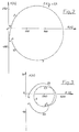
- Travaillant comme une antenne dipôle demie-onde classique et donc à deux brins rayonnants symétriques, comme ces antennes dipôles, les antennes à plan de sol connues à ce jour présentent pour une longueur donnée une variation d'impédance très importante lors de la modification de la fréquence d'utilisation et donc du nombre d'ondes que représente cette longueur (figure 2).
- En effet, pour une variation du nombre d'ondes de onze dixièmes à trente trois dixièmes d'ondes, entre la résistance au rayonnement maximum qui est de sept cent cinquante ohms et la résistance au rayonnement minimum qui est de quinze ohms, le rapport est de cinquante.
- Aussi, avec les antennes connues à ce jour, pour pouvoir couvrir une bande de fréquences de plus d'une octave, il faut :
- - soit, coupler deux dipôles disposés dans le prolongement l'un de l'autre, mais ces antennes dites "colinéaires" sont très encombrantes et peu adaptées à des montages-démontages rapides et fréquents,
- - soit, équiper l'antenne -ou d'une boite d'accord- ou de charges résistives, ce qui, malheureusement, dans le cas de la boîte d'accord, nécessite un cable de télécommande qui est lui-même peu pratique, et, dans le cas, des charges résistives, réduit le rendement de l'antenne.
- Un résultat que l'invention vise à obtenir est une antenne du type cité plus haut, présentant des qualités radioélectriques optimisées dans toute la large bande des fréquences où elle est destinée à fonctionner sans pour autant être encombrante et sans nécessiter ni une boîte d'accord, ni des charges résistives.
- A cet effet, elle a pour objet une telle antenne notamment caractérisée en ce que les contre-poids ont une longueur comprise entre cent quarante et cent quatre vingts pour cent de la longueur du fouet.
- L'invention sera bien comprise à l'aide de la description ci-après faite, à titre d'exemple non limitatif, en regard du dessin ci-annexé qui représente :
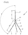
- - figure 1 : une antenne à plan de sol vue de face,
- - figures 2 et 3 : des diagrammes d'impédance.
- En se reportant à la figure 1, on voit que l'antenne 1 comprend un brin rayonnant ou "fouet" 2, ayant une longueur L égale, environ, au quart de la longueur d'onde de la fréquence médiane de la bande utile.
- Sur le support 3 de ce fouet 2 sont montés des brins "contre-poids" 4, 5, 6 qui, afin de constituer un sol artificiel :
- - ont tous une même longueur KL,
- - font tous un même angle avec le fouet au pied duquel ils convergent et,
- - présentent entre eux des écarts angulaires égaux.
- Les contre-poids 4, 5, 6 comme le fouet 2 peuvent être de tout type connu et notamment être démontables et/ou être réalisés en un seul ou plusieurs tronçons 7, 8, 9 de faible longueur pour faciliter le transport.
- A sa ligne de transmission (non représentée), cette antenne 1 est couplée directement ou par l'intermédiaire de tout moyen connu, tel un système 10 transformateur d'impédance dans un rapport déterminé, afin d'adapter l'impédance caractéristique de l'antenne 1 à celle de la dite ligne de transmission ou tel un coupleur large bande (non représenté) de type apte à constituer un réseau présentant un diagramme défini.
- De manière connue, cette antenne travaille comme un dipôle à deux brins rayonnants, l'un réel constitué par le fouet l'autre fictif constitué par son image réfléchie par plan de sol. Aussi, bien que décrire par référence à une antenne à plan de sol, la présente invention trouve également application dans les antennes dipôles à large bande composées de deux brins rayonnants.
- Qu'il soit réel ou fictif, l'un des brins rayonnants de l'antenne a une longueur qui est comprise entre cent quarante et cent quatre vingts pour cent de la longueur de l'autre brin rayonnant.
- Dans l'application aux antennes à contre-poids, ce sont les contre-poids 4, 5, 6 qui ont une longueur KL comprise entre cent quarante et cent quatre vingts pour cent de la longueur du fouet 2 et de préférence, égale à cent soixante pour cent de cette longueur du fouet.
- Par exemple, pour les applications dans les bandes des très hautes fréquences à usages militaires, les fouets et contre-poids auront respectivement mille huit cent et deux mille neuf cent millimètres de long dans l'ancienne bande (vingt six à soixante seize mégahertz) ou de mille six cent et deux mille cinq cent millimètres dans la nouvelle bande (trente à quatre vingt huit mégahertz).
- Au lieu d'être horizontaux, les contre-poids 4, 5, 6 forment chacun avec le fouet 2 un angle de l'ordre de cent trente cinq degrés et sont au nombre de trois.
- Les inventeurs ont en effet constaté qu'avec une telle antenne asymétrique dans de telles proportions, la variation de la résistance au rayonnement est nettement plus faible qu'avec un dipôle symétrique ou une antenne à plan de sol classique dont les contre-poids ont des longueurs égales à celle du fouet.
- En effet, avec cette proportion d'asymétrie entre les brins rayonnants, toujours pour une variation du nombre d'ondes comprise entre onze dixièmes et trente trois dixièmes d'ondes entre la résistance au rayonnement maximum qui est de quatre cents ohms et la résistance au rayonnement minimum qui est de cinquante ohms, le rapport est maintenant de huit au lieu de cinquante.
- Ce résultat démontre que l'antenne asymétrique dans le rapport caractéristique précité est, pour un taux d'ondes stationnaires inférieur à trois, directement adaptée, dans une bande de fréquences de plus d'une octave, à une ligne de transmission d'impédance caractéristique de cent trente cinq ohms.
- A travers le système 10 de transformation d'impédance à large bande, cette antenne peut bien sûr être adaptée à n'importe quelle autre impédance caractéristique de la ligne.
- L'antenne ainsi obtenue peut évidemment être combinée à au moins une autre antenne par un coupleur.
- En résumé, comme caractéristiques radio-électriques optimisées dans la bande de fréquences où elle est destinée à être utilisée, cette antenne présente donc (figure 3) :
- - un taux d'ondes stationnaires inférieur à trois,
- - un diagramme de rayonnement avec un dépointage minimum,
- - un bon découplage avec la ligne de transmission,
- - un rendement élevé.
- Contrairement à ce qu'elle était unanimement considérée par les hommes de l'art, la longueur des contre-poids offre donc une valeur critique.
Claims (7)
Applications Claiming Priority (2)
| Application Number | Priority Date | Filing Date | Title |
|---|---|---|---|
| FR8300736 | 1983-01-13 | ||
| FR8300736A FR2539557B3 (fr) | 1983-01-13 | 1983-01-13 | Antenne a large bande |
Publications (2)
| Publication Number | Publication Date |
|---|---|
| EP0116487A1 true EP0116487A1 (fr) | 1984-08-22 |
| EP0116487B1 EP0116487B1 (fr) | 1988-09-21 |
Family
ID=9285049
Family Applications (1)
| Application Number | Title | Priority Date | Filing Date |
|---|---|---|---|
| EP19840400038 Expired EP0116487B1 (fr) | 1983-01-13 | 1984-01-09 | Antenne à plan de sol |
Country Status (3)
| Country | Link |
|---|---|
| EP (1) | EP0116487B1 (fr) |
| DE (1) | DE3474238D1 (fr) |
| FR (1) | FR2539557B3 (fr) |
Cited By (2)
| Publication number | Priority date | Publication date | Assignee | Title |
|---|---|---|---|---|
| WO1998059390A1 (fr) * | 1997-06-25 | 1998-12-30 | Telefonaktiebolaget Lm Ericsson | Antenne trepied retractable |
| FR2783097A1 (fr) * | 1998-09-04 | 2000-03-10 | Alain Leseine | Antenne d'emission reception d'ondes radio a polarisation verticale a angle d'elevation du lobe de rayonnement variable |
Citations (5)
| Publication number | Priority date | Publication date | Assignee | Title |
|---|---|---|---|---|
| US2124424A (en) * | 1936-01-03 | 1938-07-19 | Gen Electric | Antenna system |
| US2275646A (en) * | 1939-07-18 | 1942-03-10 | Rca Corp | Antenna |
| US2425585A (en) * | 1943-12-13 | 1947-08-12 | Hazeltine Research Inc | Wave-signal antenna |
| US2704811A (en) * | 1950-06-19 | 1955-03-22 | Andrew W Walters | Cylindrical antenna |
| US3656167A (en) * | 1969-11-25 | 1972-04-11 | Plessey Co Ltd | Dipole radio antennae |
-
1983
- 1983-01-13 FR FR8300736A patent/FR2539557B3/fr not_active Expired
-
1984
- 1984-01-09 DE DE8484400038T patent/DE3474238D1/de not_active Expired
- 1984-01-09 EP EP19840400038 patent/EP0116487B1/fr not_active Expired
Patent Citations (5)
| Publication number | Priority date | Publication date | Assignee | Title |
|---|---|---|---|---|
| US2124424A (en) * | 1936-01-03 | 1938-07-19 | Gen Electric | Antenna system |
| US2275646A (en) * | 1939-07-18 | 1942-03-10 | Rca Corp | Antenna |
| US2425585A (en) * | 1943-12-13 | 1947-08-12 | Hazeltine Research Inc | Wave-signal antenna |
| US2704811A (en) * | 1950-06-19 | 1955-03-22 | Andrew W Walters | Cylindrical antenna |
| US3656167A (en) * | 1969-11-25 | 1972-04-11 | Plessey Co Ltd | Dipole radio antennae |
Cited By (3)
| Publication number | Priority date | Publication date | Assignee | Title |
|---|---|---|---|---|
| WO1998059390A1 (fr) * | 1997-06-25 | 1998-12-30 | Telefonaktiebolaget Lm Ericsson | Antenne trepied retractable |
| US6084549A (en) * | 1997-06-25 | 2000-07-04 | Telefonaktiebolaget Lm Ericsson | Retractable tripod antenna |
| FR2783097A1 (fr) * | 1998-09-04 | 2000-03-10 | Alain Leseine | Antenne d'emission reception d'ondes radio a polarisation verticale a angle d'elevation du lobe de rayonnement variable |
Also Published As
| Publication number | Publication date |
|---|---|
| FR2539557B3 (fr) | 1985-12-20 |
| EP0116487B1 (fr) | 1988-09-21 |
| DE3474238D1 (de) | 1988-10-27 |
| FR2539557A1 (fr) | 1984-07-20 |
Similar Documents
| Publication | Publication Date | Title |
|---|---|---|
| CA2821250C (fr) | Antenne d'emission et de reception multifaisceaux a plusieurs sources par faisceau, systeme d'antennes et systeme de telecommunication par satellite comportant une telle antenne | |
| EP0520851A1 (fr) | Antenne mixte pour réception de signaux émis simultanément par satellite et par stations terrestres, notamment pour la réception de signaux de radiodiffusion sonore numérique | |
| FR2845829A1 (fr) | Systeme d'antenne a double reflecteur a foyer en forme d'anneau multi bande | |
| FR2760919A1 (fr) | Systeme de communication par satellite mobile | |
| CA2029378A1 (fr) | Antenne a polarisation circulaire, notamment pour reseau d'antennes | |
| EP0548876B1 (fr) | Antenne active "offset" à double réflecteurs | |
| EP0116487B1 (fr) | Antenne à plan de sol | |
| FR2814285A1 (fr) | Antenne helicoidale a pas variable, et procede correspondant | |
| CA2356725A1 (fr) | Lentille divergente a dome pour ondes hyperfrequences et antenne comportant une telle lentille | |
| EP0934608B1 (fr) | Systeme antennaire pour poste radiotelephone portatif | |
| EP1580837B1 (fr) | Dispositif semi-conducteur à antenne et écran collecteur | |
| FR2641133A1 (fr) | ||
| EP1393411B1 (fr) | Antenne resonante omnidirectionnelle | |
| WO2009077529A2 (fr) | Antenne active tres large bande pour radar passif | |
| EP1339134A1 (fr) | Antenne monopolaire ou dipolaire à large bande | |
| CA2327371C (fr) | Source rayonnante pour antenne d'emission et de reception destinee a etre installee a bord d'un satellite | |
| EP0492022B1 (fr) | Antenne radio électrique à très large bande et à faible taux d'onde stationnaire | |
| EP3155689B1 (fr) | Antenne plate de telecommunication par satellite | |
| FR3013909A1 (fr) | Cornet, antennaire elementaire, structure antennaire et procede de telecommunication associes | |
| FR2634598A1 (fr) | Antenne omnidirectionnelle, notamment pour l'emission de signaux de radiodiffusion ou de television dans la bande des ondes decimetriques, et systeme rayonnant forme d'un groupement de ces antennes | |
| EP0792528B1 (fr) | Antenne de type dip le demi-onde | |
| EP0897200A1 (fr) | Dispositif à antenne demi-boucle haute fréquence | |
| EP0254373A1 (fr) | Antenne pour signaux hautes fréquences | |
| BE676986A (fr) | ||
| FR2609214A1 (fr) | Antenne a large bande, utilisable en ondes metriques |
Legal Events
| Date | Code | Title | Description |
|---|---|---|---|
| PUAI | Public reference made under article 153(3) epc to a published international application that has entered the european phase |
Free format text: ORIGINAL CODE: 0009012 |
|
| AK | Designated contracting states |
Designated state(s): BE CH DE FR GB IT LI LU NL SE |
|
| RIN1 | Information on inventor provided before grant (corrected) |
Inventor name: NGO BUI HUNG, FREDERIC Inventor name: FOISSAC, YVES |
|
| 17P | Request for examination filed |
Effective date: 19850214 |
|
| 17Q | First examination report despatched |
Effective date: 19870626 |
|
| GRAA | (expected) grant |
Free format text: ORIGINAL CODE: 0009210 |
|
| AK | Designated contracting states |
Kind code of ref document: B1 Designated state(s): BE CH DE FR GB IT LI LU NL SE |
|
| PG25 | Lapsed in a contracting state [announced via postgrant information from national office to epo] |
Ref country code: IT Free format text: LAPSE BECAUSE OF FAILURE TO SUBMIT A TRANSLATION OF THE DESCRIPTION OR TO PAY THE FEE WITHIN THE PRESCRIBED TIME-LIMIT;WARNING: LAPSES OF ITALIAN PATENTS WITH EFFECTIVE DATE BEFORE 2007 MAY HAVE OCCURRED AT ANY TIME BEFORE 2007. THE CORRECT EFFECTIVE DATE MAY BE DIFFERENT FROM THE ONE RECORDED. Effective date: 19880921 Ref country code: NL Effective date: 19880921 Ref country code: SE Effective date: 19880921 |
|
| GBT | Gb: translation of ep patent filed (gb section 77(6)(a)/1977) | ||
| REF | Corresponds to: |
Ref document number: 3474238 Country of ref document: DE Date of ref document: 19881027 |
|
| PG25 | Lapsed in a contracting state [announced via postgrant information from national office to epo] |
Ref country code: LU Free format text: LAPSE BECAUSE OF NON-PAYMENT OF DUE FEES Effective date: 19890131 |
|
| NLV1 | Nl: lapsed or annulled due to failure to fulfill the requirements of art. 29p and 29m of the patents act | ||
| PLBE | No opposition filed within time limit |
Free format text: ORIGINAL CODE: 0009261 |
|
| STAA | Information on the status of an ep patent application or granted ep patent |
Free format text: STATUS: NO OPPOSITION FILED WITHIN TIME LIMIT |
|
| 26N | No opposition filed | ||
| PGFP | Annual fee paid to national office [announced via postgrant information from national office to epo] |
Ref country code: BE Payment date: 19980129 Year of fee payment: 15 Ref country code: CH Payment date: 19980129 Year of fee payment: 15 |
|
| PGFP | Annual fee paid to national office [announced via postgrant information from national office to epo] |
Ref country code: FR Payment date: 19990112 Year of fee payment: 16 |
|
| PGFP | Annual fee paid to national office [announced via postgrant information from national office to epo] |
Ref country code: GB Payment date: 19990114 Year of fee payment: 16 |
|
| PGFP | Annual fee paid to national office [announced via postgrant information from national office to epo] |
Ref country code: DE Payment date: 19990116 Year of fee payment: 16 |
|
| PG25 | Lapsed in a contracting state [announced via postgrant information from national office to epo] |
Ref country code: LI Free format text: LAPSE BECAUSE OF NON-PAYMENT OF DUE FEES Effective date: 19990131 Ref country code: BE Free format text: LAPSE BECAUSE OF NON-PAYMENT OF DUE FEES Effective date: 19990131 Ref country code: CH Free format text: LAPSE BECAUSE OF NON-PAYMENT OF DUE FEES Effective date: 19990131 |
|
| BERE | Be: lapsed |
Owner name: LABORATOIRE D'ETUDES ET DE RECHERCHES CHIMIQUES L Effective date: 19990131 |
|
| REG | Reference to a national code |
Ref country code: CH Ref legal event code: PL |
|
| PG25 | Lapsed in a contracting state [announced via postgrant information from national office to epo] |
Ref country code: GB Free format text: LAPSE BECAUSE OF NON-PAYMENT OF DUE FEES Effective date: 20000109 |
|
| GBPC | Gb: european patent ceased through non-payment of renewal fee |
Effective date: 20000109 |
|
| PG25 | Lapsed in a contracting state [announced via postgrant information from national office to epo] |
Ref country code: FR Free format text: LAPSE BECAUSE OF NON-PAYMENT OF DUE FEES Effective date: 20000929 |
|
| PG25 | Lapsed in a contracting state [announced via postgrant information from national office to epo] |
Ref country code: DE Free format text: LAPSE BECAUSE OF NON-PAYMENT OF DUE FEES Effective date: 20001101 |
|
| REG | Reference to a national code |
Ref country code: FR Ref legal event code: ST |
|
| PG25 | Lapsed in a contracting state [announced via postgrant information from national office to epo] |
Ref country code: FR Free format text: LAPSE BECAUSE OF NON-PAYMENT OF DUE FEES Effective date: 19990131 |