EP0116336A2 - Apparatus for receiving and controlling a compensating loop in a continuously fed and intermittently advanced metal strip - Google Patents
Apparatus for receiving and controlling a compensating loop in a continuously fed and intermittently advanced metal strip Download PDFInfo
- Publication number
- EP0116336A2 EP0116336A2 EP84100960A EP84100960A EP0116336A2 EP 0116336 A2 EP0116336 A2 EP 0116336A2 EP 84100960 A EP84100960 A EP 84100960A EP 84100960 A EP84100960 A EP 84100960A EP 0116336 A2 EP0116336 A2 EP 0116336A2
- Authority
- EP
- European Patent Office
- Prior art keywords
- loop
- reel
- strip
- belt
- band
- Prior art date
- Legal status (The legal status is an assumption and is not a legal conclusion. Google has not performed a legal analysis and makes no representation as to the accuracy of the status listed.)
- Withdrawn
Links
Images
Classifications
-
- B—PERFORMING OPERATIONS; TRANSPORTING
- B23—MACHINE TOOLS; METAL-WORKING NOT OTHERWISE PROVIDED FOR
- B23D—PLANING; SLOTTING; SHEARING; BROACHING; SAWING; FILING; SCRAPING; LIKE OPERATIONS FOR WORKING METAL BY REMOVING MATERIAL, NOT OTHERWISE PROVIDED FOR
- B23D33/00—Accessories for shearing machines or shearing devices
- B23D33/02—Arrangements for holding, guiding, and/or feeding work during the operation
-
- B—PERFORMING OPERATIONS; TRANSPORTING
- B21—MECHANICAL METAL-WORKING WITHOUT ESSENTIALLY REMOVING MATERIAL; PUNCHING METAL
- B21C—MANUFACTURE OF METAL SHEETS, WIRE, RODS, TUBES OR PROFILES, OTHERWISE THAN BY ROLLING; AUXILIARY OPERATIONS USED IN CONNECTION WITH METAL-WORKING WITHOUT ESSENTIALLY REMOVING MATERIAL
- B21C49/00—Devices for temporarily accumulating material
-
- B—PERFORMING OPERATIONS; TRANSPORTING
- B65—CONVEYING; PACKING; STORING; HANDLING THIN OR FILAMENTARY MATERIAL
- B65H—HANDLING THIN OR FILAMENTARY MATERIAL, e.g. SHEETS, WEBS, CABLES
- B65H20/00—Advancing webs
- B65H20/24—Advancing webs by looping or like devices
Definitions
- the invention relates to a device for receiving and controlling a compensating loop in a metal strip which is continuously brought up from a strip reel and moved step by step to a strip separating device, the strip reel being wound on a reel; is and the compensating loop forms the transition from the continuously to the gradually moving part of the belt.
- the metal strip is pulled off a strip roll. Because of the cutting process, the so-called cutting to length, it is inevitable that the tape is advanced in time. Such a time consists of two steps, namely a tape advance and the cutting of the tape. Up to three hundred cycles per minute can be run, whereby cycles also occur in which the tape is not advanced but retracted. So that the large mass of the tape reel, whose weight is up to five thousand kilos, is not accelerated and braked again with every cycle a supply and equalization loop is provided. With the feed, the required strip section is gradually withdrawn from the compensation loop, while at the same time the strip is fed into the compensation loop from the strip reel. So this is in the transition from the continuously moving part of the belt to the gradually moving part.
- the loop can vibrate, causing it to jump out of the pit and cause damage.
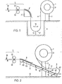
- FIG. 1 A metal strip 4 is unwound from a strip roll 1 which is wound onto a roll reel 2 which stands on a roll stand 3. This unwinding takes place in that the reel 2 is set in rotation by a motor, not shown. The latter maintains the belt's peripheral speed to a value which ensures a reasonably constant replenishment on the belt to a belt cutting device 5.
- This is symbolically represented here by scissors 51 and two feed rollers 52, 53, which move the belt forward in time with the movement of the scissors 51, that is to say stepwise or intermittently. So that this uneven movement cannot affect the tape roll 1, the tape 4 is guided in a compensating loop 6 'to the scissors 51.
- the device according to the invention shown in FIG. 2 provides a remedy here.
- the decisive factor here was the consideration that a compensating loop can no longer swing if it is not hanging freely, but is placed on a surface.
- a loop table 11 is provided for this purpose. This is arranged under the reel 2, somewhat symmetrically to it, ie the two ends 111, 112 of the loops tables must protrude on both sides of the reel 2 for operational reasons.
- the loop table 11 can be mounted horizontally, but it is expedient to have an inclination in the tape running direction of up to 30 °, preferably 22 ° to the horizontal.
- the inlet-side end 111 is lower than the outlet-side end 112, which is located directly in front of the now much shorter inlet segment 7.
- the loop 6 is now placed horizontally on this loop table 11, ie with its outlet-side section 61 which adjoins the lower end 62 of the actual loop bow 63. Only the section 41 of the band 4 located between the band roll 1 and the loop 6 sags freely. However, this section is practically not influenced by the irregularities of the gradual feed by the rollers 52, 53 and therefore does not tend to vibrate.
- the band hold-down device 8 also covers the inlet segment 7, but still projects beyond a section 113 adjoining the outlet-side end 112 of the loop table 11. This ensures good belt guidance and, above all, ensures that differences in belt speeds are only compensated for by the loop 6.
Abstract
Description
Die Erfindung betrifft eine Vorrichtung zur Aufnahme und Steuerung einer Ausgleichsschlaufe in einem kontinuierlich von einer Bandrolle herangeführten und schrittweise zu einer Bandabtrenneinrichtung weiterbewegten Metallband, wobei die Bandrolle auf einem Rollenhaspel aufgewickelt ; ist und die Ausgleichsschlaufe den Uebergang vom kontinuierlich zum schrittweise bewegten Teil des Bandes bildet.The invention relates to a device for receiving and controlling a compensating loop in a metal strip which is continuously brought up from a strip reel and moved step by step to a strip separating device, the strip reel being wound on a reel; is and the compensating loop forms the transition from the continuously to the gradually moving part of the belt.
Zur Herstellung von einzelnen Zuschnitten aus einem Metallband, wie diese z.B. für Transformatoren-Kernbleche verwendet werden, wird das Metallband von einer Bandrolle abgezogen. Hierbei ist es wegen des Abtrennvorgangs, des sogenannten Ablängens, unumgänglich, dass das Band im Takt vorgeschoben wird, Ein solcher Takt besteht aus zwei Schritten, nämlich aus einem Bandvorschub und aus dem Ablängen des Bandes. Es können bis zu dreihundert Takte pro Minute gefahren werden, wobei auch Takte auftreten, in denen das Band nicht vorgeschoben, sondern zurückgezogen wird. Damit die grosse Masse der Bandrolle, deren Gewicht bis zu fünftausend Kilo beträgt, nicht bei jedem Takt beschleunigt und wieder abgebremst werden muss, wird eine Vorrats- und Ausg.leichsschlaufe vorgesehen. Durch den Vorschub wird der jeweils benötigte Bandabschnitt schrittweise von der Ausgleichsschlaufe abgezogen, während gleichzeitig mit einer kontinuierlichen Geschwindigkeit das Band von der Bandrolle her in die Ausgleichsschlaufe nachgeführt wird. Diese befindet sich also im Uebergang vom kontinuierlich bewegten Teil des Bandes zum schrittweise bewegten.To produce individual blanks from a metal strip, such as those used for transformer core sheets, for example, the metal strip is pulled off a strip roll. Because of the cutting process, the so-called cutting to length, it is inevitable that the tape is advanced in time. Such a time consists of two steps, namely a tape advance and the cutting of the tape. Up to three hundred cycles per minute can be run, whereby cycles also occur in which the tape is not advanced but retracted. So that the large mass of the tape reel, whose weight is up to five thousand kilos, is not accelerated and braked again with every cycle a supply and equalization loop is provided. With the feed, the required strip section is gradually withdrawn from the compensation loop, while at the same time the strip is fed into the compensation loop from the strip reel. So this is in the transition from the continuously moving part of the belt to the gradually moving part.
Die bisher verwendeten Vorrichtungen arbeiten mit einer Schlaufe, deren eines Ende von der Bandrolle, das andere, ablaufseitige, von einem der Bandabtrenneinrichtung vorgeschalteten Umklenksegment herunterhängt. Damit für die Bandabtrenneinrichtung jederzeit genügend Vorrat vorhanden ist, muss die Schlaufe möglichst gross gemacht werden. Da jedoch die Bandabtrenneinrichtung nicht beliebig hoch über dem Boden angeordnet werden kann, muss in demselben eine tiefe Grube vorgesehen werden, welche die Schlaufe aufnimmt. Hierbei treten jedoch wesentliche Nachteile auf, vor allem bei hohen Beschleunigungen, Verzögerungen und Geschwindigkeiten des Taktvorschubs, nämlich die folgenden:
- Beim Beschleunigen und Vorschieben des Bandes muss die Masse der Schlaufe ebenfalls beschleunigt und zum Teil angehoben werden, was grössere Beschleunigungskräfte bedingt.
- When accelerating and advancing the belt, the mass of the loop must also be accelerated and partially raised, which requires greater acceleration forces.
Beim Abbremsen schlägt das Band gegen das Umlenksegment oder gegen den auf ihm montierten Bandniederhalter, was zu Beschädigungen am Band führt.When braking, the belt hits against the deflection segment or against the belt retainer mounted on it, which leads to damage to the belt.
Durch die hohen Taktzahlen kann die Schlaufe in Schwingungen geraten, wodurch sie teilweise aus der Grube springen und Beschädigungen verursachen kann.Due to the high number of cycles, the loop can vibrate, causing it to jump out of the pit and cause damage.
Die Kosten zur Erstellung einer Grube sind sehr hoch, und oft fehlt es auch am Platz.The cost of building a pit is very high, and often there is also a lack of space.
Durch das Schwingen der Schlaufe, die Umlenkung beim Umlenksegment und durch das Anschlagen des Bandes gegen das Segment oder gegen den Niederhalter wird die magnetische Leitfähigkeit des Bandes verringert, was bei der Verwendung des Bandes zu Transformatoren-Kernblechen zu grösseren Verlusten im fertigen Transformator führt.By swinging the loop, deflecting the deflecting segment and striking the band against the segment or against the hold-down device, the magnetic conductivity of the band is reduced, which leads to greater losses in the finished transformer when the band is used for transformer core sheets.
Diese Nachteile sollen nun vermieden werden, wofür erfindungsgemäss eine Vorrichtung vorgeschlagen wird, die durch die Merkmale des Anspruchs 1 definiert ist.These disadvantages are now to be avoided, for which a device according to the invention is proposed which is defined by the features of claim 1.
Anhand der beiliegenden Zeichnungen soll die Erfindung in ihren Unterschieden zum Stand der Technik beispielsweise näher erläutert werden; es zeigen in schematischer Darstellung:
- Fig. 1 den genannten Stand der Technik und
- Fig. 2 die erfindungsgemässe Vorrichtung.
- Fig. 1 the prior art and
- Fig. 2 shows the device according to the invention.
Eine der bisher bekannten Vorrichtungen ist in Fig. 1 dargestellt. Von einer Bandrolle 1, die auf einen Rollenhaspel 2 aufgewickelt ist, der auf einem Rollenständer 3 steht, wird ein Metallband 4 abgewickelt. Dieses Abwickeln geschieht dadurch, dass der Rollenhaspel 2 von einem nicht dargestellten Motor in Drehung versetzt wird. Der letztere hält die Umfangsgeschwindigkeit des Bandes auf einem Wert, der einen einigermassen konstanten Nachschub am Band zu einer Bandabtrennvorrichtung 5 gewährleistet. Diese ist hier symbolisch durch eine Schere 51 und zwei Vorschubwalzen 52, 53 dargestellt, welche das Band im Takt der Bewegung der Schere 51 vorwärtsbewegen, also schrittweise oder intermittierend. Damit sich diese ungleichmässige Bewegung nicht auf die Bandrolle 1 auswirken kann, wird das Band 4 in einer Ausgleichsschlaufe 6' zur Schere 51 geführt. Bis jetzt bestand keine andere Möglichkeit, als eine Grube 9 für die Aufnahme dieser Schlaufe 6' vorzusehen, was nicht nur kostspielig war, sondern oft auch noch ein Problem bedeutete, den not- wendigen Raum hierfür vorzusehen, insbesondere in mehrstöckigen Gebäuden. Die Schlaufe muss nämlich genügend gross sein, um den unregelmässigen Vorschub der Walzen 52, 53 auffangen zu können. Dennoch konnte es vorkommen, dass diese Unregelmässigkeiten zu Schwingungen in der Schlaufe führten, wie sie durch den Doppelpfeil 10 angedeutet sind, und dies trotz des relativ grossen Gewichtes G der Schlaufe. Solche Schwingungen, die in ungünstigen Fällen noch durch die Resonanzfrequenz der hängenden Schlaufe verstärkt werden können, führten dazu, dass die Schlaufe gegen die Wände der Grube 9 schlug oder sogar aus der Grube heraussprang, was zu den bereits in der Einleitung aufgeführten Bandschädigungen führte.One of the previously known devices is shown in Fig. 1. A metal strip 4 is unwound from a strip roll 1 which is wound onto a
Die in Fig. 2 dargestellte erfindungsgemässe Vorrichtung schafft hier Abhilfe. Massgebend hierbei war die Ueberlegung, dass eine Ausgleichsschlaufe nicht mehr schwingen kann, wenn sie nicht frei hängend, sondern auf einer Unterlage aufliegend angeordnet ist. Zu diesem Zwecke wird ein Schlaufentisch 11 vorgesehen. Dieser ist unter dem Rollenhaspel 2, einigermassen symetrisch zu diesem, angeordnet, d.h. die beiden Enden 111, 112 des Schlaufentisches müssen aus betrieblichen Gründen beidseitig des Rollenhaspels 2 vorstehen. Der Schlaufentisch 11 kann horizontal angebracht sein, zweckmässig ist jedoch eine Neigung in der Bandlaufrichtung von bis zu 30°, vorzugsweise 22° zur Horizontalen. Hierbei liegt das einlaufseitige Ende 111 tiefer als das ablaufseitige Ende 112, das sich unmittelbar vor dem nun wesentlich kürzeren Einlaufsegment 7 befindet. Auf diesem Schlaufentisch 11 wird nun die Schlaufe 6 liegend abgelegt, d.h. mit ihrem ablaufseitigen Abschnitt 61, der an das untere Ende 62 des eigentlichen Schlaufenbogens 63 angrenzt. Nur noch der zwischen der Bandrolle 1 und der Schlaufe 6 befindliche Abschnitt 41 des Bandes 4 hängt frei durch. Dieser Abschnitt wird aber von den Unregelmässigkeiten des schrittweisen Vorschubs durch die Walzen 52, 53 praktisch nicht beeinflusst und neigt daher auch nicht zum Schwingen.The device according to the invention shown in FIG. 2 provides a remedy here. The decisive factor here was the consideration that a compensating loop can no longer swing if it is not hanging freely, but is placed on a surface. A loop table 11 is provided for this purpose. This is arranged under the
Infolge der Unterschiede im Abrollen des Bandes 4 von der Bandrolle 1 und den durch die Walzen 52, 53 erzeugten Taktvorschub wandert die Schlaufe 6, insbesondere der Schlaufenbogen 62, auf dem Schlaufentisch 11 hin und her. Dieser Bewegungsbereich darf jedoch nicht zu gross werden; so muss vermieden werden, dass einerseits die Schlaufe 6 den Schlaufentisch 11 an seinem einlaufseitigen Ende 111 verlässt und auf dem Boden 12 abrollt, andererseits darf der Schlaufenbogen sich nicht dem Bandniederhalter 8 zu stark nähern. Im weiteren muss auch ein zu starker Durchgang des Bandabschnittes 41 vermieden werden, damit dieser nicht auf dem darunterliegenden, sich über den Schlaufentisch 11 hinwegbewegenden Abschnitt 61 schleift. Zu diesem Zweck sind im Schlaufentisch 11 mehrere Endschalter 13, 14 15, 16 oder jeweils quer verlaufende Reihen von einzelnen Endschaltern vorgesehen, die das Vorhandensein des Bandes registrieren, beispielsweise durch Induktion. Der Schalter 16 bzw. die entsprechende Schalterreihe dient als Sicherheitsendschalter. Die genannten Endschalter wirken wie folgt:
- Bei noch
stillstehender Abtrennvorrichtung 5, aber sichdrehendem Rollenhaspel 2 wird das Band 4 abgerollt und zu einer Schlaufe gebildet. DieseSchlaufe 6 wandert dabei gegen dasEnde 111 des Schlaufentisches zu, bis sie denEndschalter 13 erreicht. Dadurch wird der Motor für den Rollenhaspel ausgeschaltet. Wird nun infolge des Taktvorschubes das Band vorgezogen, bewegt sich die Schlaufe bis zumEndschalter 14. Der Rollenhaspelmotor wird wieder eingeschaltet, und das Band wird von der Bandrolle 1 nachgeführt. Wenn die Nachführung nicht schnell genug erfolgt, wandert dieSchlaufe 6 weiter bis zumEndschalter 15. Dieser bewirkt eine höhere Drehzahl des Rollenhaspels, damit das Band wieder genügend schnell nachgeführt wird. Erreicht aber trotz dieses schnelleren Nachschubes dieSchlaufe 6 denSicherheitsendschalter 16, wird der Antrieb für dieWalzen Schlaufe 6 nicht um das Ende desBandniederhalters 8 herumgespannt wird. In diesem Fall muss die Drehzahl des Rollenhaspels nachgeregelt werden, da offenbar zu wenig Band nachgeführt wird.
- When the
separating device 5 is still stationary, but thereel 2 is rotating, the band 4 is unwound and formed into a loop. Thisloop 6 migrates towards theend 111 of the loop table until it reaches thelimit switch 13. This switches off the motor for the reel. If the tape is now advanced as a result of the clock feed, the loop moves to thelimit switch 14. The reel motor is switched on again and the tape is fed by the tape reel 1. If the tracking does not take place quickly enough, theloop 6 continues to thelimit switch 15. This causes a higher speed of the reel, so that the tape is adjusted sufficiently quickly. However, if theloop 6 reaches thesafety limit switch 16 despite this faster replenishment, the drive for therollers loop 6 is not stretched around the end of the belt hold-downdevice 8. In this case the speed of the reel has to be readjusted, because obviously too little tape is being fed.
Der Bandniederhalter 8 überdeckt auch hier, wie schon bei der Ausführungsform nach Fig. 1, das Einlaufsegment 7, ragt aber noch über einen an das ablaufseitige Ende 112 des Schlaufentisches 11 angrenzenden Abschnitt 113 hinweg. Damit wird eine gute Bandführung erreicht und vor allem auch sichergestellt, dass Unterschiede in den Bandgeschwindigkeiten ausschliesslich durch die Schlaufe 6 ausgeglichen werden.As in the embodiment according to FIG. 1, the band hold-down
Claims (7)
Applications Claiming Priority (2)
| Application Number | Priority Date | Filing Date | Title |
|---|---|---|---|
| CH76483A CH660351A5 (en) | 1983-02-10 | 1983-02-10 | DEVICE FOR RECEIVING AND CONTROLLING A COMPENSATIVE LOOP IN A CONTINUOUSLY PROVIDED AND STEP-BY-STEP METAL STRIP. |
| CH764/83 | 1983-02-10 |
Publications (2)
| Publication Number | Publication Date |
|---|---|
| EP0116336A2 true EP0116336A2 (en) | 1984-08-22 |
| EP0116336A3 EP0116336A3 (en) | 1986-05-14 |
Family
ID=4194626
Family Applications (1)
| Application Number | Title | Priority Date | Filing Date |
|---|---|---|---|
| EP84100960A Withdrawn EP0116336A3 (en) | 1983-02-10 | 1984-01-31 | Apparatus for receiving and controlling a compensating loop in a continuously fed and intermittently advanced metal strip |
Country Status (2)
| Country | Link |
|---|---|
| EP (1) | EP0116336A3 (en) |
| CH (1) | CH660351A5 (en) |
Cited By (5)
| Publication number | Priority date | Publication date | Assignee | Title |
|---|---|---|---|---|
| US4661555A (en) * | 1984-11-28 | 1987-04-28 | Mitsubishi Chemical Industries Limited | Polycarbonate resin composition and process for its production |
| WO1995035253A1 (en) * | 1994-06-22 | 1995-12-28 | M.T. Graphics Pty. Limited | Transfer device for sheet material |
| CN103381454A (en) * | 2013-07-22 | 2013-11-06 | 芜湖市海源铜业有限责任公司 | Manually-adjusting type copper rod collecting device |
| CN103394611A (en) * | 2013-07-22 | 2013-11-20 | 芜湖市海源铜业有限责任公司 | Copper bar collection device |
| CN103662929A (en) * | 2013-12-25 | 2014-03-26 | 大唐微电子技术有限公司 | Strip guide device |
Families Citing this family (2)
| Publication number | Priority date | Publication date | Assignee | Title |
|---|---|---|---|---|
| CN105710437B (en) * | 2016-01-13 | 2018-09-18 | 北京金鹏振兴铜业有限公司 | Sheet metal strip tape divider length adjusting mechanism |
| CN109571036B (en) * | 2019-01-22 | 2021-11-26 | 上海宝钢新材料技术有限公司 | Automatic compensation shearing method based on variable thickness plate arbitrary inflection point identification |
Citations (2)
| Publication number | Priority date | Publication date | Assignee | Title |
|---|---|---|---|---|
| US3857312A (en) * | 1973-09-07 | 1974-12-31 | Cx Corp | Low drag variable demand strip feed |
| US3888400A (en) * | 1974-03-28 | 1975-06-10 | Littell Machine Co F J | Loop control apparatus for continuous strip material |
-
1983
- 1983-02-10 CH CH76483A patent/CH660351A5/en not_active IP Right Cessation
-
1984
- 1984-01-31 EP EP84100960A patent/EP0116336A3/en not_active Withdrawn
Patent Citations (2)
| Publication number | Priority date | Publication date | Assignee | Title |
|---|---|---|---|---|
| US3857312A (en) * | 1973-09-07 | 1974-12-31 | Cx Corp | Low drag variable demand strip feed |
| US3888400A (en) * | 1974-03-28 | 1975-06-10 | Littell Machine Co F J | Loop control apparatus for continuous strip material |
Cited By (5)
| Publication number | Priority date | Publication date | Assignee | Title |
|---|---|---|---|---|
| US4661555A (en) * | 1984-11-28 | 1987-04-28 | Mitsubishi Chemical Industries Limited | Polycarbonate resin composition and process for its production |
| WO1995035253A1 (en) * | 1994-06-22 | 1995-12-28 | M.T. Graphics Pty. Limited | Transfer device for sheet material |
| CN103381454A (en) * | 2013-07-22 | 2013-11-06 | 芜湖市海源铜业有限责任公司 | Manually-adjusting type copper rod collecting device |
| CN103394611A (en) * | 2013-07-22 | 2013-11-20 | 芜湖市海源铜业有限责任公司 | Copper bar collection device |
| CN103662929A (en) * | 2013-12-25 | 2014-03-26 | 大唐微电子技术有限公司 | Strip guide device |
Also Published As
| Publication number | Publication date |
|---|---|
| EP0116336A3 (en) | 1986-05-14 |
| CH660351A5 (en) | 1987-04-15 |
Similar Documents
| Publication | Publication Date | Title |
|---|---|---|
| DE1774704C3 (en) | Device for winding metal coils | |
| DE2156406A1 (en) | Method and device for marking or cutting strip materials | |
| EP0116336A2 (en) | Apparatus for receiving and controlling a compensating loop in a continuously fed and intermittently advanced metal strip | |
| EP0790084A2 (en) | Winding device for bands | |
| DE1627143A1 (en) | Method and device for separating a test piece from a moving belt, in particular a metal belt | |
| DE1276584B (en) | Device for the continuous winding of a flat web of material | |
| DE2049615A1 (en) | Wire winding machine spool changing | |
| EP0620769B1 (en) | Device for slitting strip metal | |
| EP1481930B1 (en) | Winding machine | |
| DE1072080B (en) | Device for changing the direction of movement of running webs made of paper, cardboard, etc. Like. In roll slitting or winding machines or other machines processing running webs | |
| EP0008784B1 (en) | Apparatus for obtaining fast wound coils of equal diameters by coiling several small bands | |
| DE3019929A1 (en) | Winding machine for paper tape, etc. - has intermediate buffer store of tape between supply roll and winding head | |
| DE889734C (en) | Feeding and dispensing device in cold rolling mills for strips with pull-winding drums | |
| DE912712C (en) | Method and machine for the production of high-frequency cables with air space insulation | |
| DE2534198A1 (en) | METHOD AND DEVICE FOR BANDAGING INDUCTION COILS OF LARGE DIAMETERS | |
| DE60119745T2 (en) | APPARATUS AND METHOD FOR TREATING A SHAPE MATERIAL TRACK | |
| DE10248107B4 (en) | Apparatus for cutting sheet-like textile materials | |
| DE602004013164T2 (en) | WINDING DEVICE FOR ROLLERS | |
| DE4300686A1 (en) | Disentangling and possible separate winding up system for linearly cut multi-layer lines | |
| DE2430105A1 (en) | METHOD FOR FEEDING TAPE MATERIAL AT A VERY RAPIDLY CHANGING SPEED AND DEVICE FOR PUSHING THESE TAPES | |
| DE1022542B (en) | Device for guiding the tip of an elevated rolled strip over a loop bed | |
| DE1427812C (en) | Control device for feeding rolled strip in a rolling train | |
| DE977043C (en) | Control of the drive of a machine processing a metal strip | |
| DE1081377B (en) | Mechanical storage mechanism for tape material | |
| DE3508461A1 (en) | Machine for producing curtain strips (feed device) |
Legal Events
| Date | Code | Title | Description |
|---|---|---|---|
| PUAI | Public reference made under article 153(3) epc to a published international application that has entered the european phase |
Free format text: ORIGINAL CODE: 0009012 |
|
| AK | Designated contracting states |
Designated state(s): BE DE FR GB |
|
| PUAL | Search report despatched |
Free format text: ORIGINAL CODE: 0009013 |
|
| AK | Designated contracting states |
Kind code of ref document: A3 Designated state(s): BE DE FR GB |
|
| STAA | Information on the status of an ep patent application or granted ep patent |
Free format text: STATUS: THE APPLICATION IS DEEMED TO BE WITHDRAWN |
|
| 18D | Application deemed to be withdrawn |
Effective date: 19870115 |
|
| RIN1 | Information on inventor provided before grant (corrected) |
Inventor name: SCHNETZER, MAX Inventor name: ANGEHRN, ANTON |