EP0115859B1 - Method and apparatus for controlling windmill blade pitch - Google Patents
Method and apparatus for controlling windmill blade pitch Download PDFInfo
- Publication number
- EP0115859B1 EP0115859B1 EP84101044A EP84101044A EP0115859B1 EP 0115859 B1 EP0115859 B1 EP 0115859B1 EP 84101044 A EP84101044 A EP 84101044A EP 84101044 A EP84101044 A EP 84101044A EP 0115859 B1 EP0115859 B1 EP 0115859B1
- Authority
- EP
- European Patent Office
- Prior art keywords
- pitch
- control
- output
- speed
- blade
- Prior art date
- Legal status (The legal status is an assumption and is not a legal conclusion. Google has not performed a legal analysis and makes no representation as to the accuracy of the status listed.)
- Expired
Links
- 238000000034 method Methods 0.000 title claims description 10
- 230000008859 change Effects 0.000 claims description 14
- 230000004044 response Effects 0.000 claims description 7
- 238000012935 Averaging Methods 0.000 claims 2
- 239000011295 pitch Substances 0.000 description 66
- 230000001133 acceleration Effects 0.000 description 11
- 230000007423 decrease Effects 0.000 description 9
- 230000006870 function Effects 0.000 description 7
- 230000009471 action Effects 0.000 description 6
- 238000010248 power generation Methods 0.000 description 6
- 238000013459 approach Methods 0.000 description 5
- 238000010586 diagram Methods 0.000 description 5
- 230000008901 benefit Effects 0.000 description 3
- 230000006698 induction Effects 0.000 description 3
- 238000004364 calculation method Methods 0.000 description 2
- 230000001419 dependent effect Effects 0.000 description 2
- 230000000694 effects Effects 0.000 description 2
- 230000007246 mechanism Effects 0.000 description 2
- 230000002028 premature Effects 0.000 description 2
- 238000005070 sampling Methods 0.000 description 2
- 230000001360 synchronised effect Effects 0.000 description 2
- 230000003044 adaptive effect Effects 0.000 description 1
- 230000003247 decreasing effect Effects 0.000 description 1
- 230000001934 delay Effects 0.000 description 1
- 238000009434 installation Methods 0.000 description 1
- 230000010354 integration Effects 0.000 description 1
- 230000007774 longterm Effects 0.000 description 1
- 238000013178 mathematical model Methods 0.000 description 1
- 238000012544 monitoring process Methods 0.000 description 1
- 230000000737 periodic effect Effects 0.000 description 1
- 230000008569 process Effects 0.000 description 1
- 238000005086 pumping Methods 0.000 description 1
- 230000009467 reduction Effects 0.000 description 1
- 230000002441 reversible effect Effects 0.000 description 1
- 230000000630 rising effect Effects 0.000 description 1
- 238000005204 segregation Methods 0.000 description 1
- XLYOFNOQVPJJNP-UHFFFAOYSA-N water Substances O XLYOFNOQVPJJNP-UHFFFAOYSA-N 0.000 description 1
Images

Classifications
-
- F—MECHANICAL ENGINEERING; LIGHTING; HEATING; WEAPONS; BLASTING
- F03—MACHINES OR ENGINES FOR LIQUIDS; WIND, SPRING, OR WEIGHT MOTORS; PRODUCING MECHANICAL POWER OR A REACTIVE PROPULSIVE THRUST, NOT OTHERWISE PROVIDED FOR
- F03D—WIND MOTORS
- F03D7/00—Controlling wind motors
- F03D7/02—Controlling wind motors the wind motors having rotation axis substantially parallel to the air flow entering the rotor
- F03D7/04—Automatic control; Regulation
- F03D7/042—Automatic control; Regulation by means of an electrical or electronic controller
- F03D7/043—Automatic control; Regulation by means of an electrical or electronic controller characterised by the type of control logic
-
- F—MECHANICAL ENGINEERING; LIGHTING; HEATING; WEAPONS; BLASTING
- F03—MACHINES OR ENGINES FOR LIQUIDS; WIND, SPRING, OR WEIGHT MOTORS; PRODUCING MECHANICAL POWER OR A REACTIVE PROPULSIVE THRUST, NOT OTHERWISE PROVIDED FOR
- F03D—WIND MOTORS
- F03D7/00—Controlling wind motors
- F03D7/02—Controlling wind motors the wind motors having rotation axis substantially parallel to the air flow entering the rotor
- F03D7/022—Adjusting aerodynamic properties of the blades
- F03D7/0224—Adjusting blade pitch
-
- F—MECHANICAL ENGINEERING; LIGHTING; HEATING; WEAPONS; BLASTING
- F05—INDEXING SCHEMES RELATING TO ENGINES OR PUMPS IN VARIOUS SUBCLASSES OF CLASSES F01-F04
- F05B—INDEXING SCHEME RELATING TO WIND, SPRING, WEIGHT, INERTIA OR LIKE MOTORS, TO MACHINES OR ENGINES FOR LIQUIDS COVERED BY SUBCLASSES F03B, F03D AND F03G
- F05B2270/00—Control
- F05B2270/10—Purpose of the control system
- F05B2270/101—Purpose of the control system to control rotational speed (n)
-
- F—MECHANICAL ENGINEERING; LIGHTING; HEATING; WEAPONS; BLASTING
- F05—INDEXING SCHEMES RELATING TO ENGINES OR PUMPS IN VARIOUS SUBCLASSES OF CLASSES F01-F04
- F05B—INDEXING SCHEME RELATING TO WIND, SPRING, WEIGHT, INERTIA OR LIKE MOTORS, TO MACHINES OR ENGINES FOR LIQUIDS COVERED BY SUBCLASSES F03B, F03D AND F03G
- F05B2270/00—Control
- F05B2270/10—Purpose of the control system
- F05B2270/20—Purpose of the control system to optimise the performance of a machine
-
- F—MECHANICAL ENGINEERING; LIGHTING; HEATING; WEAPONS; BLASTING
- F05—INDEXING SCHEMES RELATING TO ENGINES OR PUMPS IN VARIOUS SUBCLASSES OF CLASSES F01-F04
- F05B—INDEXING SCHEME RELATING TO WIND, SPRING, WEIGHT, INERTIA OR LIKE MOTORS, TO MACHINES OR ENGINES FOR LIQUIDS COVERED BY SUBCLASSES F03B, F03D AND F03G
- F05B2270/00—Control
- F05B2270/30—Control parameters, e.g. input parameters
- F05B2270/327—Rotor or generator speeds
-
- F—MECHANICAL ENGINEERING; LIGHTING; HEATING; WEAPONS; BLASTING
- F05—INDEXING SCHEMES RELATING TO ENGINES OR PUMPS IN VARIOUS SUBCLASSES OF CLASSES F01-F04
- F05B—INDEXING SCHEME RELATING TO WIND, SPRING, WEIGHT, INERTIA OR LIKE MOTORS, TO MACHINES OR ENGINES FOR LIQUIDS COVERED BY SUBCLASSES F03B, F03D AND F03G
- F05B2270/00—Control
- F05B2270/30—Control parameters, e.g. input parameters
- F05B2270/328—Blade pitch angle
-
- Y—GENERAL TAGGING OF NEW TECHNOLOGICAL DEVELOPMENTS; GENERAL TAGGING OF CROSS-SECTIONAL TECHNOLOGIES SPANNING OVER SEVERAL SECTIONS OF THE IPC; TECHNICAL SUBJECTS COVERED BY FORMER USPC CROSS-REFERENCE ART COLLECTIONS [XRACs] AND DIGESTS
- Y02—TECHNOLOGIES OR APPLICATIONS FOR MITIGATION OR ADAPTATION AGAINST CLIMATE CHANGE
- Y02E—REDUCTION OF GREENHOUSE GAS [GHG] EMISSIONS, RELATED TO ENERGY GENERATION, TRANSMISSION OR DISTRIBUTION
- Y02E10/00—Energy generation through renewable energy sources
- Y02E10/70—Wind energy
- Y02E10/72—Wind turbines with rotation axis in wind direction
Definitions
- the present invention relates to windmill control, and it is concerned particularly with control of the pitch angle of the windmill's turbine blades during operation.
- windmill-driven generator increases with wind speed, and so does the wind force experienced by the windmill. High wind speeds can cause the generator to exceed its rated power level and thus damage the generator. Other windmill parts are also subject to damage or excessive fatigue when the wind force is too high. This is true not only of windmills used for power generation but also of windmills used, for example, to pump water. So there must be some way to control the wind force experienced by the windmill. One way is to control blade pitch.
- the speed of windmill rotation must be at least great enough to provide some "slip" between the generator rotation and the phase advance of the voltage on the power grid. As the speed increases, so does the power generation, but excessive speed can overheat the generator or mechanically strain the windmill, causing damage or premature wear. Too little speed, on the other hand, results in inefficient use of the system. Therefore, it is important to control the speed of the turbine by adjusting the pitch of its blades.
- a speed sensor generates a speed signal
- a control circuit that receives the speed signal determines whether the speed is outside of a relatively wide deadband. If it is, then the control circuit commands a blade-pitch actuator mechanism to adjust the blade pitch accordingly. If the current speed as sensed by the speed sensor is not outside the wide deadband, the control circuit then determines whether the average turbine speed over a predetermined interval is outside a narrower deadband that is within the wider deadband. If it is not, then again no control action is taken. If it is, the control circuit causes the blade-pitch actuator to adjust the blade pitch appropriately.
- the same principle can also be applied when control outputs other than speed are sensed.
- control circuit determines the actuator drive time required to effect enough pitch-angle change to correct a power deviation.
- the drive time is determined as a function of turbine speed error.
- the control system can also include a pitch-angle sensor and can determine the drive time as a function of pitch angle as well.
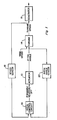
- Fig. 1 is a block diagram depicting the general form of a control system for controlling the turbine speed of a windmill used for electric power generation.
- a pitch-control circuit 10 to be described in more detail below generates command signals and applies them to an actuator 12, which adjusts the pitch angle of the blades of the windmill turbine 14.
- an increased pitch results in a decreased speed of the turbine 14 for a given wind speed, while a reduction in blade pitch results in a higher turbine speed.
- the pitch-control circuit 10 thereby controls turbine speed, and thus the speed of generator 16 driven by the turbine, by varying the pitch angle of the turbine blades.
- the actuator 12 may be of the type illustrated in more detail in WO ⁇ A ⁇ 83/00195 having a priority date July 13, 1981, by Allan Chertok, et al. for "Windpower System".
- the actuator of the Chertok application includes a servomotor for rotating an actuating nut that threadedly engages an actuating rod.
- the rod is mounted in the interior of the turbine shaft to rotate with the turbine shaft but slide axially along it.
- the actuating rod moves axially if there is relative rotation between the nut and the turbine shaft.
- the actuating rod is linked to the blades to cause a pitch change when it moves axially.
- a clutch keeps the actuating nut rotating at the same speed as the shaft and rod, so the pitch of the turbine blades remains constant.
- the clutch is disengaged, and the servomotor rotates the nut in one direction or the other relative to the turbine rotation to increase or decrease the pitch of the turbine blades.
- the servomotor is commanded only to run in two states, forward and reverse; the speed of the servomotor is not dependent on pitch angle, and the duration of its operation depends only on initial pitch angle and turbine speed, not on changes in these variables that occur during servomotor operation.
- the pitch-control circuit is preferably a microprocessor-based circuit that keeps track of the rotational speed of the turbine by means of a speed sensor.
- the speed sensor includes a tachometer that generates pulses at a frequency proportional to the rotational speed of the turbine shaft. It also includes a counter for counting these pulses. The number of pulses counted in a given time interval is thus proportional to the speed of the turbine.
- the control system also includes a pitch-angle transducer that provides signals representing the current pitch angle of the turbine blades.
- a pitch-angle sensor includes a potentiometer operated by the turbine-blade actuating rod. The potentiometer output is applied to a voltage- controlled oscillator whose frequency is thereby a measure of the blade angle. Specifically, the number of oscillator output pulses generated during a given interval is an indication of the pitch angle.
- Control of turbine speed in accordance with the broader teachings of the present invention can be accomplished without the use of the pitch-angle sensor; it is possible to sense only turbine speed and to increase or decrease the blade pitch if the speed is too high or too low, respectively.
- the information derived from the pitch-angle sensor is instrumental in achieving efficient control of turbine speed.
- the invention is concerned mainly with the control methods used for the range of turbine speeds and pitch angles that result when the wind speed is high enough to drive the turbine at an optimum rotational speed for which the system has been designed.
- the control of blade pitch is carried out in a manner different from that which will be described below, specifically in a manner described in WO-A-83/00195.
- the pitch-control circuit determines whether or not to apply command signals to the actuator by comparing the current turbine speed with a wide speed deadband that brackets a predetermined optimum speed and also by comparing the average speed over a predetermined interval with a narrower deadband.
- the control system keeps the average speed of the turbine within narrow limits that provide maximum output power while avoiding premature fatigue failure; it ignores short-term excursions outside this range unless they are so large as to be potentially damaging or to cause unacceptable drops in efficiency.
- the effective bandwidth of the system is narrow when it is dealing with small excursions but wider when large excursions occur.
- the control system is thus a dual-bandwidth/dual-deadband system.
- the dual-deadband scheme is illustrated in Fig. 2, in which the deadbands are plotted on a slip-speed axis.
- the slip speed is the difference between the turbine speed and the speed at which the turbine would be rotating if it were driving the generator in synchronism with the gridireage-i.e., it is the difference between the turbine speed and the speed at which the generator neither generates power nor receives power from the power grid.
- the speed designated as optimum in Fig. 2 is the speed at which the generator generates as high a power as is possible without excessive system strain.
- the narrow deadband 21a is the region to which the pitch-control circuit 10 keeps the average turbine speed, while the wide deadband 21 b is the range of current-speed values that the pitch-control circuit will allow.
- Those speeds between the upper ends of the two deadbands are the speeds that would cause excessive wear to the system if they were allowed to continue over long periods, but they are relatively inconsequential if they occur only for short durations.
- the speeds between the lower ends of the two deadbands represent power outputs that are too low to be tolerated on a long-term basis but not so low as to require operating the blade-pitch actuator while the average speed is within the narrow deadband.
- the upper end of the wider deadband is the beginning of a speed region in which the danger of damage to the system becomes significant, even for short-term excursions. It is thus important to adjust the speed of the turbine promptly whenever this region is reached.
- the lower end of the wide deadband can be set in consideration of various factors. It will typically be a value that is reached infrequently enough so that undue wear to the control system is not caused by driving the system back to the optimum speed whenever this limit is reached. That is, this value will typically represent a compromise between power-generation efficiency and control-system wear.
- the actuator After the decision is made to call for action from the actuator, the actuator is operated in a way that further contributes to the efficiency of the system.
- the system typically includes considerable lags, both in detecting power deviations and in effecting corrective pitch changes. These result from the moment of inertia of the turbine and from delays in the control system. Therefore, it would not be effective merely to keep changing the blade pitch until the proper speed is sensed. If the controller has much gain, it would be difficult to avoid overshooting the desired speed. On the other hand, more-sluggish control detracts from efficiency and, in addition, can prevent prompt response to potentially damaging wind gusts.
- the pitch-control circuit 10 of the present invention turns on the actuator 12 for a time that is a predetermined function of turbine-speed error and initial blade pitch. More specifically, when the pitch-control circuit 10 determines that it is necessary to command the servomotor of the actuator 12 to rotate the actuating nut that adjusts the turbine pitch, it determines an optimum drive time for the servomotor that is a function of the present pitch angle and either the current or average turbine speed. The duration of servomotor actuation is then set; it is not dependent on values of system variables sensed later, while the actuator is operating.
- Fig. 3 is a phase-plane plot whose axes represent slip speed and its first derivative, turbine acceleration.
- the starting point of the plot reflects the assumption that the slip speed is relatively constant at the beginning of the control operation-i.e., that turbine acceleration is zero-and there is a further assumption that wind speed is constant during servomotor operation and the resultant approach of the turbine speed to its optimum value subsequent settling.
- the phase-plane plot also indicates the advisability of having a rest interval after the removal of the command signal from the servomotor so that samplings of slip speed taken during this interval are not relied upon as current speed values for determining whether or not to command another actuator operation.
- Fig. 3 for instance, an error remains for a time after the servo drive is removed, but the slip speed asymptotically approaches the optimum speed without any further control. Sampling during this period, with resultant servomotor operation, would drive the slip speed beyond the optimum.
- the programming of the pitch-control circuit includes a provision for a rest time during which the application of control signals is inhibited.
- the servomotor drive time will in general be different for different initial errors. This is illustrated in Fig. 4, which shows differing initial errors and the optimum control trajectories that might result.
- Plot 22 represents a relatively large error as an initial condition, while plots 24 and 26 represent intermediate and smaller initial errors, respectively.
- Each plot includes its respective servomotor turn-off point 28, 30, or 32, and it is apparent after a little reflection that the time taken to reach the servomotor off point 32 is less than that required to reach servomotor off point 28; if the error is less, it takes less time to correct it.
- Fig. 4 also shows a further trajectory 34.
- This is an example of a trajectory for an initial slip speed that is higher than the optimum.
- the shape of the curve differs somewhat from the general shapes of the other curves because the pitch servosystem can reduce blade pitch faster than it can increase it, but the same result is apparent: the servomotor drive time depends on the initial error.
- Fig. 5 illustrates that the servomotor drive times differ for different values of initial pitch angle, too. This is because the control effectiveness of pitch varies with pitch angle. More specifically, the first partial derivative of slip speed with respect to pitch angle is a function of pitch angle. In other words, the pitch-angle change required to achieve a given slip-speed change varies with the initial value of the pitch angle.
- Plots 38, 40 and 42 of Fig. 5 represent different optimum trajectories for which the initial speed errors are the same but the initial angles are different. Like Figs. 3 and 4, Fig. 5 illustrates general characteristics; it is not intended to be quantitatively accurate.
- Plot 38 represents an initial pitch angle at which control effectiveness is high; i.e., the slip-speed change for a given change in blade pitch is relatively high. As a consequence, the pitch-change drive time represented by trajectory 38 is relatively short.
- Trajectory 40 represents an intermediate value of control effectiveness and thus an intermediate value of drive time to achieve the optimum speed, while the low control effectiveness represented by trajectory 42 results in a more gradual approach to the optimum speed. Accordingly, the turn-off times 44, 46, and 48 for trajectories 38, 40 and 42 are reached at different time intervals after the servomotor is turned on.
- the pitch-control circuit includes a look-up table organized according to slip-speed error and blade pitch. It contains entries of servomotor drive time. When it is determined that control action must be taken, the drive-time entry is fetched from the location specified by the pitch angle and the current or average slip-speed error, and the actuator is operated accordingly.
- the look-up-table entries can be determined experimentally or by resort to a mathematical model of the system.
- the entries can be determined adaptively by the pitch-control circuit 10 in accordance with experience so that changes due to wear, age, and other factors can be accommodated. No such adaptive arrangement is illustrated here, but the entries are stored in a protected portion of a read-write memory so that they can be rewritten from an external source if changes appears necessary.
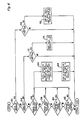
- FIG. 6 A simplified flow chart illustrating the control routine performed by the pitch-control circuit 10 is depicted in Fig. 6.
- the various functions depicted in Fig. 6 are arranged for ease of description, and they do not slavishly follow the segregation into executive program and subroutines that practical considerations might dictate.
- the pitch control circuit 10 is based on an executive program that services two groups of routines.
- the first group supervises sensors, frequency-measuring counters, and control timers. This group is serviced whenever a real-time clock included in the system interrupts the processor. The interrupt interval is long enough to insure that this group of routines is completed well before the next interrupt. The remaining time is used to service a second group of routines.
- One of these is a control routine, and it is illustrated in Fig. 6. It uses sensor-input and timer-status data reported by the routines of the first group.
- the processor Upon entry into the control routine, the processor initially determines whether the actuator 12 is currently in the process of driving the turbine blades to a different pitch angle. This determination is represented in Fig. 6 by a decision block 52. If no drive is in progress, the routine checks to see if the system is still in a rest period after the last actuation, as block 54 indicates. If not, the current speed is tested, as blocks 56 and. 58 indicate, to determine whether it is outside the wide deadband. if not, the average speed is checked, as blocks 60 and 62 indicate. If neither the current nor the average speed is outside its designated deadband, the control routine returns control to the executive program.
- control routine If, the current or average speed is outside its limits, on the other hand, the control routine consults its look-up table, as block 64 indicates, to find the value of servomotor drive time dictated by the initial pitch angle and either the current- or the average-speed error. The control routine then proceeds to the steps represented by block 66; it turns on the servomotor, sets a drive timer with the drive-time value fetched in the step represented by block 64, and sets a "drive in progress" flag, which is the flag tested during the step represented by block 52. The control routine then returns control to the executive program.
- the test represented by block 52 finds that the "drive in progress" flag is set. Accordingly, the routine branches to a test represented in Fig. 6 by block 68. In this test, the processor checks to determine whether the drive timer, which was set in the step represented by block 66, has timed out. If it has not, control is returned to the executive program. If it has, the microprocessor turns off the actuator 12, as block 70 indicates, and it sets a hold timer, which begins to time the rest period that must be observed after servomotor actuation terminates. A "hold in progress" flag is then set, and the routine returns control to the executive program.
- the test represented by block 52 indicates that a drive is no longer in progress, so the routine checks the "hold in progress" flag that was set in the step represented by block 70. It finds that this flag has been set, so it checks to see whether the hold timer has timed out. This test is represented in Fig. 6 by decision block 72. During the first pass through the control routine after the "hold in progress" flag has been set, the hold timer typically has not timed out, and the control routine returns control to the executive program. On some subsequent pass through the routine, however, the rest time will have ended, and the test represented by block 72 will result in an affirmative determination. When it does, the routine resets the "hold in progress" flag, as block 74 indicates, and returns control to the executive program. The system is then ready to test the current or average speed when the control routine is next called.
- the times represented by the look-up-table values can be adjusted under program control in accordance with experience.
- the look-up-table values can represent blade-pitch changes that are fixed for given initial conditions, but the servomotor drive times employed to achieve the pitch change can be varied based on previous observations of the response of blade pitch to servomotor operation.
- a routine would turn on the servomotor until the desired pitch change is indicated by the pitch sensor.
- such a system might turn off the drive somewhat before the desired position is detected to allow for turn-off lag and coasting.
- deadband limits can be set adaptively.
- the program may keep track of how many excursions of average or current speed outside their respective deadbands occur within a predetermined period, and if there have been no such excursions or very few, the deadband widths can be tightened to increase generator productivity without significantly increasing the number of actuator operations.
- a formula can be included in the program, or the look-up table can be expanded, to include the value of the initial turbine acceleration in the calculation of the drive time or rest time.
- the "optimum speed" can be set adaptively. For example, it might be desirable to fix the value of the upper wide-deadband limit and adjust the optimum speed based on the frequency with which the upper wide-deadband limit is exceeded. One way of doing this is to increase the optimum speed periodically but decrease it whenever the upper wide-deadband limit is exceeded. Such an arrangement would lower the target for the average speed during gusty conditions and thus keep the frequency of high-power excursions within acceptable bounds.
- the teachings of the present invention can be used in simpler control systems, also.
- the value of initial blade pitch can be left out of the drive-time calculations.
- Such a system would control in a less efficient fashion, of course, but it would still have the basic benefit of the invention, namely, that of responding promptly to wide excursions of turbine speed but avoiding excessive control actuations by keeping only the average speed within the tighter deadband limits.
- control output monitored in the illustrated embodiment is slip speed
- the broader teachings of the present invention can also be employed by monitoring other control outputs.
- the output ultimately of interest is power, and this is sensed indirectly as turbine speed.
- power can be sensed by sensing the torque output of the windmill.
- output power is roughly proportional to output torque because the slip speed of an induction generator typically is not much more than 2% of the synchronous speed. If the teachings of the present invention were employed in a system for driving a synchronous generator rather than an induction generator, the use of output torque as the sensed variable would be particularly appropriate, since turbine speed would not be an indication of output power. Sensing of the phase difference between the generator and the power grid can also be used in synchronous-generator installations. In the alternative, output power can be measured directly by electric-power sensors.
- the teachings of the present invention are not restricted to windmills used for electric power generation.
- the output of interest might still be power-in this case, mechanical power-but output speed or torque may also be the variables of interest.
- the basic teachings of the present invention remain the same. That is, the average control output is caused to remain within a narrow deadband, but the current control output is only required to stay within a wider deadband.
- teachings of the present invention can be followed in a wide range of control systems to achieve a high level of windmill productivity with a relatively low frequency of actuator operation.
Landscapes
- Engineering & Computer Science (AREA)
- Life Sciences & Earth Sciences (AREA)
- Sustainable Development (AREA)
- Sustainable Energy (AREA)
- Chemical & Material Sciences (AREA)
- Combustion & Propulsion (AREA)
- Mechanical Engineering (AREA)
- General Engineering & Computer Science (AREA)
- Physics & Mathematics (AREA)
- Fluid Mechanics (AREA)
- Wind Motors (AREA)
Applications Claiming Priority (2)
| Application Number | Priority Date | Filing Date | Title |
|---|---|---|---|
| US464726 | 1983-02-07 | ||
| US06/464,726 US4426192A (en) | 1983-02-07 | 1983-02-07 | Method and apparatus for controlling windmill blade pitch |
Publications (2)
| Publication Number | Publication Date |
|---|---|
| EP0115859A1 EP0115859A1 (en) | 1984-08-15 |
| EP0115859B1 true EP0115859B1 (en) | 1988-05-11 |
Family
ID=23845003
Family Applications (1)
| Application Number | Title | Priority Date | Filing Date |
|---|---|---|---|
| EP84101044A Expired EP0115859B1 (en) | 1983-02-07 | 1984-02-02 | Method and apparatus for controlling windmill blade pitch |
Country Status (5)
| Country | Link |
|---|---|
| US (1) | US4426192A (ja) |
| EP (1) | EP0115859B1 (ja) |
| JP (1) | JPS59188073A (ja) |
| CA (1) | CA1214848A (ja) |
| DE (1) | DE3471136D1 (ja) |
Cited By (1)
| Publication number | Priority date | Publication date | Assignee | Title |
|---|---|---|---|---|
| US20240026857A1 (en) * | 2018-06-08 | 2024-01-25 | Wobben Properties Gmbh | Method for operating a wind turbine, wind turbine, and wind park |
Families Citing this family (42)
| Publication number | Priority date | Publication date | Assignee | Title |
|---|---|---|---|---|
| US4426192A (en) * | 1983-02-07 | 1984-01-17 | U.S. Windpower, Inc. | Method and apparatus for controlling windmill blade pitch |
| DE3566015D1 (en) * | 1984-03-26 | 1988-12-08 | Alfred Jurisch | Windmill-driven generator |
| JPS61164042A (ja) * | 1985-01-16 | 1986-07-24 | Nissan Motor Co Ltd | タ−ボチヤ−ジヤの過給圧制御装置 |
| US5083039B1 (en) * | 1991-02-01 | 1999-11-16 | Zond Energy Systems Inc | Variable speed wind turbine |
| US5155375A (en) * | 1991-09-19 | 1992-10-13 | U.S. Windpower, Inc. | Speed control system for a variable speed wind turbine |
| US6177735B1 (en) | 1996-10-30 | 2001-01-23 | Jamie C. Chapman | Integrated rotor-generator |
| US6600240B2 (en) * | 1997-08-08 | 2003-07-29 | General Electric Company | Variable speed wind turbine generator |
| CN1426510A (zh) * | 2000-03-08 | 2003-06-25 | 里索国家实验室 | 一种操作涡轮机的方法 |
| AU2001274396A1 (en) * | 2000-05-23 | 2001-12-03 | Vestas Wind Systems A/S | Variable speed wind turbine having a matrix converter |
| DE10058076C2 (de) | 2000-11-23 | 2003-06-12 | Aloys Wobben | Verfahren zur Steuerung einer Windenergieanlage |
| DE10106208C2 (de) * | 2001-02-10 | 2002-12-19 | Aloys Wobben | Windenergieanlage |
| US7071578B1 (en) * | 2002-01-10 | 2006-07-04 | Mitsubishi Heavy Industries, Ltd. | Wind turbine provided with a controller for adjusting active annular plane area and the operating method thereof |
| US7015595B2 (en) * | 2002-02-11 | 2006-03-21 | Vestas Wind Systems A/S | Variable speed wind turbine having a passive grid side rectifier with scalar power control and dependent pitch control |
| DE10338127C5 (de) * | 2003-08-15 | 2015-08-06 | Senvion Se | Windenergieanlage mit einem Rotor |
| US8649911B2 (en) * | 2005-06-03 | 2014-02-11 | General Electric Company | System and method for operating a wind farm under high wind speed conditions |
| US7351033B2 (en) * | 2005-09-09 | 2008-04-01 | Mcnerney Gerald | Wind turbine load control method |
| DK176552B1 (da) * | 2005-12-29 | 2008-08-04 | Lm Glasfiber As | Variabelt speed nav |
| CN101401294B (zh) * | 2006-03-17 | 2013-04-17 | 英捷电力技术有限公司 | 具有激励器设备和不连接至电网的功率变换器的变速风机 |
| US7425771B2 (en) * | 2006-03-17 | 2008-09-16 | Ingeteam S.A. | Variable speed wind turbine having an exciter machine and a power converter not connected to the grid |
| ES2288121B1 (es) * | 2006-05-31 | 2008-10-16 | GAMESA INNOVATION & TECHNOLOGY, S.L. | Metodo de operacion de un aerogenerador. |
| DE102006040970B4 (de) * | 2006-08-19 | 2009-01-22 | Nordex Energy Gmbh | Verfahren zum Betrieb einer Windenergieanlage |
| DE102007006966A1 (de) * | 2007-02-13 | 2008-08-14 | Robert Bosch Gmbh | Antriebseinrichtung zum Antreiben von mehreren Achsen |
| WO2009010061A2 (en) * | 2007-07-14 | 2009-01-22 | Vestas Wind Systems A/S | A wind turbine, a method for compensating for disparities in a wind turbine rotor blade pitch system and use of a method. |
| CN101878365B (zh) * | 2007-11-30 | 2012-06-27 | 维斯塔斯风力系统有限公司 | 风力涡轮机、控制风力涡轮机的方法及其用途 |
| WO2009068036A2 (en) * | 2007-11-30 | 2009-06-04 | Vestas Wind Systems A/S | A wind turbine, a method for controlling a wind turbine and use thereof |
| US8038395B2 (en) * | 2008-03-28 | 2011-10-18 | General Electric Company | Pulsed torque control of wind turbine pitch systems |
| GB0816637D0 (en) * | 2008-09-12 | 2008-10-22 | Rolls Royce Plc | Blade Pitch Control |
| US8712593B2 (en) * | 2008-11-18 | 2014-04-29 | Vestas Wind Systems A/S | Method for controlling operation of a wind turbine |
| US8274169B2 (en) * | 2008-11-25 | 2012-09-25 | Schopf William K | Wind powered generator for a vehicle |
| US10435145B1 (en) | 2009-07-02 | 2019-10-08 | Alfred Finnell | Vehicle with tension wing assembly |
| US10443569B1 (en) * | 2009-07-02 | 2019-10-15 | Alfred Finnell | Wind or water based power generating system |
| US11021243B1 (en) | 2009-07-02 | 2021-06-01 | Alfred Finnell | Tension airfoil assembly and implementation for power generation and aviation |
| US7750490B2 (en) * | 2009-08-28 | 2010-07-06 | General Electric Company | Method and system for extracting inertial energy from a wind turbine |
| US8227929B2 (en) * | 2009-09-25 | 2012-07-24 | General Electric Company | Multi-use energy storage for renewable sources |
| US7755210B2 (en) * | 2009-12-04 | 2010-07-13 | General Electric Company | System and method for controlling wind turbine actuation |
| DK177434B1 (en) * | 2010-06-18 | 2013-05-21 | Vestas Wind Sys As | Method for controlling a wind turbine |
| DE102011105854B4 (de) * | 2011-06-03 | 2013-04-11 | Nordex Energy Gmbh | Verfahren zum Betreiben einer Windenergieanlage bei Auftreten eines Netzfehlers sowie eine solche Windenergieanlage |
| US9518560B2 (en) * | 2013-05-28 | 2016-12-13 | Siemens Aktiengesellschaft | Method to individually optimize respective pitch angles of a plurality of blades in a wind turbine |
| US9784241B2 (en) * | 2014-08-25 | 2017-10-10 | General Electric Company | System and method for controlling a wind turbine |
| DK3051124T3 (en) | 2015-01-30 | 2018-10-15 | Adwen Gmbh | Procedure for operating a wind turbine without mains connection and a wind turbine |
| US20220003206A1 (en) * | 2020-07-03 | 2022-01-06 | Siemens Gamesa Renewable Energy Service Gmbh | Wind energy installation and a method of operating a wind energy installation |
| US11411403B2 (en) * | 2020-12-14 | 2022-08-09 | Vestas Wind Systems A/S | Controlling power distribution at deadband states |
Family Cites Families (8)
| Publication number | Priority date | Publication date | Assignee | Title |
|---|---|---|---|---|
| US4348154A (en) * | 1978-02-01 | 1982-09-07 | Wind Engineering Corporation | Adjustable vane windmills |
| US4160170A (en) * | 1978-06-15 | 1979-07-03 | United Technologies Corporation | Wind turbine generator pitch control system |
| US4193005A (en) * | 1978-08-17 | 1980-03-11 | United Technologies Corporation | Multi-mode control system for wind turbines |
| US4297076A (en) * | 1979-06-08 | 1981-10-27 | Lockheed Corporation | Wind turbine |
| US4329117A (en) * | 1980-04-22 | 1982-05-11 | United Technologies Corporation | Wind turbine with drive train disturbance isolation |
| US4339666A (en) * | 1980-12-24 | 1982-07-13 | United Technologies Corporation | Blade pitch angle control for a wind turbine generator |
| US4490093A (en) * | 1981-07-13 | 1984-12-25 | U.S. Windpower, Inc. | Windpower system |
| US4426192A (en) * | 1983-02-07 | 1984-01-17 | U.S. Windpower, Inc. | Method and apparatus for controlling windmill blade pitch |
-
1983
- 1983-02-07 US US06/464,726 patent/US4426192A/en not_active Expired - Lifetime
-
1984
- 1984-02-02 EP EP84101044A patent/EP0115859B1/en not_active Expired
- 1984-02-02 DE DE8484101044T patent/DE3471136D1/de not_active Expired
- 1984-02-06 CA CA000446834A patent/CA1214848A/en not_active Expired
- 1984-02-07 JP JP59020680A patent/JPS59188073A/ja active Granted
Cited By (2)
| Publication number | Priority date | Publication date | Assignee | Title |
|---|---|---|---|---|
| US20240026857A1 (en) * | 2018-06-08 | 2024-01-25 | Wobben Properties Gmbh | Method for operating a wind turbine, wind turbine, and wind park |
| US12049866B2 (en) * | 2018-06-08 | 2024-07-30 | Wobben Properties Gmbh | Method for operating a wind turbine, wind turbine, and wind park |
Also Published As
| Publication number | Publication date |
|---|---|
| JPS59188073A (ja) | 1984-10-25 |
| US4426192A (en) | 1984-01-17 |
| EP0115859A1 (en) | 1984-08-15 |
| DE3471136D1 (en) | 1988-06-16 |
| JPH0357305B2 (ja) | 1991-08-30 |
| CA1214848A (en) | 1986-12-02 |
Similar Documents
| Publication | Publication Date | Title |
|---|---|---|
| EP0115859B1 (en) | Method and apparatus for controlling windmill blade pitch | |
| KR940002927B1 (ko) | 가변속 풍력 터빈 발전기의 효율 개선방법 및 발전기 제어장치 | |
| US9476407B2 (en) | Method of operating a wind turbine | |
| US7351033B2 (en) | Wind turbine load control method | |
| US4656362A (en) | Blade pitch angle control for large wind turbines | |
| US10731632B2 (en) | Power boost of a wind turbine using model predictive control | |
| US8674535B2 (en) | Method for power regulation of an underwater power plant | |
| DK1820963T3 (en) | A method of operating a wind power installation | |
| EP0244341B1 (en) | Speed avoidance logic for a variable speed wind turbine | |
| CA2770540C (en) | Wind power plant having an adjustable power reserve | |
| EP2372147B1 (en) | Control of rotor during a stop process of a wind turbine | |
| EP2481921B1 (en) | Improved wind turbine control methods and systems | |
| RU2729587C1 (ru) | Ветроэнергетическая установка и способ эксплуатации ветроэнергетической установки | |
| EP3054152B1 (en) | Wind power generation apparatus | |
| US20210396211A1 (en) | Method for controlling a wind turbine and corresponding wind turbine | |
| US10995731B2 (en) | Method for controlling a wind turbine | |
| CN110748456A (zh) | 一种风力发电机组偏航控制系统及方法 | |
| EP0112792B1 (en) | Blade pitch angle control for large wind turbines | |
| US11719225B2 (en) | Method for setting a pitch angle of a rotor blade, control device for setting a pitch angle, and associated wind turbine | |
| US11994104B2 (en) | Individual blade adjustment in a wind power installation | |
| US20240218854A1 (en) | Method for controlling a wind power installation | |
| CN116292091A (zh) | 一种在极端风力条件下风力发电机组控制的方法及系统 | |
| CN116412072A (zh) | 风力发电机组的变桨系统及其控制方法、装置 | |
| JP2020193565A (ja) | 風力発電装置とその制御方法 | |
| CN118462476A (zh) | 用于避免风能设备的机械振荡的方法 |
Legal Events
| Date | Code | Title | Description |
|---|---|---|---|
| PUAI | Public reference made under article 153(3) epc to a published international application that has entered the european phase |
Free format text: ORIGINAL CODE: 0009012 |
|
| AK | Designated contracting states |
Designated state(s): DE FR GB NL SE |
|
| 17P | Request for examination filed |
Effective date: 19850102 |
|
| GRAA | (expected) grant |
Free format text: ORIGINAL CODE: 0009210 |
|
| AK | Designated contracting states |
Kind code of ref document: B1 Designated state(s): DE FR GB NL SE |
|
| REF | Corresponds to: |
Ref document number: 3471136 Country of ref document: DE Date of ref document: 19880616 |
|
| ET | Fr: translation filed | ||
| PLBE | No opposition filed within time limit |
Free format text: ORIGINAL CODE: 0009261 |
|
| STAA | Information on the status of an ep patent application or granted ep patent |
Free format text: STATUS: NO OPPOSITION FILED WITHIN TIME LIMIT |
|
| 26N | No opposition filed | ||
| PGFP | Annual fee paid to national office [announced via postgrant information from national office to epo] |
Ref country code: FR Payment date: 19940210 Year of fee payment: 11 |
|
| PGFP | Annual fee paid to national office [announced via postgrant information from national office to epo] |
Ref country code: SE Payment date: 19940215 Year of fee payment: 11 |
|
| PGFP | Annual fee paid to national office [announced via postgrant information from national office to epo] |
Ref country code: DE Payment date: 19940224 Year of fee payment: 11 |
|
| PGFP | Annual fee paid to national office [announced via postgrant information from national office to epo] |
Ref country code: GB Payment date: 19940225 Year of fee payment: 11 |
|
| PGFP | Annual fee paid to national office [announced via postgrant information from national office to epo] |
Ref country code: NL Payment date: 19940228 Year of fee payment: 11 |
|
| EAL | Se: european patent in force in sweden |
Ref document number: 84101044.0 |
|
| PG25 | Lapsed in a contracting state [announced via postgrant information from national office to epo] |
Ref country code: GB Effective date: 19950202 |
|
| PG25 | Lapsed in a contracting state [announced via postgrant information from national office to epo] |
Ref country code: SE Effective date: 19950203 |
|
| PG25 | Lapsed in a contracting state [announced via postgrant information from national office to epo] |
Ref country code: NL Effective date: 19950901 |
|
| GBPC | Gb: european patent ceased through non-payment of renewal fee |
Effective date: 19950202 |
|
| PG25 | Lapsed in a contracting state [announced via postgrant information from national office to epo] |
Ref country code: FR Effective date: 19951031 |
|
| NLV4 | Nl: lapsed or anulled due to non-payment of the annual fee |
Effective date: 19950901 |
|
| PG25 | Lapsed in a contracting state [announced via postgrant information from national office to epo] |
Ref country code: DE Effective date: 19951101 |
|
| EUG | Se: european patent has lapsed |
Ref document number: 84101044.0 |
|
| REG | Reference to a national code |
Ref country code: FR Ref legal event code: ST |