EP0115464A2 - Hydraulische Kontrolleinrichtung, insbesondere für Servolenkung - Google Patents
Hydraulische Kontrolleinrichtung, insbesondere für Servolenkung Download PDFInfo
- Publication number
- EP0115464A2 EP0115464A2 EP84400208A EP84400208A EP0115464A2 EP 0115464 A2 EP0115464 A2 EP 0115464A2 EP 84400208 A EP84400208 A EP 84400208A EP 84400208 A EP84400208 A EP 84400208A EP 0115464 A2 EP0115464 A2 EP 0115464A2
- Authority
- EP
- European Patent Office
- Prior art keywords
- solenoid valves
- distributor
- electronic control
- controlled
- steering
- Prior art date
- Legal status (The legal status is an assumption and is not a legal conclusion. Google has not performed a legal analysis and makes no representation as to the accuracy of the status listed.)
- Granted
Links
Images
Classifications
-
- B—PERFORMING OPERATIONS; TRANSPORTING
- B62—LAND VEHICLES FOR TRAVELLING OTHERWISE THAN ON RAILS
- B62D—MOTOR VEHICLES; TRAILERS
- B62D5/00—Power-assisted or power-driven steering
- B62D5/06—Power-assisted or power-driven steering fluid, i.e. using a pressurised fluid for most or all the force required for steering a vehicle
- B62D5/08—Power-assisted or power-driven steering fluid, i.e. using a pressurised fluid for most or all the force required for steering a vehicle characterised by type of steering valve used
- B62D5/087—Sliding spool valves
Definitions
- the invention relates to a hydraulic control device in particular of power steering comprising a distributor which communicates via two working conduits respectively with one or the other of the two chambers of a double-acting cylinder as well as by the 'through a connection conduit with a reservoir and which includes a slide urged into a neutral position by the discharge pressure of a pump.
- the distributor which can be a valve with drawers or even a rotary valve is sensitive to the application of a torque to the steering shaft to create a pressure difference between the two chambers of the cylinder and to produce an assistance force which is transmitted to the rack to facilitate actuation of the steering of the vehicle by means of the steering shaft and of the rack control pinion.
- valve When no torque is applied to the steering shaft, the valve is in its rest position and the pressure is the same in the two chambers of the jack which corresponds to an assistance force having a zero value.
- the distributor valve is also biased towards its neutral position by the prevailing pressure in two control chambers which are each in communication with the pipeline of an adjustable pilot pump using 'a manual actuator, and via check valve equipment, with a main pump.
- an arrangement of the distributor drawer provides throttling passages which make a control chamber of the drawer communicate with the supply duct of the jack and with the connection duct of the distributor to the reservoir
- a known direction by patent FRA 2,434,744 receives assistance in a determined speed range and uses an electronic control for processing signals produced by speed and torque sensors.
- the electronic control will advantageously have a computer and microprocessor structure which can perform multiple functions from a determined program.
- the distributor will be of the electrohydraulic type with movable slide in a valve body which delimits with this body two end chambers respectively supplied by a pilot pressure controlled in the open or closed state of one of the two solenoid valves controlled by the signals treated by an electronic control, the establishment of which acts on the slide in the direction of a throttling of the flow which makes communicate a supply path of the distributor and of a working conduit from the pump with a connecting conduit from the distributor to the tank.
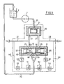
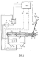
- the device illustrated in FIGS. 1 and 2 comprises a constant flow pump 1 which conveys the hydraulic fluid from a reservoir 2.
- the outlet port of the pump is connected by a conduit 20 to the inlet port 21 of a flow divider 22 having outlet ports 23,24 between which the fluid flow is divided.
- the outlet orifice 23 communicates with the inlet orifice 25 of the electrohydraulic distributor or valve 31 and with a working conduit 27 connected to the chamber 29 of a double-acting cylinder 40.
- the orifice 24 communicates with another inlet orifice 26 of the distributor 31 and with a working conduit 28 connected to the other chamber 30 of the jack 40.
- the jack 40 is part, as is known, of a steering box 41 in which a rack 42 moves mounted at the end of the rod of the jack 40.
- the rack 42 meshes with its control pinion 43 mounted on the end of a steering shaft 44 actuated by a steering wheel 45.
- the steering shaft 44 carries a torque sensor 46 which delivers signals to an electronic processing control 50.
- the electronic control 50 can also receive information on the temperature oil and on the vehicle speed brought by two input channels and coming from temperature sensors and t a c h y-metric sensors or others so as to start the processing of the output signals, of control of the solenoid valves of the distributor 31 when the vehicle is traveling, for example, at less than 5 km / h and when the oil has the optimum viscosity.
- a signal produced in the torque sensor 46 during the rotation of the steering shaft 44 determines at the output of the electronic control 50, a control pulse which arrives via one of the output channels 48,49 to one or the other of the electrically adjustable solenoid valves or flow regulators 51,52 normally closed in the absence of control voltage.
- the adjustable flow regulators 51,52 are inserted in a hydraulic piloting circuit arranged between two fixed flow regulators 53,54 respectively supplied by a pilot conduit 55,56 connected to the working conduit 27,28.
- the adjustable flow regulators 51,52 connected to the connection pipe 70 to the tank 2 are arranged respectively in parallel with two pilot chambers 57,58, limited by the ends and of the drawer 61, / supplied through flow regulators 59 , 60.
- the slide 61 movable in the body 62 of the distributor 31 has in its peri- p h eries two annular grooves 63,64 respectively limited by two shoulders 65,66 axially spaced by a bearing 67.
- the body 62 of dispenser has two working orifices 68, 69 which open respectively into the grooves 63, 64 in contact with the shoulders 65, 66.
- the working orifices 68, 69 are respectively connected by the conduit 70 with the reservoir 2.
- the torque sensor 46 sends information U 1 or U 2 to the electronic control 50 which generates a control signal from the regulator 51 or 52 according to the desired turning direction.
- the signal controls the regulator 51 and that the regulator 52 remains closed.
- the flow rate in the pilot duct 56 is zero.
- the pressure in the pilot chamber 58 is equal to the pressure drop across the orifice 69.
- the opening of the regulator 51 creates a flow in the pilot duct 55.
- the slide 61 is unbalanced and moves to the left of the figure due to a pressure drop in the pilot chamber 57 caused by the opening of the regulator 510
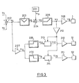
- the voltage U 4 remains zero as long as a minimum torque has not been exceeded.
- the voltage U 4 produced by the comparator 202 is also introduced at the input of a high gain amplifier 207 whose output voltage U 9 is equal to its saturation value. This voltage is applied to the inputs of two networks 208 and 209, the first supplying an output voltage only for the positive values of U 9 , the second only for the negative values.
- the voltage U 7 amplified by the all-or-nothing amplifier 212 is applied to two logic members AND to two inputs denoted respectively 213 and 214, the voltages applied to the second inputs of these members being respectively U 10 and U 11 which are the voltages network output 208.2090
- the member 213 will only supply an output voltage U 12 if the voltage U 9 is positive and the command setpoint for the discharge pressure not zero, and the same for the member 214 It is therefore ultimately these voltages U 12 and U 13 which will supply the power amplifiers 210 and 211 controlling the regulators 51, 52.
- the voltages U 1 and U 2 are therefore brought into opposition without a comparator 202 whose output voltage U 4 is admitted to the input of a network 203 responsible for developing an output voltage U 5 equal to the absolute value of the difference between the voltages U 1 and U 2 : it is therefore the image of the intensity of the torque applied to the steering wheel by the driver.
- This voltage U 5 is compared by a member 204 to the voltage U 3 emitted by at least the speed detector 201 and the resulting voltage U 6 is introduced into a network 205 whose output voltage U 7 remains zero as long as the voltage U 6 is negative and proportional to U 6 otherwise.
- a power amplifier 206 allows the need to develop the voltage U 8 for controlling the discharge pressure of the hydraulic generating unit 1.
Landscapes
- Engineering & Computer Science (AREA)
- Chemical & Material Sciences (AREA)
- Combustion & Propulsion (AREA)
- Transportation (AREA)
- Mechanical Engineering (AREA)
- Steering Control In Accordance With Driving Conditions (AREA)
Applications Claiming Priority (2)
| Application Number | Priority Date | Filing Date | Title |
|---|---|---|---|
| FR8301522 | 1983-02-01 | ||
| FR8301522A FR2540220A1 (fr) | 1983-02-01 | 1983-02-01 | Dispositif de commande hydraulique, notamment de direction assistee |
Publications (3)
| Publication Number | Publication Date |
|---|---|
| EP0115464A2 true EP0115464A2 (de) | 1984-08-08 |
| EP0115464A3 EP0115464A3 (en) | 1984-08-22 |
| EP0115464B1 EP0115464B1 (de) | 1986-11-20 |
Family
ID=9285485
Family Applications (1)
| Application Number | Title | Priority Date | Filing Date |
|---|---|---|---|
| EP84400208A Expired EP0115464B1 (de) | 1983-02-01 | 1984-01-31 | Hydraulische Kontrolleinrichtung, insbesondere für Servolenkung |
Country Status (4)
| Country | Link |
|---|---|
| US (1) | US4549468A (de) |
| EP (1) | EP0115464B1 (de) |
| DE (1) | DE3461360D1 (de) |
| FR (1) | FR2540220A1 (de) |
Families Citing this family (7)
| Publication number | Priority date | Publication date | Assignee | Title |
|---|---|---|---|---|
| US5230396A (en) * | 1988-09-13 | 1993-07-27 | Aisin Seiki Kabushiki Kaisha | Steering control apparatus |
| US5313389A (en) * | 1988-09-13 | 1994-05-17 | Aisin Seiki Kabushiki Kaisha | Fail-safe mechanism for vehicle stability augmentation steering system |
| US5159553A (en) * | 1988-09-13 | 1992-10-27 | Aisin Seiki Kabushiki Kaisha | Steering control apparatus |
| JP3211434B2 (ja) * | 1991-12-18 | 2001-09-25 | アイシン精機株式会社 | 車輛誘導制御装置 |
| US5445239A (en) * | 1994-08-01 | 1995-08-29 | General Motors Corporation | Motor vehicle power steering system |
| DE19617566C2 (de) * | 1996-05-02 | 1998-04-02 | Daimler Benz Ag | Hydraulische Servolenkung eines Kraftfahrzeuges |
| WO2006076138A2 (en) * | 2005-01-11 | 2006-07-20 | Eddy Allan Balma | A method for manufacturing a percussion instrument |
Family Cites Families (6)
| Publication number | Priority date | Publication date | Assignee | Title |
|---|---|---|---|---|
| ES304847A1 (es) * | 1963-12-13 | 1965-03-16 | Fabbrica Italiana Magneti Marelli S P A | Dispositivo para controlar el accionamiento de la servodireccion. |
| US3987702A (en) * | 1970-08-21 | 1976-10-26 | Messerschmitt-Bolkow-Blohm Gmbh | Method and device for electrohydraulic control of a hydraulic actuator |
| FR2188074A1 (de) * | 1972-06-15 | 1974-01-18 | Peugeot & Renault | |
| FR2205875A5 (de) * | 1972-11-06 | 1974-05-31 | Peugeot & Renault | |
| FR2321417A1 (fr) * | 1975-08-21 | 1977-03-18 | Dba | Dispositif hydraulique d'assistance de direction de vehicule automobile |
| DE2946274C2 (de) * | 1979-11-16 | 1981-11-12 | Danfoss A/S, 6430 Nordborg | Hydraulische Steuervorrichtung, insbesondere Lenkvorrichtung |
-
1983
- 1983-02-01 FR FR8301522A patent/FR2540220A1/fr active Granted
-
1984
- 1984-01-31 EP EP84400208A patent/EP0115464B1/de not_active Expired
- 1984-01-31 DE DE8484400208T patent/DE3461360D1/de not_active Expired
- 1984-02-01 US US06/575,987 patent/US4549468A/en not_active Expired - Fee Related
Also Published As
| Publication number | Publication date |
|---|---|
| FR2540220A1 (fr) | 1984-08-03 |
| DE3461360D1 (en) | 1987-01-08 |
| EP0115464B1 (de) | 1986-11-20 |
| US4549468A (en) | 1985-10-29 |
| EP0115464A3 (en) | 1984-08-22 |
| FR2540220B1 (de) | 1985-05-10 |
Similar Documents
| Publication | Publication Date | Title |
|---|---|---|
| US4574905A (en) | Steering force controlling apparatus for power steering system | |
| US6041883A (en) | Flow controlling apparatus for power steering systems | |
| FR2493949A1 (fr) | Dispositif de reglage et de commande pour le reglage du moment de rotation de sortie dans un mecanisme hydrostatique avec commande en cascade de la puissance limite | |
| US6427441B2 (en) | Hydrostatic vehicle drive with control device and control device for hydrostatic drives | |
| EP0115464B1 (de) | Hydraulische Kontrolleinrichtung, insbesondere für Servolenkung | |
| JPS61247575A (ja) | 動力舵取装置の操舵力制御装置 | |
| EP0194927B1 (de) | Drucksteuer-Servoeinrichtung für hydraulische Anlage, insbesondere für Kraftfahrzeugservolenkung | |
| FR2578590A1 (fr) | Dispositif a soupapes de commande, comportant deux blocs de commande, pour plusieurs mecanismes hydrauliques, en particulier ceux d'appareils mobiles | |
| JPH0577744A (ja) | パワーステアリング装置 | |
| FR2508116A2 (fr) | Dispositif pour regler un organe variable en fonction d'une grandeur de reglage et d'une grandeur de commande, en particulier, pour regler le mecanisme de levage d'une remorque, d'une batteuse, etc. | |
| JPS60229870A (ja) | 動力舵取装置の操舵力制御装置 | |
| CN101022986B (zh) | 转向助力系统 | |
| FR2563172A1 (fr) | Dispositif de direction de vehicules, commutable selectivement entre un mode de direction manuelle et un mode de guidage transversal automatique | |
| JPS60248479A (ja) | 動力舵取装置の操舵力制御装置 | |
| US4689955A (en) | Vibration roller having a power limiting device | |
| US4947951A (en) | Pressure responsive and electrically controllable flow control apparatus | |
| FR2511463A1 (fr) | Commande du couple d'entree pour une transmission hydraulique a cylindree variable | |
| CA2231340A1 (fr) | Procede d'asservissement d'une servovalve pouvant etre asservie en debit et en pression | |
| FR2647876A1 (fr) | Modulateur et circuit de direction assistee comprenant un tel modulateur | |
| EP0262007B1 (de) | Durchflusskontrolle-Nachlaufeinrichtung für hydraulische Anlage, insbesondere für Kraftfahrzeug-Servolenkung | |
| JPS58209655A (ja) | 動力舵取装置の操舵力制御装置 | |
| JPS62139755A (ja) | 動力舵取装置の操舵力制御装置 | |
| JPS582100B2 (ja) | 動力舵取装置の操舵力制御装置 | |
| JPH024863Y2 (de) | ||
| JPS6299262A (ja) | 動力舵取装置の操舵力制御装置 |
Legal Events
| Date | Code | Title | Description |
|---|---|---|---|
| PUAI | Public reference made under article 153(3) epc to a published international application that has entered the european phase |
Free format text: ORIGINAL CODE: 0009012 |
|
| PUAL | Search report despatched |
Free format text: ORIGINAL CODE: 0009013 |
|
| 17P | Request for examination filed |
Effective date: 19840203 |
|
| AK | Designated contracting states |
Designated state(s): BE DE GB IT NL |
|
| AK | Designated contracting states |
Designated state(s): BE DE GB IT NL |
|
| GRAA | (expected) grant |
Free format text: ORIGINAL CODE: 0009210 |
|
| AK | Designated contracting states |
Kind code of ref document: B1 Designated state(s): BE DE GB IT NL |
|
| ITF | It: translation for a ep patent filed | ||
| REF | Corresponds to: |
Ref document number: 3461360 Country of ref document: DE Date of ref document: 19870108 |
|
| PGFP | Annual fee paid to national office [announced via postgrant information from national office to epo] |
Ref country code: NL Payment date: 19870131 Year of fee payment: 4 |
|
| PLBE | No opposition filed within time limit |
Free format text: ORIGINAL CODE: 0009261 |
|
| STAA | Information on the status of an ep patent application or granted ep patent |
Free format text: STATUS: NO OPPOSITION FILED WITHIN TIME LIMIT |
|
| 26N | No opposition filed | ||
| PG25 | Lapsed in a contracting state [announced via postgrant information from national office to epo] |
Ref country code: GB Effective date: 19890131 Ref country code: BE Effective date: 19890131 |
|
| BERE | Be: lapsed |
Owner name: REGIE NATIONALE DES USINES RENAULT Effective date: 19890131 |
|
| PG25 | Lapsed in a contracting state [announced via postgrant information from national office to epo] |
Ref country code: NL Effective date: 19890801 |
|
| NLV4 | Nl: lapsed or anulled due to non-payment of the annual fee | ||
| GBPC | Gb: european patent ceased through non-payment of renewal fee | ||
| PG25 | Lapsed in a contracting state [announced via postgrant information from national office to epo] |
Ref country code: DE Effective date: 19891003 |