EP0114580B1 - Statisch bestimmter rollender Träger mit drehbaren Körpern verwendet als sich drehender Ring beim Ringspinnen - Google Patents
Statisch bestimmter rollender Träger mit drehbaren Körpern verwendet als sich drehender Ring beim Ringspinnen Download PDFInfo
- Publication number
- EP0114580B1 EP0114580B1 EP83830238A EP83830238A EP0114580B1 EP 0114580 B1 EP0114580 B1 EP 0114580B1 EP 83830238 A EP83830238 A EP 83830238A EP 83830238 A EP83830238 A EP 83830238A EP 0114580 B1 EP0114580 B1 EP 0114580B1
- Authority
- EP
- European Patent Office
- Prior art keywords
- ring
- cage
- hereinbefore
- revolvable
- bodies
- Prior art date
- Legal status (The legal status is an assumption and is not a legal conclusion. Google has not performed a legal analysis and makes no representation as to the accuracy of the status listed.)
- Expired
Links
- 238000005096 rolling process Methods 0.000 title claims abstract description 18
- 238000007378 ring spinning Methods 0.000 title description 4
- 230000036316 preload Effects 0.000 claims abstract description 4
- 230000009471 action Effects 0.000 claims description 20
- 238000009987 spinning Methods 0.000 claims description 12
- 239000000314 lubricant Substances 0.000 claims description 7
- 238000005461 lubrication Methods 0.000 claims description 6
- 238000006073 displacement reaction Methods 0.000 claims description 5
- 230000008878 coupling Effects 0.000 claims description 3
- 238000010168 coupling process Methods 0.000 claims description 3
- 238000005859 coupling reaction Methods 0.000 claims description 3
- 238000013016 damping Methods 0.000 claims description 3
- 230000033001 locomotion Effects 0.000 description 10
- 239000003921 oil Substances 0.000 description 9
- 238000006243 chemical reaction Methods 0.000 description 5
- 230000003068 static effect Effects 0.000 description 4
- 230000001052 transient effect Effects 0.000 description 4
- 239000000463 material Substances 0.000 description 3
- 238000004804 winding Methods 0.000 description 3
- 230000008901 benefit Effects 0.000 description 2
- 230000008859 change Effects 0.000 description 2
- 238000009434 installation Methods 0.000 description 2
- 229910052751 metal Inorganic materials 0.000 description 2
- 238000000034 method Methods 0.000 description 2
- 230000008569 process Effects 0.000 description 2
- 229920001187 thermosetting polymer Polymers 0.000 description 2
- 238000012546 transfer Methods 0.000 description 2
- 229910000831 Steel Inorganic materials 0.000 description 1
- 230000033228 biological regulation Effects 0.000 description 1
- 238000010276 construction Methods 0.000 description 1
- 230000007423 decrease Effects 0.000 description 1
- 238000013461 design Methods 0.000 description 1
- 238000009826 distribution Methods 0.000 description 1
- 230000000694 effects Effects 0.000 description 1
- 230000001771 impaired effect Effects 0.000 description 1
- 230000007774 longterm Effects 0.000 description 1
- 239000010687 lubricating oil Substances 0.000 description 1
- 230000005415 magnetization Effects 0.000 description 1
- 239000002184 metal Substances 0.000 description 1
- 239000007769 metal material Substances 0.000 description 1
- 238000013021 overheating Methods 0.000 description 1
- 238000012545 processing Methods 0.000 description 1
- 239000011347 resin Substances 0.000 description 1
- 229920005989 resin Polymers 0.000 description 1
- 239000010959 steel Substances 0.000 description 1
- 230000008961 swelling Effects 0.000 description 1
- 230000001360 synchronised effect Effects 0.000 description 1
- 239000002023 wood Substances 0.000 description 1
- 210000002268 wool Anatomy 0.000 description 1
Images


Classifications
-
- F—MECHANICAL ENGINEERING; LIGHTING; HEATING; WEAPONS; BLASTING
- F16—ENGINEERING ELEMENTS AND UNITS; GENERAL MEASURES FOR PRODUCING AND MAINTAINING EFFECTIVE FUNCTIONING OF MACHINES OR INSTALLATIONS; THERMAL INSULATION IN GENERAL
- F16C—SHAFTS; FLEXIBLE SHAFTS; ELEMENTS OR CRANKSHAFT MECHANISMS; ROTARY BODIES OTHER THAN GEARING ELEMENTS; BEARINGS
- F16C27/00—Elastic or yielding bearings or bearing supports, for exclusively rotary movement
- F16C27/04—Ball or roller bearings, e.g. with resilient rolling bodies
-
- D—TEXTILES; PAPER
- D01—NATURAL OR MAN-MADE THREADS OR FIBRES; SPINNING
- D01H—SPINNING OR TWISTING
- D01H7/00—Spinning or twisting arrangements
- D01H7/02—Spinning or twisting arrangements for imparting permanent twist
- D01H7/52—Ring-and-traveller arrangements
- D01H7/56—Ring-and-traveller arrangements with freely-rotatable rings; with braked or dragged rings ; Lubricating arrangements therefor
-
- F—MECHANICAL ENGINEERING; LIGHTING; HEATING; WEAPONS; BLASTING
- F16—ENGINEERING ELEMENTS AND UNITS; GENERAL MEASURES FOR PRODUCING AND MAINTAINING EFFECTIVE FUNCTIONING OF MACHINES OR INSTALLATIONS; THERMAL INSULATION IN GENERAL
- F16C—SHAFTS; FLEXIBLE SHAFTS; ELEMENTS OR CRANKSHAFT MECHANISMS; ROTARY BODIES OTHER THAN GEARING ELEMENTS; BEARINGS
- F16C19/00—Bearings with rolling contact, for exclusively rotary movement
- F16C19/02—Bearings with rolling contact, for exclusively rotary movement with bearing balls essentially of the same size in one or more circular rows
- F16C19/04—Bearings with rolling contact, for exclusively rotary movement with bearing balls essentially of the same size in one or more circular rows for radial load mainly
- F16C19/06—Bearings with rolling contact, for exclusively rotary movement with bearing balls essentially of the same size in one or more circular rows for radial load mainly with a single row or balls
-
- F—MECHANICAL ENGINEERING; LIGHTING; HEATING; WEAPONS; BLASTING
- F16—ENGINEERING ELEMENTS AND UNITS; GENERAL MEASURES FOR PRODUCING AND MAINTAINING EFFECTIVE FUNCTIONING OF MACHINES OR INSTALLATIONS; THERMAL INSULATION IN GENERAL
- F16C—SHAFTS; FLEXIBLE SHAFTS; ELEMENTS OR CRANKSHAFT MECHANISMS; ROTARY BODIES OTHER THAN GEARING ELEMENTS; BEARINGS
- F16C19/00—Bearings with rolling contact, for exclusively rotary movement
- F16C19/22—Bearings with rolling contact, for exclusively rotary movement with bearing rollers essentially of the same size in one or more circular rows, e.g. needle bearings
- F16C19/24—Bearings with rolling contact, for exclusively rotary movement with bearing rollers essentially of the same size in one or more circular rows, e.g. needle bearings for radial load mainly
- F16C19/26—Bearings with rolling contact, for exclusively rotary movement with bearing rollers essentially of the same size in one or more circular rows, e.g. needle bearings for radial load mainly with a single row of rollers
-
- F—MECHANICAL ENGINEERING; LIGHTING; HEATING; WEAPONS; BLASTING
- F16—ENGINEERING ELEMENTS AND UNITS; GENERAL MEASURES FOR PRODUCING AND MAINTAINING EFFECTIVE FUNCTIONING OF MACHINES OR INSTALLATIONS; THERMAL INSULATION IN GENERAL
- F16C—SHAFTS; FLEXIBLE SHAFTS; ELEMENTS OR CRANKSHAFT MECHANISMS; ROTARY BODIES OTHER THAN GEARING ELEMENTS; BEARINGS
- F16C2340/00—Apparatus for treating textiles
- F16C2340/18—Apparatus for spinning or twisting
Definitions
- This invention concerns devices to provide rolling and support which are employed as rotatable rings in spinning operations.
- the invention concerns a rotatable ring which comprises as a support a device which is similarto a bearing with revolvable bodies, the bearing being of an isostatic type, in that it consists of only the number of components enough and necessary to ensure functioning and the precise determination of constrained reactions in terms of magnitude and point of application (statically determined system).
- Rotatable rings are known in the art which have a supporting device consisting of a ball-bearing and which consist of a pair of concentric rings between which a given number of balls is interposed.
- the invention in question can be likened to a bearing with onlythree revolvable bodies, which is therefore equivalent to the one single isostatic structure that can be embodied with a device to provide rolling.
- the constrained reactions are not only determined but are exactly the same with any load and in any working condition.
- the bearings are sometimes preloaded when they are being fitted.
- Transient phenomena may have a scanty or no importance when there is only one device, but become very important when there is a plurality of devices subject to a centralized control and when such devices have to work at the same speed and in a fully synchronous manner.
- This invention is put forward to obviate the foregoing drawbacks and envisages a new isostatic device to provide rolling and support with revolvable bodies and to be applied as a spinning ring without such an application being deemed to be restrictive.
- a traveller of a suitable weight is used for each kind of yarn so as to determine on the yarn itself the exact tension on the yarn being formed.
- Rotatable rings have also been disclosed (EP-A-0026161) which are fitted to bearings and provide a fixed brake which cooperates by sliding on the rotatable part of the bearing or on the cage that holds the balls; but when such bearings are fitted as components of rotatable spinning rings, they have given unsatisfactory results.
- a magnetic brake (EP-A-0026161) or an eddy- current brake (DE-A-2538420) has also been disclosed which exerts its action on the rotatable part, perhaps with the help of mechanical action.
- the invention envisages an isostatic device to provide rolling and support which is equipped with only three revolvable bodies arranged with one hundred and twenty degrees between them and kept in this geometric position by a one-piece cage made of a non-metallic material.
- Such a device might be wrongly called a bearing owing to the seeming likeness which it bears to such objects.
- a sleeve bearing a small ring is fitted to the inner ring of the device, a resilient brake means being interposed and also acting to absorb vibrations, the functioning being unlike the teaching of US 4,357,791, which discloses static elements having the functions only of damping vibrations and of reducing noise.
- the inner and outer rings which form such a bearing are made of steel and, if the revolvable bodies are balls, are shaped in such a way that they both comprise a groove having the profile of a circular sector with a radius of curvature slightly greater than the radius of the balls employed.
- This device is therefore suitable for withstanding axial and radial loads and can be employed with a horizontal or vertical axis.
- this type of device So as to enable desired and accurate rolling to be obtained in every condition of motion, whether accelerating or slowing down or steady running, this type of device is provided with a heavy preloading without its working life being impaired or altered thereby.
- one of the rings is very stiff and can be deemed not capable of deformation in practice in the example under consideration, whereas the other ring, although having a section with a high moment of inertia which enables it to withstand the loads required, can be readily deformed owing to its circumferential slenderness.
- the stiff ring can have any section provided that its race has the right section and a suitable surface.
- the other ring which we shall call elastic herein, has to comprise a suitably cut race but also has to have a suitable section which permits a suitable degree of deformation of the circumference through geometric contact.
- the section of this elastic ring can be C-shaped or can have other shapes suitable for the purpose.
- the C-shaped section has to ensure enough crosswise stiffness to prevent warping and any crosswise deformation. At the same time it has to permit elastic circumferential deformations due to its contact with the revolvable bodies, which are always kept under load in this way.
- the elastic ring will be the inner one advantageously if it is employed as a rotatable ring.
- the circumference of contact (between the race and the revolvable bodies) of the inner elastic ring will be greater than the nominal geometric dimension so that a certain desired degree of interference takes place.
- the ring will therefore become deformed and will deviate from its pure circumference so as to take up a substantiallythree-lobed configuration.
- This deformation of the ring will generate on it stresses which will be transmitted to the revolvable bodies either as an increase of the elastic impression between the revolvable body and outer ring and between the revolvable body and inner ring (an increase of the ellipses of contact) or as a permanent load.
- the friction between the revolvable bodies-and the rings will be proportional to the value of the load, with the consequent advantage that transient motions will always take place during rolling without slipping movements.
- Such a condition also entails a certain resisting moment, which may be necessary in given cases, just as in fact it is in an application such as a spinning ring.
- the cage which keeps the balls positioned geometrically as required at angles of one hundred and twenty degrees consists substantially of a ring with a suitable section, rectangular for instance, and with sizes such as will contain a hole having a diameter greater than the diameter of the ball and having outer and inner diameters such as can be contained in the free space remaining between the races of the bearing.
- the diameters of the cage are such as to obtain asymmetry, that is to say, the mean circumference of the cage does not coincide with the circumference on which the balls lie but is offset towards the movable ring.
- the purpose of this is that the inevitable eccentric positioning of the cage during running will be of the minimum possible value (small gap between the cage and the inner ring).
- a suitable material for construction of the cage is a thermosetting resin reinforced with fibres or wood and perhaps having a certain porosity, which is a property that can be exploited to impregnate the cage with lubricant and thus to provide the device with an efficient lubrication system.
- Lubrication of the device has been purposely studied so as to achieve minimal lubrication.
- One embodiment envisages that a wool thread acting as a wick to deliver lubricant is stretched between two holes made in the static ring for this purpose. This wick reaches into an oil bath and becomes impregnated by capillary action.
- Another embodiment which can be employed more advantageously with revolvable bodies consisting of rollers, envisages that the feeder wick cooperates with a zone of the race, or a zone very close to the rolling race, which does not cooperate with the revolvable body.
- the invention provides regulation of the tensioning load with an auxiliary device which comprises a certain number of permanent magnets or electromagnets. These magnets can be disposed with concordant polarities or alternate polarities (and are then always in an even number).
- the magnets are - arranged advantageously with alternate polarities and thus bring about a continuous magnetic field that ensures efficient and even braking action, which would otherwise not be possible with a layout of concordant polarities, in which the magnetic field created has zones where its action is nil.
- the movable ring in the state of rest is magnetized in sectors according to the polarities induced by the pairs of poles situated before each sector.
- the movable ring When the movable ring takes up its normal rotary motion, it transfers during that motion each already magnetized sector from a concordant field to a discordant field, and thus a resistant force arises which is as much greater as the magnetic field generated is greater.
- Immovable pole pieces can be located between the ring and the magnets, or electromagnets, to vary the resistant force and the magnets are fitted to a movable holder on a plane parallel to the plane of the movable ring.
- the invention envisages as a variant an interference with the magnetic field on the cage as well.
- Such an interference can be obtained by coupling to the cage one or more suitably arranged metallic elements.
- the invention is therefore embodied with a statically determined device to provide rolling and support with revolvable bodies, employed as a rotatable ring in spinning operations, which comprises an inner ring, an outer ring, a cage and three revolvable bodies fitted substantially at angles of one hundred and twenty degrees from each other, in which device the revolvable bodies are kept in position by the cage, characterised in that the mean circumference of the cage is offset inwards in relation to the median circumference of rolling of the revolvable bodies, and one ring is substantially stiff and the other ring is resilient with a suitable degree of contact with the revolvable bodies so that, after being fitted, the resilient ring tends to take up a three-lobed conformation, thus providing a pre-set pre-load for the revolvable bodies.
- the invention is also embodied with a device comprising adjustable braking means and capable of being used as a rotatable ring.
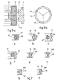
- an outer ring 11 of a device 10 is embodied as being stiff, whereas an inner ring 12 is embodied as being resilient.
- This embodiment is specifically intended for application of the device to rotatable spinning rings.
- the inner ring 12 has a C-shaped section but could have any other section suitable for the purpose as in Figs. 7 or still others.
- the configuration of the outer ring 11 will be such as to give the necessary stiffness and the required capability of installation.
- the device 10 comprises three revolvable bodies 14 situated at angles of one hundred and twenty degrees along the circumference, and the inner diameter of their trajectory is slightly smaller than the diameter of the innermost part of a groove on a face 16 of the inner ring 12. The result is that there is contact during installation; this contact will be according to the design made and will therefore produce a suitable radial load on the revolvable bodies 14.
- This contact causes the ring 12, after being installed, to take up a three-lobed shape continuously.
- a face 15 of the cage 13 is, therefore, near a face 16, although the two faces may touch each other at random during working.
- the outer ring 11 comprises two or more holes 17 through which a wick 18 passes; the wick 18 is stretched between the holes 17 and picks up oil from an oil bath 19 and brushes against a face 20 of the cage 13 suitably.
- the wick 18 in Fig. 1b can preferably, but not essentially, also cooperate with discharge grooves 136 if rollers 114 are comprised (but this embodiment can also be applied to balls 14).
- the wick 18 feeds lubricating oil by capillary action to the face 20 of the cage 13, whence the oil reaches the revolvable bodies 14, or the wick 18 feeds oil directly to the revolvable bodies 14 themselves, which are thus always lubricated, a metal-to-metal contact being prevented in this way.
- the lubrication will advantageously be of a type called minimal.
- the cage 13 has the advantage that it can be made in one single piece of great dimensional accuracy and advantageously of a thermosetting material possibly reinforced with another material suitable for the purpose.
- the device 10 When the device 10 is employed as a rotatable ring 21 for spinning operations, it will be fitted to a suitable support 22 which comprises appropriate seatings.
- the support 22 will also provide suitable shields 23-123.
- An appropriate sleeve 24 is fitted in cooperation with the inner ring 12 and comprises a suitable anchorage seating for a small ring 25.
- the sleeve 24 can have an appropriate swelling 124 for better anchorage to the inner ring 12. This anchorage is obtained advantageously with a damping and coupling ring 37 interposed.
- the invention provides a plurality of permanent magnets or electromagnets 26 fitted alongside one another with their polarities advantageously, but not necessarily, reversed in relation to each other, in which case the magnets 26 will be in an even number.
- metallic pole pieces 27 are envisaged which are able to transfer the magnetic action from the magnets 26 to the inner ring 12.
- the displacement of the magnets 26 can be carried out by angular rotation (Fig. 4), or by radial displacement (not shown), or by angular displacement on an inclined arm (Fig. 5) through cooperation of movable pins 33 with substantially stationary slots 34, the magnets 26 being rotated on a pivot or axis of pivoting 32.
- Each of these systems can be actuated by one single centralized device 28 that controls all the rotatable rings 21 fitted to a ring rail 29.
- a shaft 28 is moved axially and acts on a lever 30 which rotates a support 31 that bears the magnets 26.
- the lever 30 can be detached from the shaft 28 by a lowering action 35 so as to be able to act on each rotatable ring 21 individually.
- the magnet 26 pivots at 32 and the pin 33 cooperates with an appropriate slot 34 comprised in the support 31, so that the magnet 26 is made to rotate around the pivot 32.
- the action of the magnets 26 or of the pole pieces 27 can also act on the cage 13 (Fig. 6a) if the cage 13 comprises one or more metallic means 113 sensitive to magnets.
- Fig. 6b shows three clips 113 cooperating with the cage 13 near the revolvable bodies 14.
Landscapes
- Engineering & Computer Science (AREA)
- Mechanical Engineering (AREA)
- General Engineering & Computer Science (AREA)
- Textile Engineering (AREA)
- Rolling Contact Bearings (AREA)
- Invalid Beds And Related Equipment (AREA)
- Toys (AREA)
- Support Of The Bearing (AREA)
- Spinning Or Twisting Of Yarns (AREA)
Claims (15)
Priority Applications (1)
| Application Number | Priority Date | Filing Date | Title |
|---|---|---|---|
| AT83830238T ATE24940T1 (de) | 1982-12-23 | 1983-11-28 | Statisch bestimmter rollender traeger mit drehbaren koerpern verwendet als sich drehender ring beim ringspinnen. |
Applications Claiming Priority (2)
| Application Number | Priority Date | Filing Date | Title |
|---|---|---|---|
| IT8283506A IT1210038B (it) | 1982-12-23 | 1982-12-23 | Dispositivo di sostentamento e rotolamento isostatico a corpi volventi quale anello rotante. |
| IT8350682 | 1982-12-23 |
Publications (3)
| Publication Number | Publication Date |
|---|---|
| EP0114580A2 EP0114580A2 (de) | 1984-08-01 |
| EP0114580A3 EP0114580A3 (en) | 1984-08-15 |
| EP0114580B1 true EP0114580B1 (de) | 1987-01-14 |
Family
ID=11322687
Family Applications (1)
| Application Number | Title | Priority Date | Filing Date |
|---|---|---|---|
| EP83830238A Expired EP0114580B1 (de) | 1982-12-23 | 1983-11-28 | Statisch bestimmter rollender Träger mit drehbaren Körpern verwendet als sich drehender Ring beim Ringspinnen |
Country Status (6)
| Country | Link |
|---|---|
| US (1) | US4548518A (de) |
| EP (1) | EP0114580B1 (de) |
| JP (1) | JPS59168137A (de) |
| AT (1) | ATE24940T1 (de) |
| DE (1) | DE3369165D1 (de) |
| IT (1) | IT1210038B (de) |
Families Citing this family (11)
| Publication number | Priority date | Publication date | Assignee | Title |
|---|---|---|---|---|
| DE4033592A1 (de) * | 1990-10-23 | 1992-05-07 | Gkn Automotive Ag | Elastisches mittellager fuer eine laengswelle |
| JP2541679Y2 (ja) * | 1991-07-02 | 1997-07-16 | 株式会社シマノ | 釣り用リールの軸支構造 |
| AU3485395A (en) * | 1994-09-16 | 1996-03-29 | Nippo Ltd. | Spinning ring |
| US6113277A (en) * | 1997-07-31 | 2000-09-05 | Seagate Technology Llc | Actuator pivot bearing with reduced hysteresis |
| GB201201498D0 (en) * | 2012-01-30 | 2012-03-14 | Rolls Royce Plc | Bearing assembly |
| ITUB20151069A1 (it) * | 2015-05-26 | 2016-11-26 | Cogne Macch Tessili S P A | Dispositivo di torsione e avvolgimento di un filo su un fuso |
| JP6634785B2 (ja) * | 2015-11-16 | 2020-01-22 | 株式会社ジェイテクト | 転がり軸受 |
| JP2017089844A (ja) * | 2015-11-16 | 2017-05-25 | 株式会社ジェイテクト | 転がり軸受 |
| JP6613845B2 (ja) * | 2015-11-25 | 2019-12-04 | 株式会社ジェイテクト | 転がり軸受 |
| JP6728901B2 (ja) * | 2016-04-04 | 2020-07-22 | 株式会社ジェイテクト | 転がり軸受 |
| JP2018066453A (ja) * | 2016-10-21 | 2018-04-26 | 株式会社ジェイテクト | 転がり軸受 |
Family Cites Families (11)
| Publication number | Priority date | Publication date | Assignee | Title |
|---|---|---|---|---|
| US1160594A (en) * | 1915-02-13 | 1915-11-16 | Walter E Graham | Roller-bearing. |
| US2034762A (en) * | 1934-01-05 | 1936-03-24 | Kuwada Gompei | Spinning ring |
| US2563187A (en) * | 1951-03-02 | 1951-08-07 | Ernest Pennati | Variable-speed rotating ring for spinning machines |
| GB877491A (en) * | 1957-09-11 | 1961-09-13 | Merriman Bros Inc | Improvements relating to spinning rings and holders therefor |
| US2932152A (en) * | 1958-05-28 | 1960-04-12 | Chemstrand Corp | Textile twisting apparatus |
| US3628836A (en) * | 1969-12-17 | 1971-12-21 | United Aircraft Corp | Roller bearing |
| FR2271443B2 (de) * | 1974-01-23 | 1977-06-10 | Pitner Alfred | |
| DE2538420C2 (de) * | 1975-08-29 | 1985-04-04 | Zinser Textilmaschinen Gmbh, 7333 Ebersbach | Ringspinn- oder Ringzwirnmaschine |
| SU572597A1 (ru) * | 1975-12-02 | 1977-09-15 | Предприятие П/Я А-1665 | Упруга опора качени |
| IT7983458A0 (it) * | 1979-09-24 | 1979-09-24 | Pordenone | Anello rotante. |
| US4357791A (en) * | 1981-03-12 | 1982-11-09 | Hope Plastics Corporation | Noise and vibration dampening ring mount |
-
1982
- 1982-12-23 IT IT8283506A patent/IT1210038B/it active
-
1983
- 1983-11-28 AT AT83830238T patent/ATE24940T1/de not_active IP Right Cessation
- 1983-11-28 DE DE8383830238T patent/DE3369165D1/de not_active Expired
- 1983-11-28 EP EP83830238A patent/EP0114580B1/de not_active Expired
- 1983-12-20 US US06/563,565 patent/US4548518A/en not_active Expired - Fee Related
- 1983-12-22 JP JP58243018A patent/JPS59168137A/ja active Pending
Also Published As
| Publication number | Publication date |
|---|---|
| ATE24940T1 (de) | 1987-01-15 |
| JPS59168137A (ja) | 1984-09-21 |
| EP0114580A2 (de) | 1984-08-01 |
| DE3369165D1 (en) | 1987-02-19 |
| US4548518A (en) | 1985-10-22 |
| EP0114580A3 (en) | 1984-08-15 |
| IT8283506A0 (it) | 1982-12-23 |
| IT1210038B (it) | 1989-09-06 |
Similar Documents
| Publication | Publication Date | Title |
|---|---|---|
| EP0114580B1 (de) | Statisch bestimmter rollender Träger mit drehbaren Körpern verwendet als sich drehender Ring beim Ringspinnen | |
| US4128280A (en) | Self-pressurizing floating gas bearing having a magnetic bearing therein | |
| US8063525B2 (en) | Retainer bearing for an electric machine, and electric machine comprising at least one such retainer bearing | |
| GB1595371A (en) | Rotors which are to be rotated at supercritical speeds | |
| KR940010188B1 (ko) | 스핀들 축용 베어링 구조 | |
| JPH0686688B2 (ja) | 紡績用回転リングの軸承装置 | |
| EP0830514A1 (de) | Kippsegmentlager | |
| US2350272A (en) | Spindle | |
| CA2940967C (en) | Rotary machine having magnetic and mechanical bearings | |
| US3020106A (en) | Bearings having balls with restrained spin axes | |
| CN110762119A (zh) | 一种滚动轴承 | |
| US3645590A (en) | Carbon-graphite gas-bearing roll | |
| US3910657A (en) | Rolling members prestressed by a radially resilient ring | |
| JPS599312A (ja) | 磁性流体磁気軸受 | |
| US4346949A (en) | Rotor assembly provided with a bearing having virtually zero axial clearance | |
| US3899221A (en) | Thrust bearings | |
| DK1440499T3 (en) | Method of placing an electric machine on bearings and bearing assembly in an electric machine | |
| US2794692A (en) | High speed bearing | |
| JPS6028928B2 (ja) | リング精紡機或いはリング撚糸機 | |
| JPH1182522A (ja) | 磁気軸受装置のタッチダウン軸受 | |
| US3491529A (en) | Textile spinning spindle assembly | |
| CN223609116U (zh) | 一种角接触球轴承保持架和角接触球轴承 | |
| US2581173A (en) | Bearing assembly | |
| US3369850A (en) | Quill type roller bearing | |
| CN202326717U (zh) | 一种内、外组件均为圆柱滚子的三环轴承 |
Legal Events
| Date | Code | Title | Description |
|---|---|---|---|
| PUAI | Public reference made under article 153(3) epc to a published international application that has entered the european phase |
Free format text: ORIGINAL CODE: 0009012 |
|
| PUAL | Search report despatched |
Free format text: ORIGINAL CODE: 0009013 |
|
| AK | Designated contracting states |
Designated state(s): AT BE CH DE FR GB LI NL |
|
| AK | Designated contracting states |
Designated state(s): AT BE CH DE FR GB LI NL |
|
| 17P | Request for examination filed |
Effective date: 19840911 |
|
| RAP1 | Party data changed (applicant data changed or rights of an application transferred) |
Owner name: FAG CUSCINETTI SPA Owner name: OFFICINE SAVIO S.P.A. |
|
| GRAA | (expected) grant |
Free format text: ORIGINAL CODE: 0009210 |
|
| AK | Designated contracting states |
Kind code of ref document: B1 Designated state(s): AT BE CH DE FR GB LI NL |
|
| REF | Corresponds to: |
Ref document number: 24940 Country of ref document: AT Date of ref document: 19870115 Kind code of ref document: T |
|
| REF | Corresponds to: |
Ref document number: 3369165 Country of ref document: DE Date of ref document: 19870219 |
|
| ET | Fr: translation filed | ||
| PLBE | No opposition filed within time limit |
Free format text: ORIGINAL CODE: 0009261 |
|
| STAA | Information on the status of an ep patent application or granted ep patent |
Free format text: STATUS: NO OPPOSITION FILED WITHIN TIME LIMIT |
|
| 26N | No opposition filed | ||
| REG | Reference to a national code |
Ref country code: CH Ref legal event code: PUE Owner name: SAVIO S.P.A. |
|
| NLV4 | Nl: lapsed or anulled due to non-payment of the annual fee | ||
| REG | Reference to a national code |
Ref country code: FR Ref legal event code: CD |
|
| NLS | Nl: assignments of ep-patents |
Owner name: SAVIO S.P.A. TE PORDENONE EN FAG CUSCINETTI SPA TE |
|
| REG | Reference to a national code |
Ref country code: GB Ref legal event code: 732 |
|
| PGFP | Annual fee paid to national office [announced via postgrant information from national office to epo] |
Ref country code: BE Payment date: 19951116 Year of fee payment: 13 |
|
| PGFP | Annual fee paid to national office [announced via postgrant information from national office to epo] |
Ref country code: GB Payment date: 19951124 Year of fee payment: 13 |
|
| PGFP | Annual fee paid to national office [announced via postgrant information from national office to epo] |
Ref country code: NL Payment date: 19951130 Year of fee payment: 13 Ref country code: DE Payment date: 19951130 Year of fee payment: 13 Ref country code: AT Payment date: 19951130 Year of fee payment: 13 |
|
| PGFP | Annual fee paid to national office [announced via postgrant information from national office to epo] |
Ref country code: CH Payment date: 19951201 Year of fee payment: 13 |
|
| PG25 | Lapsed in a contracting state [announced via postgrant information from national office to epo] |
Ref country code: GB Effective date: 19961128 Ref country code: AT Effective date: 19961128 |
|
| PG25 | Lapsed in a contracting state [announced via postgrant information from national office to epo] |
Ref country code: LI Effective date: 19961130 Ref country code: CH Effective date: 19961130 Ref country code: BE Effective date: 19961130 |
|
| BERE | Be: lapsed |
Owner name: FAG CUSCINETTI S.P.A. Effective date: 19961130 Owner name: SAVIO S.P.A. Effective date: 19961130 |
|
| PG25 | Lapsed in a contracting state [announced via postgrant information from national office to epo] |
Ref country code: NL Effective date: 19970601 |
|
| REG | Reference to a national code |
Ref country code: CH Ref legal event code: PL |
|
| GBPC | Gb: european patent ceased through non-payment of renewal fee |
Effective date: 19961128 |
|
| NLV4 | Nl: lapsed or anulled due to non-payment of the annual fee |
Effective date: 19970601 |
|
| PG25 | Lapsed in a contracting state [announced via postgrant information from national office to epo] |
Ref country code: DE Effective date: 19970801 |
|
| PGFP | Annual fee paid to national office [announced via postgrant information from national office to epo] |
Ref country code: FR Payment date: 19981110 Year of fee payment: 16 |
|
| PG25 | Lapsed in a contracting state [announced via postgrant information from national office to epo] |
Ref country code: FR Free format text: LAPSE BECAUSE OF NON-PAYMENT OF DUE FEES Effective date: 20000731 |
|
| REG | Reference to a national code |
Ref country code: FR Ref legal event code: ST |