EP0113155A1 - Device for moving a pile of objects such as boxes or bags - Google Patents
Device for moving a pile of objects such as boxes or bags Download PDFInfo
- Publication number
- EP0113155A1 EP0113155A1 EP83201867A EP83201867A EP0113155A1 EP 0113155 A1 EP0113155 A1 EP 0113155A1 EP 83201867 A EP83201867 A EP 83201867A EP 83201867 A EP83201867 A EP 83201867A EP 0113155 A1 EP0113155 A1 EP 0113155A1
- Authority
- EP
- European Patent Office
- Prior art keywords
- frame
- supporting
- carrying frame
- stack
- pushing
- Prior art date
- Legal status (The legal status is an assumption and is not a legal conclusion. Google has not performed a legal analysis and makes no representation as to the accuracy of the status listed.)
- Granted
Links
Images


Classifications
-
- B—PERFORMING OPERATIONS; TRANSPORTING
- B66—HOISTING; LIFTING; HAULING
- B66F—HOISTING, LIFTING, HAULING OR PUSHING, NOT OTHERWISE PROVIDED FOR, e.g. DEVICES WHICH APPLY A LIFTING OR PUSHING FORCE DIRECTLY TO THE SURFACE OF A LOAD
- B66F9/00—Devices for lifting or lowering bulky or heavy goods for loading or unloading purposes
- B66F9/06—Devices for lifting or lowering bulky or heavy goods for loading or unloading purposes movable, with their loads, on wheels or the like, e.g. fork-lift trucks
- B66F9/075—Constructional features or details
- B66F9/12—Platforms; Forks; Other load supporting or gripping members
- B66F9/19—Additional means for facilitating unloading
- B66F9/195—Additional means for facilitating unloading for pushing the load
Definitions
- the invention relates to a device for displacing a stack of objects such as boxes or bales comprising a carrying frame, a supporting structure for the stack connected with said frame and forming a carrying surface, a lifting device engaging the carrying frame by a hoisting member, for example a hoisting cable, at a distance above the supporting structure and a push-off device connected with the supporting frame comprising a pushing member movably guided by guide means along the supporting structure and driven by driving means and coming into contact with a side face of the stack.
- a hoisting member for example a hoisting cable
- Such a device is known from DE-A-1 816 653.
- Such a device is used, for example, for loading a ship.
- the objects piled on the supporting surface are pushed by the push-off device from the carrying surface in the ship's hold so that the stack as a whole is deposited in the hold.
- the driving means comprise a hydraulic aggregate having a hydraulic pump driven by an electric motor.
- the electric motor may be fed by electric current supplied externally through a cable or by an electric accumulator arranged in the carrying frame.
- an electric accumulator In the event of external supply of electric current the required electric leads hinder the maniability of the device.
- the use of an accumulator also has disadvantages.
- the accumulator has to be periodically charged, for which purpose it has to be removed from the carrying frame and to be replaced by a freshly charged accumulator. Thus the device is temporarily out of use and loading has to be interrupted.
- the invention has for its object to provide a device of the kind set forth in the preamble which does not exhibit said disadvantages.
- a device embodying the invention this is achieved in that the lifting member engages an engaging member, connected with the frame so as to be movable between a high and a low position and coupled with energy storing means receiving energy at least during a movement from the low to the high position.
- energy storing means receiving energy at least during a movement from the low to the high position.
- the energy storing means preferably comprise a hydraulic jack and a hydraulic accumulator coupled with the former. In this way a structurally effective embodiment of the device is obtained, which is resistant to rough handling.
- the engaging member comprises a lever journalled on the frame, the first lever arm being engaged by the lifting member and the second lever arm by the jack, the jack being connected with the lever and the frame in a manner such that in the low position the point of engagement of the lifting member is located considerably below the bearing and the point of engagement of the jack is substantially at the same distance from its end connected with the frame as the bearing, whereas in the high position the point of engagement of the lifting member is located substantially at the same height as the bearing and the point of engagement of the jack is located at a considerably different distance from its end connected with the frame than the bearing.
- the frame is provided with supporting wheels rotatable about a shaft extending transversely of the direction of movement of the pushing member at the end remote from the supporting structure. During, the pushing-off movement the wheels roll with minimum resistance along the underlying layer.
- the hydraulic jacks of the push-off device may be single-acting. These hydraulic jacks can indeed push the stack off the carrying surface, but they cannot move back the pushing member. Pushing back the pushing member has then to be performed when the stack of objects is being deposited on the carrying surface. In particular this is done by pushing the stack of objects with the aid of a push-off device from a fork lift truck onto the carrying surface.
- a device in a preferred embodiment of the invention is characterized by a supporting frame that can be separately positioned on a loading site and is provided with supporting means supporting the carrying frame in a direction opposite the pushing-off direction and transferring forces to engaging means on the loading site. Prior to loading the carrying frame is positioned at the supporting frame, which then supplies sufficient counter-pressure for pushing the pushing member back into the rest position.
- the supporting frame comprises downwardly converging carrying frame guides co-operating with the supporting frame.
- the carrying frame can thus be moved by the lifting device very rapidly and in the correct position with respect to the supporting frame.
- the operator of the lifting device only need lower the carrying frame approximately above the supporting frame, the carrying frame guides ensure correct positioning.
- the supporting frame comprises rearwardly converging pallet guides at its front end viewed in the pushing-off direction.
- the stack supplied from a fork lift truck onto a pallet can thus be advantageously and readily positioned in front of the carrying surface, after which the push-off device of the fork lift truck automatically moves the stack correctly onto the carrying surface.
- At least one roller rotatable about a horizontal transverse shaft is arranged on the supporting frame at the foremost end viewed in the pushing-off direction. This roller ensures a satisfactory transfer of the stack of objects from the pallet supported by the fork lift truck onto the carrying surface of the device.
- the device 1 embodying the invention comprises a carrying frame 2 with which is connected a supporting structure 3 forming a carrying surface. On the supporting structure 3 a stack of objects such as boxes or bales can be supported in the way to be described more fully with reference to the further Figures.
- the device 1 furthermore comprises a lifting device 4 formed in this embodiment by a hoisting crane (not shown), the lifting member of which formed by a hoisting cable 5 is coupled with the device 1.
- the push-off device 6 comprises a pushing member 7 which is adapted to move on the supporting structure 3. During this movement the pushing member 7 is guided by guide means. These guide means comprise guide tracks 10 in the supporting structure 3, along which skids 11 of the pushing member can slide.
- the pushing member 7 is held in a vertical position by a guide arm 15 comprising two plates 16 and 18 pivoted to one another at 17.
- the plates 16 and 18 are connected by means of hinges 19, 20 with the pushing member 7 and beams 21, 22 of the frame 2 respectively.
- the axes defined by the hinges 17, 19 and 20 are parallel to one another.
- the pushing plate 6 is engaged on both sides in supports 14 by two sectional pushing arms 12. At their ends near the frame 2 the pushing arms 12 are each rigidly connected with a shaft 13 journalled in the frame 2. Owing to the rigid connection of the pushing arms 12 with the shaft 13 the pushing plate 6 is prevented from getting out of square.
- the pushing member 7 has a recess 68 into which can extend a supporting, plate-shaped member. With the pushing member 7 are furthermore connected holding means 69 capable of retaining the plate-shaped member. The operation of these parts will become apparent from the description of Figs. 5 and 6.
- the lifting member formed by the hoisting cable 5 engages an engaging member formed by a lever 75.
- This lever 75 is pivotally mounted in the carrying frame 2 by means of a bearing 76 and can move between a high and a low position.
- the end of the lever 75 opposite the engaging point 77 of the hoisting cable 78 is engaged at the pivotal point 79 by a hydraulic jack 74.
- the jack 74 has pivoted its other end 80 to the frame 2.
- the hydraulic jack 74 is coupled through ducts on the one hand with a reservoir 81 of hydraulic fluid and a hydraulic pressure accumulator 82.
- the plunger of the jack 74 is pushed inwards and the displaced fluid is pressed into the pressure accumulator 82. In this way an amount of energy is stored, which is sufficient to actuate the push-off device 6.
- the lever 75 has fully turned into its high position, in which the jack cannot be further pushed inwards or in which the lever 75 strikes a stop, the device 1 is lifted.
- the lever 75 is turned back from its high position into its low position under the action of the weight of the hoisting cable 5 or with the aid of a spring (not shown).
- the jack 74 then draws in hydraulic fluid from the reservoir 81.
- the ducts between the reservoir 81, the jack 74 and the pressure accumulator 82 include the appropriate non-return valves.
- the pressurized hydraulic fluid in the accumulator 82 can be supplied through the ducts 85 to the hydraulic jacks 86 for driving the push-off device.
- the ducts 85 include a two-position valve 83 by which an outward or an inward movement of the jack can be optionally actuated. By actuating the control-valve 84 the chosen movement of the jack 86 is started.
- the proportions of the jack are chosen so that the displaced volume of hydraulic fluid is largely sufficient for fully pushing out or fully drawing in the jack 86. Moreover, the proportions are such that the produced pressure in the accumulator 82 is sufficient for displacing the stack of objects.
- Fig. 1 furthermore shows that supporting wheels 87 are arranged at the end of the frame 2 remote from the supporting structure 3. These supporting wheels 87 can rotate about a shaft 13, which is transverse of the direction of displacement of the push-off device 6. These supporting wheels 87 facilitate drawing the device 1 from beneath a positioned stack.
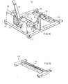
- Figs. 7 and 8 schematically show the lever 75 of the device.l in the low and the high position respectively.
- the point of engagement 77 of the hoisting cable 5 is located considerably below the bearing 76 and the point of engagement 79 of the jack 74 is located substantially at the same distance from its end 80 connected with the frame as the bearing 76.
- Figs. 2 to 4 illustrate a potential method of depositing a stack of objects to be displaced on the supporting structure of a device embodying the invention.
- these objects are bags or bales.
- the stack 40 of bags is supplied on a pallet 41 with the aid of a fork lift truck 42.
- This fork lift truck is provided with a tilting device 43 comprising a supporting plate 44 and a side support 45.
- the supporting plate 44 is moved into contact with the top side of the stack 40.
- the fork carrying the pallet 41 can tilt through 180° together with the supporting plate 44 and the side support 45.
- the stack 40 bears on the supporting plate 44.
- the side support 45 serves to prevent the stack 40 from disengaging during the tilting movement.
- the lowermost stack 40 supported on the supporting plate 44 is pushed off the fork lift truck 42 onto the device 50 embodying the invention by means of a pushing device 46, which basically corresponds with the pushing device described with reference to Fig. 1.
- the fork lift truck 42 is moved for this purpose with the supporting plate 44 as far as to the supporting structure 51 of the device 50.
- the pushing device 46 By subsequently actuating the pushing device 46 the fork lift truck 42 is moved away from the device 50, whilst the supporting plate 44 is drawn away from beneath the stack.
- the pallet 41 remains lying on the fork 53 of the fork lift truck 42 so that it is directly available for reuse.
- the device 50 thus provided with a stack of bags 40 is hoisted with the aid of the hoisting cable 52 to the desired place, where it is pushed off the device with the aid of the pushing device 54 of the device 50.
- a device 55 embodying the invention may be advantageously provided with holding means 61 for retaining a plate-shaped element 59 located beneath the stack 60.
- the stack 60 can be supplied in the same manner as shown in Figs. 2 to 4. On the supporting structure of the device embodying the invention is first deposited such a plate 59 before the stack is deposited on the supporting structure.
- the stack may be supplied already standing on such a plate, whilst with the aid of a fork lift truck with a push-off device it can be directly slipped with the plate onto the device embodying the invention.
- Fig. 5 shows that the device 55 is lowered into a hold 57 of a ship 56. The device 55 is deposited on a layer of bales 58 already lying in the hold 57. By actuating the pushing device 63 of the device 55 the stack 60 is shifted to its place or the device 55 is withdrawn from beneath the stack 60.
- the device 55 When unloading the bales the device 55 is positioned by means of the hoisting cable 64 at the place in front of a stack 60 standing on a plate 59.
- the pushing device 63 is moved by the driving means into its outward position, whilst the plate 59 can fall into a recess 62 on the underside of the pushing member.
- the holding means 61 are actuated so that the plate 59 is clamped tight to the pushing member.
- the driving means of the pushing device 63 are switched on in the opposite sense so that the pushing member is slipped back onto the pushing device 55.
- the plate 59 is thus drawn onto the supporting structure 65.
- the device 55 with the stack 60 standing on it can be lifted by means of the hoisting cable 64 and be conducted out of the hold.
- the device 101 embodying the invention shown in Figs. 9 and 10 comprises a carrying frame 102 with which a push-off device 103 is connected.
- the push-off device 103 comprises piston/cylinder devices 104, which are single-acting cylinders.
- the piston/cylinder connected herewith, but not shown need thus displace only such an amount of fluid as is necessary for pushing out once the piston/ cylinders 104 of the push-off device 103.
- the push-off device 103 is pushed back into its drawn-in position when the stack of objects 107 is deposited on the carrying frame 102.
- the device embodying the invention furthermore comprises a supporting frame 106 in which the carrying frame 102 can be positioned by the lifting device and which retains said carrying frame 102.
- the supporting frame 106 is separately arranged on the loading site 109 and bears on the ground by rubber-clad feet 112.
- the rubber has such a high friction coefficient with respect to the surface of the loading site 109 that the forces involved in depositing the stack of objects 107 on the frame 102 do not cause a shift of the supporting frame.
- Figs. 9 and 10 show that the carrying frame 102 is positioned by the lifting device in the supporting frame 106. Subsequently a stack of objects 107 is supplied on a pallet 108 by means of a fork lift truck 110.
- This fork lift truck 110 is provided with a push-off device 111.
- the operator of the fork lift truck 110 has positioned the pallet 108 in front of the carrying frame 102, he actuates the push-off device 111 so that the stack 107 is shifted from the pallet 108 onto the carrying frame 102.
- the stack 107 pushes the push-off device 103 from the carrying frame 102 back into its drawn-in position.
- the wheel 113 of the carrying frame 102 bears on the guide face l14 of the supporting frame 106 so that the carrying frame 102 is not pushed away by the backward pressure on the pushing device 103.
- Fig. 11 shows in detail that the supporting frame 106 is provided with the above-mentioned carrying frame guide 114 and an opposite guide 115.
- These guides 114 and 115 are converging downwardly. Furthermore lateral guides 116 are provided, which are also converging in a downward direction.
- the carrying frame 102 is lowered into the supporting frame 106, the carrying frame 102 is automatically positioned correctly. In a lateral direction the carrying frame 102 is positioned because side parts of said frame are guided by the lateral guides 116 in a direction of length by the cooperation of the wheels 113 of the carrying frame 102 with the guides 114 and 115.
- the carrying frame guide 114 is formed by a side face of a box-shaped part filled with ballast 117.
- This ballast may be formed by concrete or metal waste or a combination thereof. Owing to the weight of the ballast l17 the maximum frictional force of the flat legs 112 with respect to the loading site is sufficiently high to withstand forces involved in operation.
- Fig. 11 shows that the supporting frame 106 is prolonged to the front and provided at the front with pallet guides 118.
- the pallet guides 118 ensure that the pallet gets in straight line in front of the carrying farme 102. The stack 107 is thus correctly deposited on the carrying frame 102.
- rollers 119 At the front end of the supporting frame 106 are provided guide rollers 119, which support the underside of the stack 107 when it is being shifted from the pallet 108 onto the carrying frame 102.
- the supporting surface 122 of the supporting frame 102 may be serrated so that the teeth snap into the recesses between the rollers 119 of the supporting frame 106.
- Fig. 12 shows an alternative embodiment in which the supporting frame 120 is provided with a single continuous roller 121. The front edge of the supporting surface of the carrying frame of the device can then be straight.
Abstract
Description
- The invention relates to a device for displacing a stack of objects such as boxes or bales comprising a carrying frame, a supporting structure for the stack connected with said frame and forming a carrying surface, a lifting device engaging the carrying frame by a hoisting member, for example a hoisting cable, at a distance above the supporting structure and a push-off device connected with the supporting frame comprising a pushing member movably guided by guide means along the supporting structure and driven by driving means and coming into contact with a side face of the stack.
- Such a device is known from DE-A-1 816 653. Such a device is used, for example, for loading a ship. The objects piled on the supporting surface are pushed by the push-off device from the carrying surface in the ship's hold so that the stack as a whole is deposited in the hold. In this known device the driving means comprise a hydraulic aggregate having a hydraulic pump driven by an electric motor. The electric motor may be fed by electric current supplied externally through a cable or by an electric accumulator arranged in the carrying frame. In the event of external supply of electric current the required electric leads hinder the maniability of the device. The use of an accumulator also has disadvantages. The accumulator has to be periodically charged, for which purpose it has to be removed from the carrying frame and to be replaced by a freshly charged accumulator. Thus the device is temporarily out of use and loading has to be interrupted.
- The invention has for its object to provide a device of the kind set forth in the preamble which does not exhibit said disadvantages.
- In a device embodying the invention this is achieved in that the lifting member engages an engaging member, connected with the frame so as to be movable between a high and a low position and coupled with energy storing means receiving energy at least during a movement from the low to the high position. Thus electric or hydraulic ducts from the outside or a charging apparatus for charging an accumulator are not required. The energy for the driving means is obtained from a free stroke of the lifting member with respect to the frame. In this way a device is obtained which is fully independent of external energy supply so that it is little vulnerable and easy to use. The device can co-operate with any desired lifting device.
- The energy storing means preferably comprise a hydraulic jack and a hydraulic accumulator coupled with the former. In this way a structurally effective embodiment of the device is obtained, which is resistant to rough handling.
- A further advantageous development of the device embodying the invention is obtained when the engaging member comprises a lever journalled on the frame, the first lever arm being engaged by the lifting member and the second lever arm by the jack, the jack being connected with the lever and the frame in a manner such that in the low position the point of engagement of the lifting member is located considerably below the bearing and the point of engagement of the jack is substantially at the same distance from its end connected with the frame as the bearing, whereas in the high position the point of engagement of the lifting member is located substantially at the same height as the bearing and the point of engagement of the jack is located at a considerably different distance from its end connected with the frame than the bearing. This measure results in that at the beginning of the movement of the engaging member from the low to the high position a small transmission ratio between the movements of the of the lifting member and the jack is obtained. Consequently the higher becomes the pressure of the hydraulic fluid in the jack and the hydraulic accumulator, the higher will be the force exerted on the jack. In this way a minimum stroke of the engaging member is obtained so that an advantageous, compact construction can be obtained.
- Moreover, by said measure it can be ensured that with an appropriate adjustment of the residual pressure in the hydraulic system the weight of the empty device is not sufficient to cause the engaging member to turn from the low to the high position so that in this situation the point of engagement of the lifting device is located nearer the fulcrum of the lever than in the loaded state of the device, in which the engaging member is in the higher position. In this way it can be ensured that both in the empty and the loaded state of the device the point of engagement of the lifting device is located substantially perpendicularly above the centre of gravity so that the device will invariably hang perpendicularly on the lifting device.
- In order to cause the device to move with minimum resistance across the bottom or the stacked layers of bales or boxes, when the push-off device is actuated, the frame is provided with supporting wheels rotatable about a shaft extending transversely of the direction of movement of the pushing member at the end remote from the supporting structure. During, the pushing-off movement the wheels roll with minimum resistance along the underlying layer.
- In order to limit the required stroke of the engaging member the hydraulic jacks of the push-off device may be single-acting. These hydraulic jacks can indeed push the stack off the carrying surface, but they cannot move back the pushing member. Pushing back the pushing member has then to be performed when the stack of objects is being deposited on the carrying surface. In particular this is done by pushing the stack of objects with the aid of a push-off device from a fork lift truck onto the carrying surface. In order to prevent that the whole device should be pushed away from the fork lift truck by the push-off device rather than only the pushing member thereof, a device in a preferred embodiment of the invention is characterized by a supporting frame that can be separately positioned on a loading site and is provided with supporting means supporting the carrying frame in a direction opposite the pushing-off direction and transferring forces to engaging means on the loading site. Prior to loading the carrying frame is positioned at the supporting frame, which then supplies sufficient counter-pressure for pushing the pushing member back into the rest position.
- In a further development of the device embodying the invention the supporting frame comprises downwardly converging carrying frame guides co-operating with the supporting frame. The carrying frame can thus be moved by the lifting device very rapidly and in the correct position with respect to the supporting frame. The operator of the lifting device only need lower the carrying frame approximately above the supporting frame, the carrying frame guides ensure correct positioning.
- In a further development of the invention the supporting frame comprises rearwardly converging pallet guides at its front end viewed in the pushing-off direction. The stack supplied from a fork lift truck onto a pallet can thus be advantageously and readily positioned in front of the carrying surface, after which the push-off device of the fork lift truck automatically moves the stack correctly onto the carrying surface. This results in the additional advantage that the device embodying the invention can be very rapidly loaded, which enables optimum use of the device.
- Preferably at least one roller rotatable about a horizontal transverse shaft is arranged on the supporting frame at the foremost end viewed in the pushing-off direction. This roller ensures a satisfactory transfer of the stack of objects from the pallet supported by the fork lift truck onto the carrying surface of the device.
- Further features and advantages of the device will become apparent from the following description of embodiments of the invention with reference to the accompanying drawings.
- Fig. 1 is a perspective view of the device embodying the invention, some parts being partly broken away.
- Figs. 2 to 4 illustrate perspectively the deposition of a stack of objects on a device embodying the invention.
- Figs. 5 and 6 are perspective views of the device in a different embodiment of the invention in use.
- Figs. 7 and 8 schematically show the low and the high position respectively of the engaging member of the device shown in Fig. 1.
- Figs. 9 and 10 illustrate in side elevations the deposition of a stack of objects in a different manner on a device embodying the invention.
- Fig. 11 is a fragmentary, perspective view of the supporting frame of the device shown in Figs. 9 and 10.
- Fig. 12 shows a variant of the supporting frame of the device embodying the invention.
- The
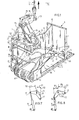
device 1 embodying the invention comprises a carrying frame 2 with which is connected a supportingstructure 3 forming a carrying surface. On the supporting structure 3 a stack of objects such as boxes or bales can be supported in the way to be described more fully with reference to the further Figures. Thedevice 1 furthermore comprises a lifting device 4 formed in this embodiment by a hoisting crane (not shown), the lifting member of which formed by a hoistingcable 5 is coupled with thedevice 1. - With the frame 2 is connected a push-off
device 6. The push-offdevice 6 comprises a pushing member 7 which is adapted to move on the supportingstructure 3. During this movement the pushing member 7 is guided by guide means. These guide means compriseguide tracks 10 in the supportingstructure 3, along which skids 11 of the pushing member can slide. The pushing member 7 is held in a vertical position by aguide arm 15 comprising two plates 16 and 18 pivoted to one another at 17. The plates 16 and 18 are connected by means ofhinges beams hinges guide arm 15. The pushingplate 6 is engaged on both sides insupports 14 by two sectional pushingarms 12. At their ends near the frame 2 the pushingarms 12 are each rigidly connected with ashaft 13 journalled in the frame 2. Owing to the rigid connection of the pushingarms 12 with theshaft 13 the pushingplate 6 is prevented from getting out of square. - Below the pushing member 7 has a
recess 68 into which can extend a supporting, plate-shaped member. With the pushing member 7 are furthermore connectedholding means 69 capable of retaining the plate-shaped member. The operation of these parts will become apparent from the description of Figs. 5 and 6. - The lifting member formed by the hoisting
cable 5 engages an engaging member formed by alever 75. Thislever 75 is pivotally mounted in the carrying frame 2 by means of abearing 76 and can move between a high and a low position. The end of thelever 75 opposite theengaging point 77 of the hoisting cable 78 is engaged at thepivotal point 79 by ahydraulic jack 74. Thejack 74 has pivoted itsother end 80 to the frame 2. Thehydraulic jack 74 is coupled through ducts on the one hand with areservoir 81 of hydraulic fluid and ahydraulic pressure accumulator 82. When thedevice 1 loaded with a stack of objects is lifted by the hoistingcable 5, first thelever 75 will turn about thebearing 76 before the frame 2 is lifted. The plunger of thejack 74 is pushed inwards and the displaced fluid is pressed into thepressure accumulator 82. In this way an amount of energy is stored, which is sufficient to actuate the push-offdevice 6. When thelever 75 has fully turned into its high position, in which the jack cannot be further pushed inwards or in which thelever 75 strikes a stop, thedevice 1 is lifted. When thedevice 1 is again put down, thelever 75 is turned back from its high position into its low position under the action of the weight of the hoistingcable 5 or with the aid of a spring (not shown). Thejack 74 then draws in hydraulic fluid from thereservoir 81. As a matter of course for these operations the ducts between thereservoir 81, thejack 74 and thepressure accumulator 82 include the appropriate non-return valves. - The pressurized hydraulic fluid in the
accumulator 82 can be supplied through theducts 85 to thehydraulic jacks 86 for driving the push-off device. Theducts 85 include a two-position valve 83 by which an outward or an inward movement of the jack can be optionally actuated. By actuating the control-valve 84 the chosen movement of thejack 86 is started. - The proportions of the jack are chosen so that the displaced volume of hydraulic fluid is largely sufficient for fully pushing out or fully drawing in the
jack 86. Moreover, the proportions are such that the produced pressure in theaccumulator 82 is sufficient for displacing the stack of objects. - By switching the two-
way valve 83 into the drawing-in position for thejack 86 and by opening the control-valve 84 the push-offdevice 6 is automatically drawn back when thedevice 1 is lifted. - Fig. 1 furthermore shows that supporting
wheels 87 are arranged at the end of the frame 2 remote from the supportingstructure 3. These supportingwheels 87 can rotate about ashaft 13, which is transverse of the direction of displacement of the push-offdevice 6. These supportingwheels 87 facilitate drawing thedevice 1 from beneath a positioned stack. - Figs. 7 and 8 schematically show the
lever 75 of the device.l in the low and the high position respectively. In the low position shown in Fig. 7 the point ofengagement 77 of the hoistingcable 5 is located considerably below thebearing 76 and the point ofengagement 79 of thejack 74 is located substantially at the same distance from itsend 80 connected with the frame as thebearing 76. - In the high position of the
lever 75 shown in Fig. 8 the point ofengagement 77 of the lifting member is located substantially at the same height as thebearing 76 and the point ofengagement 79 of thejack 74 is located appreciably nearer theend 80 connected with the frame than thebearing 76. By this design it is ensured that an advantageous difference in leverage is obtained between the beginning of the lifting movement, that is to say, from the low position, and the end of the lifting movement i.e. near the high position. Figs. 7 and 8 clearly show that the ratio of themoment arms work line 90 of the lifting force and the reactive force of thejack 74 respectively is materially lower than the ratio of themoment arms jack 74 the counter-pressure and hence the reactive force increases. By using a lever, the proportions of which satisfy the above-mentioned locations of the respective points of engagement, the lifting effort is utilized to the optimum so that the stroke of the point ofengagement 77 of the lifting force with respect to the frame is at a minimum. - By choosing the residual pressure in the system so high that the weight of the
empty device 1 is not sufficient to turn thelever 75 from the position of Fig. 7 into that of Fig. 8, it can be ensured that thedevice 1 will be hanging in a perpendicular position both in the empty and in the loaded state. In the empty state the centre of gravity of the device is located further to the right than in the loaded state. Figs. 7 and 8 clearly show that the point of engagement of the lifting device is located further to the left in the empty state than in the loaded state. - Figs. 2 to 4 illustrate a potential method of depositing a stack of objects to be displaced on the supporting structure of a device embodying the invention. In these Figs. these objects are bags or bales.
- The
stack 40 of bags is supplied on apallet 41 with the aid of a fork lift truck 42. This fork lift truck is provided with atilting device 43 comprising a supportingplate 44 and aside support 45. The supportingplate 44 is moved into contact with the top side of thestack 40. As is shown in Fig. 3 the fork carrying thepallet 41 can tilt through 180° together with the supportingplate 44 and theside support 45. In the fully tilted situation shown in Fig. 4 thestack 40 bears on the supportingplate 44. Theside support 45 serves to prevent thestack 40 from disengaging during the tilting movement. Thelowermost stack 40 supported on the supportingplate 44 is pushed off the fork lift truck 42 onto thedevice 50 embodying the invention by means of a pushingdevice 46, which basically corresponds with the pushing device described with reference to Fig. 1. The fork lift truck 42 is moved for this purpose with the supportingplate 44 as far as to the supportingstructure 51 of thedevice 50. By subsequently actuating the pushingdevice 46 the fork lift truck 42 is moved away from thedevice 50, whilst the supportingplate 44 is drawn away from beneath the stack. Thepallet 41 remains lying on the fork 53 of the fork lift truck 42 so that it is directly available for reuse. - The
device 50 thus provided with a stack ofbags 40 is hoisted with the aid of the hoisting cable 52 to the desired place, where it is pushed off the device with the aid of the pushingdevice 54 of thedevice 50. - As is shown in Figs. 5 and 6 a
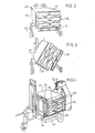
device 55 embodying the invention may be advantageously provided with holding means 61 for retaining a plate-shapedelement 59 located beneath thestack 60. Thestack 60 can be supplied in the same manner as shown in Figs. 2 to 4. On the supporting structure of the device embodying the invention is first deposited such aplate 59 before the stack is deposited on the supporting structure. As an alternative the stack may be supplied already standing on such a plate, whilst with the aid of a fork lift truck with a push-off device it can be directly slipped with the plate onto the device embodying the invention. Fig. 5 shows that thedevice 55 is lowered into ahold 57 of aship 56. Thedevice 55 is deposited on a layer ofbales 58 already lying in thehold 57. By actuating the pushingdevice 63 of thedevice 55 thestack 60 is shifted to its place or thedevice 55 is withdrawn from beneath thestack 60. - When unloading the bales the
device 55 is positioned by means of the hoistingcable 64 at the place in front of astack 60 standing on aplate 59. The pushingdevice 63 is moved by the driving means into its outward position, whilst theplate 59 can fall into arecess 62 on the underside of the pushing member. The holding means 61 are actuated so that theplate 59 is clamped tight to the pushing member. Subsequently the driving means of the pushingdevice 63 are switched on in the opposite sense so that the pushing member is slipped back onto the pushingdevice 55. Theplate 59 is thus drawn onto the supportingstructure 65. Thedevice 55 with thestack 60 standing on it can be lifted by means of the hoistingcable 64 and be conducted out of the hold. - The
device 101 embodying the invention shown in Figs. 9 and 10 comprises a carryingframe 102 with which a push-off device 103 is connected. In order to obtain a simple structure of the hydraulic system of thedevice 101 and to limit the stroke of thelever 105 the push-off device 103 comprises piston/cylinder devices 104, which are single-acting cylinders. At each stroke of thelever 105 the piston/cylinder connected herewith, but not shown need thus displace only such an amount of fluid as is necessary for pushing out once the piston/cylinders 104 of the push-off device 103. The push-off device 103 is pushed back into its drawn-in position when the stack ofobjects 107 is deposited on the carryingframe 102. For this purpose the device embodying the invention furthermore comprises a supportingframe 106 in which the carryingframe 102 can be positioned by the lifting device and which retains said carryingframe 102. The supportingframe 106 is separately arranged on theloading site 109 and bears on the ground by rubber-cladfeet 112. The rubber has such a high friction coefficient with respect to the surface of theloading site 109 that the forces involved in depositing the stack ofobjects 107 on theframe 102 do not cause a shift of the supporting frame. Figs. 9 and 10 show that the carryingframe 102 is positioned by the lifting device in the supportingframe 106. Subsequently a stack ofobjects 107 is supplied on apallet 108 by means of afork lift truck 110. Thisfork lift truck 110 is provided with a push-off device 111. As soon as the operator of thefork lift truck 110 has positioned thepallet 108 in front of the carryingframe 102, he actuates the push-off device 111 so that thestack 107 is shifted from thepallet 108 onto the carryingframe 102. Thestack 107 pushes the push-off device 103 from the carryingframe 102 back into its drawn-in position. Thewheel 113 of the carryingframe 102 bears on the guide face l14 of the supportingframe 106 so that the carryingframe 102 is not pushed away by the backward pressure on the pushingdevice 103. Fig. 11 shows in detail that the supportingframe 106 is provided with the above-mentionedcarrying frame guide 114 and anopposite guide 115. Theseguides frame 102 is lowered into the supportingframe 106, the carryingframe 102 is automatically positioned correctly. In a lateral direction the carryingframe 102 is positioned because side parts of said frame are guided by the lateral guides 116 in a direction of length by the cooperation of thewheels 113 of the carryingframe 102 with theguides - The carrying
frame guide 114 is formed by a side face of a box-shaped part filled withballast 117. This ballast may be formed by concrete or metal waste or a combination thereof. Owing to the weight of the ballast l17 the maximum frictional force of theflat legs 112 with respect to the loading site is sufficiently high to withstand forces involved in operation. Fig. 11 shows that the supportingframe 106 is prolonged to the front and provided at the front with pallet guides 118. When the operator of thefork lift truck 110 is positioning thestack 107 on thepallet 108 in front of the supportingframe 106, the pallet guides 118 ensure that the pallet gets in straight line in front of the carryingfarme 102. Thestack 107 is thus correctly deposited on the carryingframe 102. - At the front end of the supporting
frame 106 are providedguide rollers 119, which support the underside of thestack 107 when it is being shifted from thepallet 108 onto the carryingframe 102. An additional advantage is that potential problems due to height differences by tolerances of the height of thepallet 108 are avoided by therollers 119. - In the embodiment of the supporting
frame 106 shown in Fig. 11 the supportingsurface 122 of the supportingframe 102 may be serrated so that the teeth snap into the recesses between therollers 119 of the supportingframe 106. - Fig. 12 shows an alternative embodiment in which the supporting
frame 120 is provided with a singlecontinuous roller 121. The front edge of the supporting surface of the carrying frame of the device can then be straight.
Claims (9)
Applications Claiming Priority (2)
| Application Number | Priority Date | Filing Date | Title |
|---|---|---|---|
| NL8300017A NL8300017A (en) | 1983-01-04 | 1983-01-04 | DEVICE FOR MOVING A STACK OF OBJECTS SUCH AS BOXES OR BALES. |
| NL8300017 | 1983-01-04 |
Publications (2)
| Publication Number | Publication Date |
|---|---|
| EP0113155A1 true EP0113155A1 (en) | 1984-07-11 |
| EP0113155B1 EP0113155B1 (en) | 1986-10-15 |
Family
ID=19841179
Family Applications (1)
| Application Number | Title | Priority Date | Filing Date |
|---|---|---|---|
| EP19830201867 Expired EP0113155B1 (en) | 1983-01-04 | 1983-12-29 | Device for moving a pile of objects such as boxes or bags |
Country Status (3)
| Country | Link |
|---|---|
| EP (1) | EP0113155B1 (en) |
| DE (1) | DE3366901D1 (en) |
| NL (1) | NL8300017A (en) |
Cited By (7)
| Publication number | Priority date | Publication date | Assignee | Title |
|---|---|---|---|---|
| EP0154159A1 (en) * | 1984-02-10 | 1985-09-11 | Hermann Kruse | Loading device for a crane |
| EP0189969A1 (en) * | 1985-02-01 | 1986-08-06 | Pilkington Plc | Gripper apparatus for stacking a batch of sheets |
| EP0192994A1 (en) * | 1985-02-26 | 1986-09-03 | International Business Machines Corporation | Article manipulator for robot |
| US4789295A (en) * | 1985-02-26 | 1988-12-06 | International Business Machines Corp. | Article manipulator for robot |
| WO1998058871A1 (en) * | 1997-06-24 | 1998-12-30 | Autefa Maschinenfabrik Gmbh | Bale gripper loader for strapped compressed bales |
| US7427185B2 (en) | 1998-06-08 | 2008-09-23 | Stevedoring Services Of America, Inc. | Method and apparatus for loading stacks of cartons of frozen animal products onto vessels using a carrier |
| US7780397B1 (en) * | 2007-06-14 | 2010-08-24 | Coastal Cargo Company, Inc. | Method and apparatus for loading vessels using rotation |
Families Citing this family (2)
| Publication number | Priority date | Publication date | Assignee | Title |
|---|---|---|---|---|
| CN104444958B (en) * | 2014-10-15 | 2017-03-15 | 杭州娃哈哈科技有限公司 | Goods stacking grabber |
| CN104444964B (en) * | 2014-10-15 | 2017-02-22 | 杭州娃哈哈科技有限公司 | Inserting and taking type grabber capable of automatically unloading goods |
Citations (5)
| Publication number | Priority date | Publication date | Assignee | Title |
|---|---|---|---|---|
| DE1816652A1 (en) * | 1968-12-23 | 1970-07-02 | Kilian Kaup Kg Ges Fuer Maschb | Crane lifting gear with a flat load-bearing surface |
| US3655232A (en) * | 1968-06-20 | 1972-04-11 | Ghislain Antoine Jean Marie Ma | Gripper for handling heavy products and specifically horizontal-axis coils |
| AU488095B2 (en) * | 1973-10-30 | 1975-05-01 | B Q P Industries Inc. | Slip pallet |
| FR2249004A1 (en) * | 1973-10-25 | 1975-05-23 | Barra Philippe | Load hoist system using cable suspended forks - uses hydraulic rams to align fork and move it into pallet |
| US4262950A (en) * | 1979-01-08 | 1981-04-21 | Paper Converting Machine Company | Lateral shifting device for crane |
-
1983
- 1983-01-04 NL NL8300017A patent/NL8300017A/en not_active Application Discontinuation
- 1983-12-29 DE DE8383201867T patent/DE3366901D1/en not_active Expired
- 1983-12-29 EP EP19830201867 patent/EP0113155B1/en not_active Expired
Patent Citations (5)
| Publication number | Priority date | Publication date | Assignee | Title |
|---|---|---|---|---|
| US3655232A (en) * | 1968-06-20 | 1972-04-11 | Ghislain Antoine Jean Marie Ma | Gripper for handling heavy products and specifically horizontal-axis coils |
| DE1816652A1 (en) * | 1968-12-23 | 1970-07-02 | Kilian Kaup Kg Ges Fuer Maschb | Crane lifting gear with a flat load-bearing surface |
| FR2249004A1 (en) * | 1973-10-25 | 1975-05-23 | Barra Philippe | Load hoist system using cable suspended forks - uses hydraulic rams to align fork and move it into pallet |
| AU488095B2 (en) * | 1973-10-30 | 1975-05-01 | B Q P Industries Inc. | Slip pallet |
| US4262950A (en) * | 1979-01-08 | 1981-04-21 | Paper Converting Machine Company | Lateral shifting device for crane |
Cited By (9)
| Publication number | Priority date | Publication date | Assignee | Title |
|---|---|---|---|---|
| EP0154159A1 (en) * | 1984-02-10 | 1985-09-11 | Hermann Kruse | Loading device for a crane |
| EP0189969A1 (en) * | 1985-02-01 | 1986-08-06 | Pilkington Plc | Gripper apparatus for stacking a batch of sheets |
| EP0192994A1 (en) * | 1985-02-26 | 1986-09-03 | International Business Machines Corporation | Article manipulator for robot |
| US4789295A (en) * | 1985-02-26 | 1988-12-06 | International Business Machines Corp. | Article manipulator for robot |
| WO1998058871A1 (en) * | 1997-06-24 | 1998-12-30 | Autefa Maschinenfabrik Gmbh | Bale gripper loader for strapped compressed bales |
| US7427185B2 (en) | 1998-06-08 | 2008-09-23 | Stevedoring Services Of America, Inc. | Method and apparatus for loading stacks of cartons of frozen animal products onto vessels using a carrier |
| US7780397B1 (en) * | 2007-06-14 | 2010-08-24 | Coastal Cargo Company, Inc. | Method and apparatus for loading vessels using rotation |
| US8632296B1 (en) * | 2007-06-14 | 2014-01-21 | Coastal Cargo Company, Inc. | Method and apparatus for loading vessels using rotation |
| US9745025B1 (en) | 2007-06-14 | 2017-08-29 | Coastal Cargo Company | Method and apparatus for loading vessels using rotation |
Also Published As
| Publication number | Publication date |
|---|---|
| NL8300017A (en) | 1984-08-01 |
| DE3366901D1 (en) | 1986-11-20 |
| EP0113155B1 (en) | 1986-10-15 |
Similar Documents
| Publication | Publication Date | Title |
|---|---|---|
| US2256454A (en) | Industrial lift truck | |
| CA1302354C (en) | Means for handling containers, load pallets or equivalent, and construction of a container, load pallet or equivalent handled with the means | |
| EP1360140B1 (en) | Cantilevered, self-adjusting pneumatic pallet positioner | |
| EP0113155B1 (en) | Device for moving a pile of objects such as boxes or bags | |
| US5697294A (en) | Device for compressing tires for shipment in containers | |
| US3645409A (en) | Load transfer and pallet stacker | |
| US2682347A (en) | Motorized hand truck with load clamping carrier | |
| US20130195592A1 (en) | Push-Pull Device, Fork-Lift Truck and Method for Displacing Goods | |
| DK2566760T3 (en) | Pallet turntable method for rotating a pallet and the use of a pallet turntable | |
| US2799417A (en) | Power driven material handling truck with stacking mechanism | |
| US6279686B1 (en) | Attachment for flood and yarn trucks with a lift mast, especially for fork lift trucks | |
| US4058225A (en) | Method for loading a layer of goods on a movable supporting means and a pallet loader for carrying out the method | |
| US5582101A (en) | Method of palletizing tube packages utilizing a compression plate to compress the tube packages | |
| US3244291A (en) | Timber-carrying grab for overhead crane | |
| US2785818A (en) | Stripper mechanism for lift trucks | |
| US4526504A (en) | Push-pull de-tiering system | |
| GB2078667A (en) | Loading device | |
| US5102282A (en) | Unit load transfer device and method | |
| US3126223A (en) | kughler | |
| US3426927A (en) | Movable platform with lift and turnover mechanism | |
| US3039632A (en) | Slab laying cart | |
| EP1718558A1 (en) | Apparatus for handling cylindric objects | |
| US3278055A (en) | Means for collectively transferring a plurality of stacked articles | |
| US2576482A (en) | Sheet pallet stacker | |
| GB2160844A (en) | Handling means for unit loads |
Legal Events
| Date | Code | Title | Description |
|---|---|---|---|
| PUAI | Public reference made under article 153(3) epc to a published international application that has entered the european phase |
Free format text: ORIGINAL CODE: 0009012 |
|
| AK | Designated contracting states |
Designated state(s): BE DE FR GB IT NL SE |
|
| 17P | Request for examination filed |
Effective date: 19850114 |
|
| R17P | Request for examination filed (corrected) |
Effective date: 19850111 |
|
| GRAA | (expected) grant |
Free format text: ORIGINAL CODE: 0009210 |
|
| AK | Designated contracting states |
Kind code of ref document: B1 Designated state(s): BE DE FR GB IT NL SE |
|
| PG25 | Lapsed in a contracting state [announced via postgrant information from national office to epo] |
Ref country code: IT Free format text: LAPSE BECAUSE OF FAILURE TO SUBMIT A TRANSLATION OF THE DESCRIPTION OR TO PAY THE FEE WITHIN THE PRESCRIBED TIME-LIMIT;WARNING: LAPSES OF ITALIAN PATENTS WITH EFFECTIVE DATE BEFORE 2007 MAY HAVE OCCURRED AT ANY TIME BEFORE 2007. THE CORRECT EFFECTIVE DATE MAY BE DIFFERENT FROM THE ONE RECORDED. Effective date: 19861015 |
|
| PG25 | Lapsed in a contracting state [announced via postgrant information from national office to epo] |
Ref country code: SE Effective date: 19861031 |
|
| REF | Corresponds to: |
Ref document number: 3366901 Country of ref document: DE Date of ref document: 19861120 |
|
| ET | Fr: translation filed | ||
| PLBE | No opposition filed within time limit |
Free format text: ORIGINAL CODE: 0009261 |
|
| STAA | Information on the status of an ep patent application or granted ep patent |
Free format text: STATUS: NO OPPOSITION FILED WITHIN TIME LIMIT |
|
| 26N | No opposition filed | ||
| BERE | Be: lapsed |
Owner name: SELECTIEBEDRIJF KOOI BEHEER B.V. Effective date: 19901231 |
|
| BERR | Be: reestablished | ||
| PGFP | Annual fee paid to national office [announced via postgrant information from national office to epo] |
Ref country code: GB Payment date: 19960119 Year of fee payment: 13 |
|
| PGFP | Annual fee paid to national office [announced via postgrant information from national office to epo] |
Ref country code: BE Payment date: 19960124 Year of fee payment: 13 |
|
| PGFP | Annual fee paid to national office [announced via postgrant information from national office to epo] |
Ref country code: FR Payment date: 19960126 Year of fee payment: 13 |
|
| PGFP | Annual fee paid to national office [announced via postgrant information from national office to epo] |
Ref country code: NL Payment date: 19960129 Year of fee payment: 13 |
|
| PGFP | Annual fee paid to national office [announced via postgrant information from national office to epo] |
Ref country code: DE Payment date: 19960131 Year of fee payment: 13 |
|
| PG25 | Lapsed in a contracting state [announced via postgrant information from national office to epo] |
Ref country code: GB Effective date: 19961229 |
|
| PG25 | Lapsed in a contracting state [announced via postgrant information from national office to epo] |
Ref country code: BE Effective date: 19961231 |
|
| BERE | Be: lapsed |
Owner name: SELECTIEBEDRIJF KOOI BEHEER B.V. Effective date: 19961231 |
|
| PG25 | Lapsed in a contracting state [announced via postgrant information from national office to epo] |
Ref country code: NL Effective date: 19970701 |
|
| GBPC | Gb: european patent ceased through non-payment of renewal fee |
Effective date: 19961229 |
|
| PG25 | Lapsed in a contracting state [announced via postgrant information from national office to epo] |
Ref country code: FR Effective date: 19970829 |
|
| NLV4 | Nl: lapsed or anulled due to non-payment of the annual fee |
Effective date: 19970701 |
|
| PG25 | Lapsed in a contracting state [announced via postgrant information from national office to epo] |
Ref country code: DE Effective date: 19970902 |
|
| REG | Reference to a national code |
Ref country code: FR Ref legal event code: ST |