EP0112993B1 - Ejection seat stabilization apparatus - Google Patents
Ejection seat stabilization apparatus Download PDFInfo
- Publication number
- EP0112993B1 EP0112993B1 EP83110867A EP83110867A EP0112993B1 EP 0112993 B1 EP0112993 B1 EP 0112993B1 EP 83110867 A EP83110867 A EP 83110867A EP 83110867 A EP83110867 A EP 83110867A EP 0112993 B1 EP0112993 B1 EP 0112993B1
- Authority
- EP
- European Patent Office
- Prior art keywords
- seat
- fins
- fin
- aircraft
- deployed position
- Prior art date
- Legal status (The legal status is an assumption and is not a legal conclusion. Google has not performed a legal analysis and makes no representation as to the accuracy of the status listed.)
- Expired
Links
- 230000006641 stabilisation Effects 0.000 title description 4
- 238000011105 stabilization Methods 0.000 title description 4
- 230000000087 stabilizing effect Effects 0.000 claims description 8
- 230000001154 acute effect Effects 0.000 claims description 5
- 230000008878 coupling Effects 0.000 claims 1
- 238000010168 coupling process Methods 0.000 claims 1
- 238000005859 coupling reaction Methods 0.000 claims 1
- 239000002775 capsule Substances 0.000 description 1
- 230000000052 comparative effect Effects 0.000 description 1
- 230000006835 compression Effects 0.000 description 1
- 238000007906 compression Methods 0.000 description 1
- 231100001261 hazardous Toxicity 0.000 description 1
- 230000000977 initiatory effect Effects 0.000 description 1
- 238000000034 method Methods 0.000 description 1
- 238000012986 modification Methods 0.000 description 1
- 230000004048 modification Effects 0.000 description 1
- 230000010355 oscillation Effects 0.000 description 1
- 230000000149 penetrating effect Effects 0.000 description 1
- 230000009894 physiological stress Effects 0.000 description 1
- 230000002441 reversible effect Effects 0.000 description 1
- 238000000926 separation method Methods 0.000 description 1
- 238000012163 sequencing technique Methods 0.000 description 1
- 230000004083 survival effect Effects 0.000 description 1
Images


Classifications
-
- B—PERFORMING OPERATIONS; TRANSPORTING
- B64—AIRCRAFT; AVIATION; COSMONAUTICS
- B64D—EQUIPMENT FOR FITTING IN OR TO AIRCRAFT; FLIGHT SUITS; PARACHUTES; ARRANGEMENT OR MOUNTING OF POWER PLANTS OR PROPULSION TRANSMISSIONS IN AIRCRAFT
- B64D25/00—Emergency apparatus or devices, not otherwise provided for
- B64D25/08—Ejecting or escaping means
- B64D25/10—Ejector seats
Definitions
- This invention relates to stabilizing apparatus for a seat of the type which can be ejected from an aircraft and which is designed to be lowered to the earth by a parachute, and particularly to stabilizing means operative during the interval between ejection and full parachute deployment.
- the most effective and acceptable system thus uses the seat itself to carry the pilot (or other occupant) out of the aircraft after which the pilot or, in some systems the seat and pilot, are lowered by parachute to safety.
- Such systems have become quite reliable and greatly enhance the safe survival chances of an occupant who finds himself in an aircraft no longer able to fly, but they still subjectthe occupant to physiological stresses and, because of the erratic movement of the seat after it has been suddenly introduced into the airstream outside of the aircraft, can also put undesirable strains on the equipment.
- the air immediately adjacent the sides of the ejected seat normally is very turbulent and does not result in a smooth air flow over a control surface, and the vertical tail surfaces will tend to encounter only this turbulent air during small yaw rotation, so that these vertical surfaces will tend to be ineffective as yaw control surfaces.
- an object of the present invention is to provide an improved stabilization apparatus for an ejection seat including fins which can be deployed to yaw-stabilize the seat following ejection.
- a further object is to provide a stabilizing fin structure which can be deployed aerodynamically and locked in the deployed position.
- Yet another object is to arrange the fins and drogue such that the attitude of the ejection seat allows the size of the fins to be minimized.
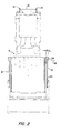
- Fig. 1 shows, in outline, an aircraft seat indicated generally at ten which is of a type designed to be ejected from the aircraft with the occupant seated therein.
- the specific type of seat can vary, and the seat and ejection mechanism itself therefore will not be discussed in detail.
- the seat includes means indicated generally at 11 forming side members which slidably mate with rails attached to the aircraft so that the seat is moveable in the direction of arrow 12.
- the seat normally has means indicated generally at 13 including a rocket propulsion device or the like for propelling the seat along the rails and out of the aircraft.
- a canopy penetrating device 14 At the upper end of the seat structure is a canopy penetrating device 14, a drogue parachute container 15 and a main parachute container 16.
- a control device known as a sequencer controls deployment of the drogue chute and of the main chute at appropriate times, depending upon the speed and altitude of the seat after separation from the aircraft.
- the sequencing is not particularly relevant to the present invention except to note that there is an interval of time between ejection and deployment of the main parachute during which the seat is "flying" and needs to be stabilized.
- the drogue parachute accomplishes some of this stabilizing function, but the seat is still free to rotate about an axis roughly defined by the lines interconnecting the drogue parachute with the seat, and this movement, referred to as yaw, must be controlled.
- the seat is provided with stabilizing fins 20 and 21, the left fin 20 being visible in fig. 1.
- fins 20 and 21 are rotatably mounted so as to be movable through an angle D from their stowed position shown in solid lines to the broken-line deployed position.
- the fins are shaped substantially indentically to each other except that a bend is in the opposite direction in the left fin from the right.
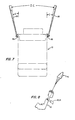
- Left fin 20 is shown separately in Figs. 5 and 6 wherein it will be seen that it has a major portion 23 which is generally trapezoidal in shape with the thickness tapering to a thin edge at the larger end.
- a somewhat smaller inner end portion 24 is bent to form an obtuse angle A with the major portion, this angle preferably being about 85°.
- Fig. 6 also shows mounting holes and a stop shoulder which will be discussed in connection with Figs. 3 and 4.
- Fig. 3 is an enlargement of the upper portion of fin 20 at the rotary connection thereof with the side of seat 10
- Fig. 4 is a side elevation at an angle indicated by arrow 4 in Fig. 3.
- the mounting structure for the left fin includes a base plate 30 one surface of which lies against the substantially vertical side surface of its associated side member of seat 10, and the other surface 34 of which forms an acute angle therewith.
- the angle, illustrated in Fig. 2 as angle B, is preferably 15°.
- a wall 31 is fixedly attached to the outer surface 34 of plate 30 and extends along the front edge thereof and around an upper corner, terminating at a stop surface 32.
- a cylindrical shaft 36 protrudes perpendicularly from surface 34, the shaft having an externally threaded end portion 37 separated from the smooth remaining portion of the shaft by a short portion of reduced diameter.
- Adjacent base plate 30 is a ratchet plate 38 which has a rectangular lower portion including openings to receive screws for attaching the ratchet plate to the side of the seat.
- the upper portion of plate 38 is formed with a series of ratchet teeth 40, each tooth having a face (facing to the right in Fig. 4) which lies along a radius of a circle centered on the central axis of shaft 36. The other face of each tooth lies approximately along the tangent to the tooth peak circle at the peak of the next adjacent tooth.
- a rotatable pawl plate 42 has a central opening which surrounds shaft 36 so that plate 42 is freely rotatable with respect to the shaft.
- the periphery of plate 42 is selected to have a radius slightly smaller than the radius of the peaks of ratchet teeth 40 with respect to the center of shaft 36.
- the end portion 24 of fin 20 is provided with a - plurality of openings 44 which are aligned with similar openings in plate 42 to receive screws, the openings in plate 42 being internally threaded so that the fin can be fixedly attached to, and rotatable with, plate 42.
- Plate 42 is provided with an inwardly extending recess 46 which is generally rectangular in shape and which receives a pawl 48.
- Pawl 48 has a generally rectangular cross-sectional shape and an end surface 49 which is inclined, forming a tip having an acute angle.
- Pawl 48 also has a enlarged portion 50 which fits within recess 46 in relatively close relationship so that the pawl can move in a generally radial direction with respect to pawl plate 42. Pawl 48 is urged radially outwardly by a compression coil spring 52 which is received in a blind bore in pawl 48.
- the radial surface of the pawl tip engages the radial surfaces of each of teeth 40 as the fin moves from its stored toward its deployed position and thereby prevents reverse movement thereof.
- a shoulder 54 formed as a part of end portion 24 of the fin comes in contact with stop surface 32 on wall 31, limiting the movement of the fin to a position such as that shown in Fig. 1.
- the fins are designed and positioned so that they will be contacted and deployed by the airstream passing the seat as it moves in the forward direction (to the left in Fig. 1) as soon as the fins are clear of the cockpit area.
- a positive mechanical deployment apparatus is provided.
- a radially extending pin 60 is mounted in the side of pawl plate 42.
- One end of a lanyard 61 is provided with a loop 62 which surrounds pin 60, the other end of the lanyard being attached firmly to a fixed point within the cockpit (i.e., a point which is not to be ejected).
- the radius on which pin 60 is mounted is about 15° above horizontal.
- the length of lanyard 61 is chosen such that, as soon as the larger ends of fins 20, 21 have cleared the aircraft, the lanyard is straightened to its full length whereupon loop 62 pulls pin 60 downwardly, exerting torque on plate 42 and the fin and at least initiating its movement toward the deployment position. As will be recognized, as soon as fin 60 has rotated to a position somewhat below the horizontal, the eye 62 will slip off of the end of the pin so that the lanyard does not exert any impeding force on further movement of the ejected seat.
- the mounting structure for the right-hand fin is, of course, the same but in mirror image.
- the seat with the fins deployed shows that the fins make an angle of about 15° with a fore-and-aft center line of the seat and about 30° with each other.
- the drogue chute 70 at least partly deployed as seen in Fig. 8, the seat tends to tilt back slightly and is held generally upright, the fins serving to provide the needed yaw stabilization, preventing rotation about the chute lines.
Landscapes
- Business, Economics & Management (AREA)
- Emergency Management (AREA)
- Engineering & Computer Science (AREA)
- Aviation & Aerospace Engineering (AREA)
- Toys (AREA)
- Acyclic And Carbocyclic Compounds In Medicinal Compositions (AREA)
- Seats For Vehicles (AREA)
Applications Claiming Priority (2)
| Application Number | Priority Date | Filing Date | Title |
|---|---|---|---|
| US06/439,933 US4480806A (en) | 1982-11-08 | 1982-11-08 | Ejection seat stabilization apparatus |
| US439933 | 1982-11-08 |
Publications (2)
| Publication Number | Publication Date |
|---|---|
| EP0112993A1 EP0112993A1 (en) | 1984-07-11 |
| EP0112993B1 true EP0112993B1 (en) | 1987-02-25 |
Family
ID=23746736
Family Applications (1)
| Application Number | Title | Priority Date | Filing Date |
|---|---|---|---|
| EP83110867A Expired EP0112993B1 (en) | 1982-11-08 | 1983-10-31 | Ejection seat stabilization apparatus |
Country Status (6)
| Country | Link |
|---|---|
| US (1) | US4480806A (enExample) |
| EP (1) | EP0112993B1 (enExample) |
| JP (1) | JPS59100098A (enExample) |
| DE (1) | DE3369840D1 (enExample) |
| IL (1) | IL69537A (enExample) |
| IN (1) | IN159829B (enExample) |
Families Citing this family (7)
| Publication number | Priority date | Publication date | Assignee | Title |
|---|---|---|---|---|
| US4901951A (en) * | 1988-07-05 | 1990-02-20 | United States Of America As Represented By The Secretary Of The Navy | Yaw fin deployment apparatus for ejection seat |
| AU2003243276A1 (en) * | 2002-05-21 | 2003-12-12 | Atair Aerospace, Inc. | Method and apparatus for delayed parachute deployment |
| US11427339B2 (en) | 2018-12-14 | 2022-08-30 | Goodrich Corporation | Passive head and neck protection canopy piercer |
| US11414197B2 (en) | 2020-04-09 | 2022-08-16 | Ami Industries, Inc. | Airfoil arm restraint systems |
| US11572180B2 (en) * | 2020-04-21 | 2023-02-07 | Ami Industries, Inc. | Interior drogue parachute assembly for ejection seats |
| US11845561B2 (en) | 2020-04-24 | 2023-12-19 | Ami Industries, Inc. | Vertical stabilizer for ejection systems |
| US11396359B2 (en) | 2020-08-03 | 2022-07-26 | Ami Industries, Inc. | Deployable overhead protection assembly and methods of use for canopy fragilization system |
Family Cites Families (26)
| Publication number | Priority date | Publication date | Assignee | Title |
|---|---|---|---|---|
| US2552181A (en) * | 1946-05-24 | 1951-05-08 | Douglas Aircraft Co Inc | Ejecting device |
| US2527020A (en) * | 1947-07-10 | 1950-10-24 | Martin James | Ejection seat for aircraft |
| US2541087A (en) * | 1949-10-25 | 1951-02-13 | Musser Clarence Walton | Safety device for catapulting passengers from aircraft |
| US2702680A (en) * | 1951-02-23 | 1955-02-22 | Edward H Heinemann | Pilot's escape capsule |
| US2806666A (en) * | 1951-06-12 | 1957-09-17 | Boeing Co | Pilot seat and escape means |
| FR1046093A (fr) * | 1951-12-03 | 1953-12-03 | Dispositif mécanique permettant l'expulsion du pilote de cert?oins avions en vol | |
| US2755042A (en) * | 1954-12-10 | 1956-07-17 | Henry A Paddon | Ejection seat catapult |
| US2977080A (en) * | 1955-05-04 | 1961-03-28 | Zborowski Helmut Ph G A R Von | Aircraft having a detachable cabin |
| US2829850A (en) * | 1956-11-13 | 1958-04-08 | Lockheed Aircraft Corp | Aircraft ejection seat |
| US2931598A (en) * | 1956-11-14 | 1960-04-05 | Boeing Co | Ejection seat for aircraft |
| US2941764A (en) * | 1957-08-08 | 1960-06-21 | Electronics Corp America | Flaps for supersonic aircraft escape systems |
| US3042347A (en) * | 1958-01-27 | 1962-07-03 | Ling Temco Vought Inc | Emergency ejection seat |
| US2947503A (en) * | 1958-05-09 | 1960-08-02 | North American Aviation Inc | Ejection seat for aircraft and the like |
| US3015462A (en) * | 1960-02-01 | 1962-01-02 | William H Simmons | Stabilization boom for aircraft encapsulated seat |
| US3063375A (en) * | 1960-05-19 | 1962-11-13 | Wilbur W Hawley | Folding fin |
| US3127838A (en) * | 1960-10-12 | 1964-04-07 | Bombrini Parodi Delfino Spa | Retractable blade tail unit for projectiles |
| US3027126A (en) * | 1961-02-14 | 1962-03-27 | North American Aviation Inc | Ejection seat for aircraft |
| US3067973A (en) * | 1961-03-15 | 1962-12-11 | Donald J Halsey | Ejectable flight capsule |
| US3374965A (en) * | 1967-01-31 | 1968-03-26 | Alexander T. Deutsch | Escape capsule |
| US3679157A (en) * | 1970-10-16 | 1972-07-25 | Us Navy | Aircrew recovery system |
| US3662978A (en) * | 1970-10-22 | 1972-05-16 | Kaman Aerospace Corp | Aircraft ejection seat vehicle stowed rotor |
| IL39260A (en) * | 1972-04-21 | 1975-06-25 | Bouchnik J | Detachable cabin aircraft |
| US4135687A (en) * | 1972-08-10 | 1979-01-23 | Jones Jr Allen | Steering and stabilization apparatus for aircraft |
| US4057206A (en) * | 1975-06-16 | 1977-11-08 | Stencel Aero Engineering Corporation | Ejection sequencing system with airspeed and altitude sensing |
| US4261535A (en) * | 1979-10-05 | 1981-04-14 | The United States Of America As Represented By The Secretary Of The Air Force | Streamline afterbody for an ejection seat |
| US4319723A (en) * | 1980-01-10 | 1982-03-16 | The United States Of America As Represented By The Secretary Of The Air Force | Stabilizer for an ejection seat |
-
1982
- 1982-11-08 US US06/439,933 patent/US4480806A/en not_active Expired - Lifetime
-
1983
- 1983-08-19 IN IN568/DEL/83A patent/IN159829B/en unknown
- 1983-08-22 IL IL69537A patent/IL69537A/xx unknown
- 1983-10-31 EP EP83110867A patent/EP0112993B1/en not_active Expired
- 1983-10-31 DE DE8383110867T patent/DE3369840D1/de not_active Expired
- 1983-11-08 JP JP58209757A patent/JPS59100098A/ja active Granted
Also Published As
| Publication number | Publication date |
|---|---|
| IL69537A (en) | 1988-06-30 |
| JPH0365320B2 (enExample) | 1991-10-11 |
| IN159829B (enExample) | 1987-06-06 |
| EP0112993A1 (en) | 1984-07-11 |
| JPS59100098A (ja) | 1984-06-09 |
| US4480806A (en) | 1984-11-06 |
| DE3369840D1 (en) | 1987-04-02 |
Similar Documents
| Publication | Publication Date | Title |
|---|---|---|
| US4676457A (en) | Aircraft emergency landing system | |
| US2829850A (en) | Aircraft ejection seat | |
| US11103392B2 (en) | Safety system for aerial vehicles and method of operation | |
| US3796398A (en) | In-flight aircraft recovery system | |
| US3721408A (en) | Variable mode sling for helicopter recovery systems | |
| US3999728A (en) | Escape vehicle with fly-away capability | |
| US3606212A (en) | Emergency earth orbital escape device | |
| US3726499A (en) | Method of deploying a parachute by a rocket under low speed conditions | |
| EP0112993B1 (en) | Ejection seat stabilization apparatus | |
| US4580746A (en) | Capsule and rocket extraction system | |
| US4666105A (en) | Unmanned aircraft | |
| US4846421A (en) | Adaptive control system for crew escape devices | |
| US3083938A (en) | Ejection seat and personnel separation device | |
| US5673873A (en) | Rescue system for aircraft | |
| US4040583A (en) | Methods and apparatus for effecting recovery of a high speed aircraft from a condition of incipient or developed spin | |
| US3372893A (en) | Air to ground descent means | |
| US3838940A (en) | Deployable rotor | |
| US3861625A (en) | Ejected pilot stabilizing, retarding, separating and parachute deployment sub-system | |
| US20050087652A1 (en) | Emergency parachute system for helicopters | |
| US4538778A (en) | Dual towline spin-recovery device | |
| US3117744A (en) | Rotary wing alighting devices | |
| US20230174242A1 (en) | Airdrop azimuth control system | |
| US3807671A (en) | Escape and recovery system | |
| US3214118A (en) | Aircraft ejection seats | |
| US4470565A (en) | Yaw stabilization for aircraft ejection seats |
Legal Events
| Date | Code | Title | Description |
|---|---|---|---|
| PUAI | Public reference made under article 153(3) epc to a published international application that has entered the european phase |
Free format text: ORIGINAL CODE: 0009012 |
|
| AK | Designated contracting states |
Designated state(s): DE FR GB IT SE |
|
| 17P | Request for examination filed |
Effective date: 19840713 |
|
| ITF | It: translation for a ep patent filed | ||
| GRAA | (expected) grant |
Free format text: ORIGINAL CODE: 0009210 |
|
| AK | Designated contracting states |
Kind code of ref document: B1 Designated state(s): DE FR GB IT SE |
|
| REF | Corresponds to: |
Ref document number: 3369840 Country of ref document: DE Date of ref document: 19870402 |
|
| ET | Fr: translation filed | ||
| PLBE | No opposition filed within time limit |
Free format text: ORIGINAL CODE: 0009261 |
|
| STAA | Information on the status of an ep patent application or granted ep patent |
Free format text: STATUS: NO OPPOSITION FILED WITHIN TIME LIMIT |
|
| 26N | No opposition filed | ||
| ITPR | It: changes in ownership of a european patent |
Owner name: CESSIONE;UNIRSAL PROPULSION COMPANY INC. |
|
| REG | Reference to a national code |
Ref country code: FR Ref legal event code: TP |
|
| ITTA | It: last paid annual fee | ||
| REG | Reference to a national code |
Ref country code: GB Ref legal event code: 732 |
|
| EAL | Se: european patent in force in sweden |
Ref document number: 83110867.5 |
|
| PGFP | Annual fee paid to national office [announced via postgrant information from national office to epo] |
Ref country code: DE Payment date: 19961108 Year of fee payment: 14 |
|
| PG25 | Lapsed in a contracting state [announced via postgrant information from national office to epo] |
Ref country code: DE Free format text: LAPSE BECAUSE OF NON-PAYMENT OF DUE FEES Effective date: 19980701 |
|
| PGFP | Annual fee paid to national office [announced via postgrant information from national office to epo] |
Ref country code: GB Payment date: 20001013 Year of fee payment: 18 Ref country code: FR Payment date: 20001013 Year of fee payment: 18 |
|
| PGFP | Annual fee paid to national office [announced via postgrant information from national office to epo] |
Ref country code: SE Payment date: 20001016 Year of fee payment: 18 |
|
| PG25 | Lapsed in a contracting state [announced via postgrant information from national office to epo] |
Ref country code: GB Free format text: LAPSE BECAUSE OF NON-PAYMENT OF DUE FEES Effective date: 20011031 |
|
| PG25 | Lapsed in a contracting state [announced via postgrant information from national office to epo] |
Ref country code: SE Free format text: LAPSE BECAUSE OF NON-PAYMENT OF DUE FEES Effective date: 20011101 |
|
| REG | Reference to a national code |
Ref country code: GB Ref legal event code: IF02 |
|
| GBPC | Gb: european patent ceased through non-payment of renewal fee |
Effective date: 20011031 |
|
| PG25 | Lapsed in a contracting state [announced via postgrant information from national office to epo] |
Ref country code: FR Free format text: LAPSE BECAUSE OF NON-PAYMENT OF DUE FEES Effective date: 20020628 |
|
| EUG | Se: european patent has lapsed |
Ref document number: 83110867.5 |
|
| REG | Reference to a national code |
Ref country code: FR Ref legal event code: ST |