EP0112980A2 - Applicateur de pinces hémostatiques activé par un ressort - Google Patents
Applicateur de pinces hémostatiques activé par un ressort Download PDFInfo
- Publication number
- EP0112980A2 EP0112980A2 EP83109885A EP83109885A EP0112980A2 EP 0112980 A2 EP0112980 A2 EP 0112980A2 EP 83109885 A EP83109885 A EP 83109885A EP 83109885 A EP83109885 A EP 83109885A EP 0112980 A2 EP0112980 A2 EP 0112980A2
- Authority
- EP
- European Patent Office
- Prior art keywords
- clip
- magazine
- main body
- coupled
- clips
- Prior art date
- Legal status (The legal status is an assumption and is not a legal conclusion. Google has not performed a legal analysis and makes no representation as to the accuracy of the status listed.)
- Granted
Links
Images


Classifications
-
- A—HUMAN NECESSITIES
- A61—MEDICAL OR VETERINARY SCIENCE; HYGIENE
- A61B—DIAGNOSIS; SURGERY; IDENTIFICATION
- A61B17/00—Surgical instruments, devices or methods, e.g. tourniquets
- A61B17/12—Surgical instruments, devices or methods, e.g. tourniquets for ligaturing or otherwise compressing tubular parts of the body, e.g. blood vessels, umbilical cord
- A61B17/128—Surgical instruments, devices or methods, e.g. tourniquets for ligaturing or otherwise compressing tubular parts of the body, e.g. blood vessels, umbilical cord for applying or removing clamps or clips
Definitions
- a Hemostatic Clip Applicator for the strangulation of tubular members in a rapid and automatic manner is disclosed. That application is directed, in part, to a device having a main body, a clip cartridge, actuating handles, and clip deforming jaws. Disposed within the clip cartridge are a plurality of hemostatic clips, and a clip feed means which moves clips to the clip deforming jaws where the clips are deformed about a blood vessel or the like.
- While the applicator noted in the preceding paragraph provides a novel method for automatically closing blood vessels and other fluid ducts, it requires the manual feeding of a hemostatic clip into the deforming jaws by the forward movement of one of two handles. That is, to operate that device, the surgeon must first move one of the handle portions to a forward position so as to load a hemostatic clip in the deforming jaws, and then return that handle portion to its neutral position. Once the surgeon has located the hemostatic clip around the tubular member to be closed, he squeezes both handle portions together resulting in the crimping of a clip about the blood vessel. When the surgeon is ready to close another blood vessel, this same sequence of moving one handle portion forward and then rearward must be repeated so as to sequentially load and close a clip.
- an alternative hemostatic clip applicator which also provides for the rapid and automatic strangulation of tubular members. That application is directed, in part, to a device in which energy is first stored and then released to automatically deliver a clip into the jaws of the instrument.
- a clip is almost instantaneously delivered to the jaws of the instrument by the release of energy stored in a spring. Then, simply by moving the finger loops toward one another, the clip which has been loaded in the jaw portions can be deformed around a blood vessel or the like. Simultaneously with this crimping of the hemostatic clip, the instrument is again storing energy in the spring so that when another clip is needed, it can be readily available.
- the pawl is prevented from moving backward by the frictional engagement of two side arms disposed on either side of the pawl with the magazine housing walls.
- This frictional engagement of the pawl sidearms must be overcome by the spring in order to drive the pawl and consequently, the clips, forward. Since the force necessary to cock the spring increases the force necessary to close the finger loops and crimp the clip, it is desirable to minimize the requisite strength of the spring to minimize the cocking force of the spring.
- the invention relates to the field of devices useful in the application of hemostatic clips, and more specifically, to devices for the application of hemostatic clips used in the strangulation of blood vessels and other fluid ducts.
- the Jarvik device has a channel in the main body of the instrument which is integral with one of the jaws of the instrument.
- a clip pusher moves the lower most clip in a clip stack through the channel in the main body to the jaws at the far end of the instrument.
- the pusher does not enter the jaws of the Jarvik instrument, but merely abuts the aft-most portion of the jaws without sliding therebetween.
- the jaws of the instrument are approximately the same length as the length of the clips, which can reduce visibility for the surgeon.
- the Jarvik patent does not disclose an instrument which utilizes a spring loaded mechanism so as to move rapidly and accurately a clip from an internal clip magazine to the jaw portions of the instrument.
- a hemostatic clip applicator device useful for rapidly and automatically applying clips for the strangulation of blood vessels and the like has a clip magazine coupled to the exterior of a main'body, the clip magazine being adapted to hold a plurality of hemostatic clips. Attached to one end of the main body are clip deforming jaws adapted to hold and crimp a hemostatic clip about a blood vessel. Slideably disposed within the clip magazine is a clip feed means which is adapted to move clips from the magazine to the clip deforming jaws.
- the clip magazine has a clip loading means which sequentially loads the clip feed means with hemostatic clips from the magazine. Coupled to the clip feed means, the clip loading means and the clip deforming jaws is an actuating means.
- the actuating means includes handle portions coupled to the main body and an energizing means coupled to the main body, the clip feed means, the clip loading means and the handle portions.
- the energizing means is adapted to store energy and selectively supply that energy to the clip feed means and clip loading means.
- the energizing means is activated to supply the stored energy to the clip feed means so as to cause one of the clips stored in the clip magazine to be moved rapidly to the clip deforming jaws.
- the stored energy is also supplied to the clip loading means such that the next clip in the magazine is advanced for loading to the clip feed means.
- the clip can be crimped about a blood vessel or the like simply by moving the handle portions toward one another.
- energy is again stored in the energizing means so as to be available for a subsequent rapid placement of the next clip in the deforming jaws.
- This sequence of rapidly feeding clips to the clip deforming jaws and crimping them may be repeated until the plurality of clips located in the clip magazine is depleted.
- the present invention reduces the force necessary to squeeze the handle portions together, by which the clips are crimped in the clip deforming jaws and the energy is stored in the energizing means. This is accomplished by reducing the friction exerted by the clip loading means, which must be overcome by the energizing means to effectuate the loading of a clip. As a result, the force required to be exerted by the energizing means and, consequently, the energy required to be stored by the energizing means, are correspondingly reduced.
- the improved clip loading means includes a pair of ratchet bars in which one bar is moved in a reciprocating motion relative to the other by the energizing means.
- a pawl means is provided between the ratchet bars, which is adapted to alternately engage the ratchet bars in conjunction with the reciprocating motion of the ratchet bars to advance the clips held within the magazine.
- the force necessary to squeeze the handle portions together is also reduced by an improved energizing means.
- the energizing means includes a camming surface coupled to one of the handle portions and a low friction cam follower coupled to an energy storage means such as a spring. As the handle portions are squeezed together, the camming surface engages the cam follower which causes energy to be stored in the energy storage means in a particularly low friction manner.
- a spring activated hemostatic clip applicator device which is useful in rapidly applying a sequence of hemostatic clips about blood vessels and other fluid ducts.
- The.hemostatic clip applicator of the present invention may be used with hemostatic clips such as is described in our U. S. Patent No. 4,188,953 issued on February 19, 1980, entitled “Hemostatic Clip”, or with any other suitably adapted hemostatic clip.
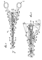
- the spring activated hemostatic clip applying device 2 of the present invention is shown with its actuating means in its "cocked" configuration.
- the actuating means is comprised of an energizing means, and handle portions.
- the energizing means is comprised of ratchet connecting rod or member 50, ratchet spring 58, and latch 54.
- the handle portions are comprised of an upper finger loop 4 and upper finger loop member 5, along with lower finger loop 6 and lower finger loop.member 7.
- Upper finger loop 4 and upper finger loop member 5 are integral with main body 20.
- clip feed blade 18 is a clip feed means which in the presently preferred embodiment is a blade member adapted to slide rapidly through clip magazine means 102 and into the forward portions (i.e., those portions to the left in FIGURE 1) of device 2. Also, as will be described more fully hereinbelow, the rapid movement of clip feed blade 18 into the forward portions of device 2, and the corresponding movement of a hemostatic clip into the jaw members 32, 34 of device 2, is accomplished merely by activating the energizing means of the present invention.
- clip magazine means 102 Disposed within clip magazine means 102 are a plurality of hemostatic clips 37 (FIGURE 9), and magazine 102 is adapted such that the individual clips are available to be moved forward by clip feed blade 18.
- Spring guide means 100 aids the movement of a clip from magazine 102 into the main body 20 of instrument 2.
- a clip deforming means adapted to deform a hemostatic clip 37 about a blood vessel or the like.
- the clip deforming means is comprised of upper jaw portion 32 and lower jaw portion 34.
- Upper jaw portion 32 is fixedly coupled to lower finger loop member 7 and pivotally coupled to main body 20 by upper jaw pivot 36, while lower jaw portion 34 is fixedly coupled to main body 20.
- the clip may be squeezed about a blood vessel by squeezing finger loops 6 and 4 together so that upper jaw portion 32 closes toward lower jaw portion 34.
- ratchet member 50 is coupled to clip feed blade 18 by means of ratchet member pin 17 inserted into slot 23 of clip feed blade 18.
- the ratchet connecting member 50 is also coupled to lower finger loop 6 by cam follower 62 at the end of the ratchet connecting member.
- the ratchet connecting member 50 is slidably carried in a longitudinal groove 25 defined by cover plate 22 and main body 20 when assembled as indicated in FIGURE 3.
- the main body 20 has a window 27 through which the cam follower 62 extends.
- the lower finger loop member 7 includes recess 29 which defines the camming surface 26.
- the cam follower 62 of ratchet connecting member 50 extends into this recess 29 from window 27 of main body 20.
- One end of ratchet spring 58 is coupled to main body 20 by pin 60 of cover plate 22, while the other end is coupled to ratchet connecting member 50 by slot 24.
- Ratchet spring 58 is carried in a groove 31 defined by cover plate 22 and ratchet connecting member 50 when assembled.
- ratchet spring 58 is a helical spring, although other types of springs could be readily utilized.
- the forward advance of clip feed blade 18 and the ratchet member 50 is controlled and fixed by the abutment of the cam follower 62 with the forward portion of cam surface 26 indicated at 28.
- the rearward reach of clip feed blade 18 is controlled by the abutment of rearward stop 16 of lower ratchet bar 110, with end tab 13 of magazine 102.
- FIGURE 2 Illustrated in FIGURE 2 is the relationship of recess 29, cam follower 62, and the window 27 in main body 20.
- lower finger loop 6 is free to travel inwardly and outwardly about pivot 36 within the confines of the travel of cam follower 62 within the recess 29 of lower finger loop member 7.
- This freedom of movement of lower finger loop 6, and the.corresponding freedom of movement of upper jaw portion 32 with respect to lower jaw portion 34 has the following very useful advantage during a surgery.
- cam follower 62 is free to move through window 27 in main body 2 when the latch 54 is released.
- cam follower 62 can freely travel from right to left in window 27.
- FIGURE 4 is an enlarged view of the cam follower 62 at the rearward end of the ratchet connecting member 50.
- cam follower 62 has an axle 46 on which is rotationally carried a roller wheel 47. Coupling wheel 47 to axle 46 is a plurality of roller bearings 48..As will be seen more clearly below, the cam follower 62 of the energizing means reduces the friction which occurs as the spring 58 is cocked, thereby easing the force required to squeeze the finger loops together.
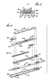
- FIGURE 5 illustrates in greater detail the components comprising the clip magazine 102 and the clip feeding means of the present invention.
- Clip magazine 102 is comprised of a magazine housing 114, containing a plurality of hemostatic clips 37. Located within clip magazine housing 114 is lower ratchet bar 110 and clip feed blade 18 between housing 114 and lower ratchet bar 110.
- Magazine housing 114 is affixed to main body 20 in a cavity 72 (FIGURE 7) which has recesses 74a and 74b on either side. Magazine 102 further includes upper ratchet bar 70 which has a pair of dimpled tabs 76a and 76b which snap into main body recesses 74a and 74b, respectively. In this manner, upper ratchet bar 70 couples the magazine 102 to main body 20.
- pawl 122 is positioned behind the rearward most clip of magazine 102 and is provided to urge the clips forward. As will be more fully explained below, pawl 122 is actuated by the reciprocating forward and backward motion of lower ratchet bar 110 which is in turn moved by clip feed blade 18. As seen more clearly in FIGURE 6, pawl 122 has a downwardly extending resilient tab 78 and an upwardly extending resilient tab 80. The tabs 78 and 80 alternately engage the recesses or holes 82 and 94 of ratchet bars 110 and 70, respectively, to advance the clips 37 forward, in conjunction with the reciprocating motion of the lower ratchet bar 110.
- Completing magazine l02 of the illustrated embodiment is cover bar 96 which is affixed to housing 114 by housing tabs 90 bent over into corresponding recesses 86 of cover bar 96.
- FIGURE 8 is a cross-sectional view of the forward portion of clip applying device 2, as taken along lines 8-8 of FIGURE 1.
- FIGURE 8 it can be seen that there is a groove 40 disposed within upper jaw portion 32.
- Groove 40 in conjunction with the corresponding groove 42 (FIGURE 9) in lower jaw portion 34 serves to guide and secure a hemostatic clip 37 as it is rapidly moved from the main body 20 of instrument 2 to the forward most portions of jaws 32, 34.
- feed blade 18 must be configured so as to be capable of being moved forward through grooves 40 and 42 while simultaneously bending away from main body 20 in grooves 40 and 42.
- this capability has been provided by constructing feed blade 18 of three layers of thin blades of metal in a laminated configuration. The three layers are only coupled at discreet points so that the feed blade 18 is able to move longitudinally through main body 20 while curving around grooves 40 and 42 in jaw portions 32 and 34.
- guide spring means 100 and leaf spring 112 are adapted to maintain clip 37' in its key position 125 until clip 37' is moved forward by feed blade 18.
- the end 140 of upper ratchet bar 70 is adapted to maintain clip 37" in its proper position so that it is available to be moved into key position 125 so as to replace clip 37'.
- the end 140 of upper ratchet bar 70 is bent slightly downward following the taper of housing 114 indicated at 150 (FIGURE 5).
- clip magazine 102 is comprised of a simply constructed housing 114 which is inexpensively stamped from stock material and then attached to the main body 20 by the upper ratchet bar tabs 76.
- clip magazine 102 is replaceably coupled to main body 20 so that when the clips 37 are depleted from magazine 102, that magazine 102 can be removed from instrument 2 and a new magazine 102 can be placed therein.
- FIGURE 8 also shows that lower ratchet bar 110 is coupled to clip feed blade 18 by means of extension member 109 which extends into slot 84 of feed blade 18. Because ratchet connecting member 50 is in its extreme retracted position, extension member 109 is abutting the extreme left end of slot 84. Also disposed within clip housing 114 is pawl 122 with its lower tab 78 disposed just ahead of a lower ratchet bar hole indicated as 82'. The upper pawl tab 80 is disposed in a hole 94' of the upper ratchet bar. Pawl 122 is positioned so as to abut the rearward most clip 37.
- FIGURE 9 is a side cross-sectional view of the forward portion of clip applying device 2 with ratchet connecting member 50 again shown in its extreme retracted position.
- the clip feed blade lost motion slot 84 wherein is disposed extension member 109'of the lower ratchet bar, can be seen more clearly.
- Pawl 122 is shown in its extreme rearward position having tab 78 located just ahead of lower ratchet bar hole 82'.
- the leading edge 124 of pawl 122 is configured so as to conform to the bail portion of clips 37.
- pawl 122 is adapted to move clips 37 forward through magazine 102 when lower ratchet bar 110 is moved forward.
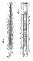
- instrument 2 is illustrated in its configuration just following the spring activated loading of hemostatic clip 37' into jaw portions 32, 34.
- a slight downward movement of finger loop 6 with respect to finger loop 4 causes lower edge 9 of lower finger loop member 7 to abut and thereby rotate latch 54 in a clockwise direction so as to disengage latch 54 from teeth 52 of ratchet member 50.
- the energy stored in ratchet spring 58 causes ratchet member 50 to snap forward, and thereby rapidly move clip feed blade 18 through magazine 102, and ultimately move hemostatic clip 37' into jaw portions 32, 34.
- This rapid forward movement of clip feed blade 18 is brought to an abrupt halt, by the abutment of cam follower 62 with stop surface 28 of camming surface 26 at just the point where clip 37' is properly positioned in jaws 32, 34.
- the forward most end of clip feed blade 18 is split into two sections 21 which are arranged in a forked configuration.
- the abutment of forked ends 21 of clip feed blade 18 with the bail portion of hemostatic clip 37' provides the significant advantage of preventing rearward movement of clip 37' when the clip is being positioned around a blood vessel or the like.
- the forked configuration of the forward most end 21 of clip feed blade 18 has the significant advantage of not reducing visibility through jaw portions 32, 34.
- FIGURE 11 is a cross-sectional view of the forward most section of clip applying device 2, taken along the lines 11-11 of FIGURE 10.
- ratchet connecting member 50 has been moved to its full forward position as in FIGURE 10. Because previous forward movement of ratchet member 50 and feed blade 18 have brought about abutment of low ratchet bar extension member 109 with the rear most end of lost motion slot 84, the further forward movement of clip feed blade 18 has resulted in forward movement of lower ratchet bar 110. This forward movement of lower ratchet bar 110 causes pawl lower tab 78 to drop in and engage hole 82', resulting in forward movement of pawl 122.
- ratchet connecting member 50 has caused clip feed blade 18 to travel through much of upper jaw portion 32 and lower jaw portion 34 and thereby place clip 37 1 at the extreme end of jaw portions 32 and 34.
- this full forward movement of ratchet member 50 has placed a clip in the loaded position in jaw portions 32 and 34 so that it is now ready to be placed about a blood vessel or the like.
- FIGURE 11 It can also be seen in FIGURE 11 that another hemostatic clip 37" has now been moved into the key position 125 so as to be available during the next spring activated loading sequence. It is important to note that clip 37" is resting on platform 116 of lower ratchet bar 110 and is held in place by guide spring 100 and leaf spring 112. Platform l16 prevents one or both legs of clip 37" from becoming disoriented within key position 125. Furthermore the downward taper of upper ratchet bar 70 guides the line of clips down to key position 125 and helps prevent the rearward clips from passing up and over the forward clips as the clips are driven forward. A safety stop 152 at the end of housing 114 prevents the clips from being ejected out of the housing by the forward motion of the lower ratchet bar 110 and pawl 122.
- FIGURE 12 is a cross-sectional side view of clip magazine 102 where, just as in FIGURE 11, connecting member 50 has been brought to its full forward position.
- Cover plate 96 and upper ratchet bar 70 are not shown for clarity...Here, it can be seen that lower ratchet bar extension member 109, which is abutting the right most portion of lost motion slot 84, has now been moved forward by the forward movement of clip feed blade 18. The forward movement of ratchet extension member 109 has caused lower ratchet bar 110 to also move forward. Because lower tab 78 of pawl 122 is disposed in hole 82' of ratchet bar 110, the forward movement of ratchet bar 110 has resulted in the forward movement of pawl 122.
- FIGURE 13 the configuration of spring activated clip applying device 2 while a hemostatic clip 37' is being crimped is illustrated. D ue to the movement of lower finger loop 6 toward upper finger loop 4, and the resulting pivoting of upper jaw portion 32 around pivot 36; upper jaw portion 32 is moved toward lower jaw portion 34 so as to crimp hemostatic clip 37'.
- camming surface 26 engages cam follower 62 so as to cause a retracting force to be applied to cam follower 62 and a corresponding retraction of ratchet member 50. That is, as finger loop 6 is lifted toward finger loop 4, the ratchet connecting member 50 is retracted. This retraction causes a stretching of spring 58 and results in a storage of energy therein.
- cam follower 62 has been shown as a freely spinning wheel, it is recognized that other low friction cam follower devices may be used.
- a fixed surface coated with teflon or other low friction plastics may be used to engage the camming surface 26.
- any forward movement of ratchet member 50 is prevented by the interaction of latch 54 with ratchet member 50. Because the lower edge 9 of lower finger loop member 7 is no longer interacting with latch 54, and because latch spring 56 is causing a counter-clockwise rotational movement of latch 54 about latch pivot 55, latch 54 is caught in one of the various ratchet teeth 52 disposed on the lower edge of ratchet member 50. As ratchet member 50 is retracted, latch 54 rides up and over each of the inclined teeth 52 of ratchet member 50 so as to continue to prevent forward movement of ratchet member 50. Of course, a variety of other mechanisms could be used in place of the ratchet member 50 and latch 54 so as to provide a releasable impediment to movement.
- the lower finger loop member 7 has a tab 154 which overlaps the main body 20 and cover plate 22 to help prevent them from spreading from the lower finger loop member 7 as the finger loops are squeezed together to crimp the clips.
- a similar overhanging tab (not shown) is provided for the same purpose at the other end of lower finger loop member 7 adjacent jaw portions 32 and 34.
- FIGURES 14 and 15 illustrate in greater detail the relationship of feed blade 18, lower ratchet bar 110 and upper ratchet bar 70 when the cocking and crimping motion of instrument 2 is more advanced than the configuration illustrated in FIGURE 13.
- clip feed blade 18 has been moved in the rearward direction by the retracting motion of the ratchet connecting member 50. This rearward movement has caused the forked ends 21 of clip feed blade 18 to retract from jaw portions 32, 34, and the bending of forked ends 21 toward one another as jaw portions 32 and 34 converge.
- lost motion extension member 109 has traveled the length of the lost motion slot 84 contained in feed blade 18. Because lost motion member 109 is a part of lower ratchet bar 110, this rearward movement of extension member 109 through lost motion slot 84 has resulted in little or no rearward movement of lower ratchet bar 110. Of course, the further rearward movement of feed blade 18 has caused a corresponding rearward movement of ratchet bar 110 due to the abutment of lost motion extension member 109 with the forward most section of lost motion slot 84. Ultimately, further rearward movement will be prevented when stop 16 on lower ratchet bar 110 abuts rear stop 13.
- the prevention of additional rearward movement of lower ratchet bar 110 also prevents further rearward movement of feed blade 18 due to the coupling thereof by extension member 109.
- the abutment of stop 16 with stop 13 is designed to coincide with the engagement of the cam follower 62 with the "flat" area 98 (FIGURE 13) of camming surface 26.
- the camming surface 26 is actually curved at a constant radial distance from the pivot point 36 such that the camming surface 26 at 98 no longer acts to retract the ratchet member 50 when the ratchet spring 58 is fully cocked.
- An additional advantage of the "flat" area 98 is that it allows the finger loops 4 and 6 to be further closed to apply additional crimping pressure if necessary on the clip 37' in the jaws 32 and 34, without inducing a further retracting force on the ratchet member 50 after the ratchet spring 58 is fully cocked. This allows variable crimping forces to be applied as needed, yet the spring 58 is fully cocked each time the cam follower 62 reaches the area 98 of camming surface 26.
- pawl 122 has been advanced such that the upper tab 80 is disposed in the upper ratchet bar hole 94" and the lower tab 78 is just ahead of the lower ratchet bar hole 82".
- sequential forward and rearward movement of ratchet bar 110 causes pawl 122 to progressively move forward, from one upper ratchet bar hole 94, to.the next hole 94 and from one lower ratchet bar hole 82 to the next hole 82.
- sequential forward and rearward ratchet bar 110 movement causes the upper pawl tab 80 to engage an upper bar hole 94 during rearward ratchet bar movement alternating with lower pawl tab 78 engagement with a lower ratchet bar hole during forward movement.
- Such progressive movement of pawl 122 causes, in turn, the progressive forward movement of clips 37.
- the improved spring activated clip applying device 2 of the present invention provides an automatic and rapid feeding of hemostatic clips 37 into the jaws of the instrument 2. With only the slightest downward movement of finger loop 6, a clip is almost instanteously delivered to the jaw portions 32, 34. Then, simply by moving finger loops 4 and 6 toward one another, a hemostatic clip 37 which has been loaded in the jaw portions 32, 34 can be deformed around a blood vessel or the like. Simultaneously with this crimping of the hemostatic clip 37, the instrument is again storing energy in a spring so that when another clip is needed, it can be readily available. This process of inward and outward movement of finger loops 4 and 6 may be repeated rapidly, so that one vessel after another is closed by hemostatic clips 37, until the supply of clips in magazine 102 is depleted.
- the clip applying device 2 of the present invention provides the further advantages of high visibility to the user. Because the device 2 is of an extremely thin design, essentially the width of currently used hemostats, and because jaw portions 32 and 34 are curved away from the main body 20, and finally because the clip feed blade 18 is divided into thin forked sections 21 at its extreme end, a surgeon using clip applying device 2 will have a clear view of the vessel he is closing.
- the clip applying device of the present invention closely simulates the feel which is provided by a conventional hemostat in which clips are manually inserted into the jaws of the hemostat.
- Devices which depart radically from the look and feel of conventional manual pliers-like hemostats have met significant resistance on the part of surgeons.
Landscapes
- Health & Medical Sciences (AREA)
- Surgery (AREA)
- Life Sciences & Earth Sciences (AREA)
- Heart & Thoracic Surgery (AREA)
- Nuclear Medicine, Radiotherapy & Molecular Imaging (AREA)
- Vascular Medicine (AREA)
- Engineering & Computer Science (AREA)
- Biomedical Technology (AREA)
- Reproductive Health (AREA)
- Medical Informatics (AREA)
- Molecular Biology (AREA)
- Animal Behavior & Ethology (AREA)
- General Health & Medical Sciences (AREA)
- Public Health (AREA)
- Veterinary Medicine (AREA)
- Surgical Instruments (AREA)
Applications Claiming Priority (2)
| Application Number | Priority Date | Filing Date | Title |
|---|---|---|---|
| US06/433,028 US4522207A (en) | 1981-02-06 | 1982-10-06 | Spring activated hemostatic clip applicator |
| US433028 | 1982-10-06 |
Publications (3)
| Publication Number | Publication Date |
|---|---|
| EP0112980A2 true EP0112980A2 (fr) | 1984-07-11 |
| EP0112980A3 EP0112980A3 (en) | 1986-03-26 |
| EP0112980B1 EP0112980B1 (fr) | 1990-03-07 |
Family
ID=23718570
Family Applications (1)
| Application Number | Title | Priority Date | Filing Date |
|---|---|---|---|
| EP83109885A Expired EP0112980B1 (fr) | 1982-10-06 | 1983-10-04 | Applicateur de pinces hémostatiques activé par un ressort |
Country Status (5)
| Country | Link |
|---|---|
| US (1) | US4522207A (fr) |
| EP (1) | EP0112980B1 (fr) |
| JP (4) | JPS5967943A (fr) |
| CA (1) | CA1204977A (fr) |
| DE (1) | DE3381281D1 (fr) |
Cited By (11)
| Publication number | Priority date | Publication date | Assignee | Title |
|---|---|---|---|---|
| EP0286921A1 (fr) * | 1987-04-06 | 1988-10-19 | Richard-Allan Medical Industries, Inc. | Applicateur de clips hémostatiques pour l'application multiple de clips |
| EP0469524A1 (fr) * | 1990-07-30 | 1992-02-05 | JOHNSON & JOHNSON PROFESSIONAL, INC. | Pince chirurgicale et applicateur de pinces chirurgicales avec chargeur à mouvement rectiligne alternatif et double mécanisme d'encliquetage |
| EP0507537A1 (fr) * | 1991-04-05 | 1992-10-07 | Edward Weck Inc. | Instrument endoscopique de pose des pinces hémostatiques |
| US5330487A (en) * | 1992-12-17 | 1994-07-19 | Tfi Acquistion Corp. | Drive mechanism for surgical instruments |
| EP0656190A2 (fr) * | 1993-10-08 | 1995-06-07 | United States Surgical Corporation | Appareillage d'application de clips chirurgicaux |
| EP0738500A2 (fr) * | 1989-07-18 | 1996-10-23 | United States Surgical Corporation | Dispositif et méthode pour l'application des agrafes chirurgicales dans les procédures de laparoscopie ou d'endoscopie |
| EP0769275A1 (fr) * | 1995-10-20 | 1997-04-23 | United States Surgical Corporation | Applicateur de pinces chirurgicales |
| WO2002028268A2 (fr) | 2000-10-06 | 2002-04-11 | Applied Medical Resources Corporation | Applicateur d"agrafes multiples et procede associe |
| CN102090912A (zh) * | 2009-12-15 | 2011-06-15 | Tyco医疗健康集团 | 外科施夹器 |
| US8529588B2 (en) | 1999-01-25 | 2013-09-10 | Applied Medical Resources Corporation | Multiple clip applier apparatus and method |
| CN104367363A (zh) * | 2009-12-15 | 2015-02-25 | 柯惠Lp公司 | 外科施夹器 |
Families Citing this family (198)
| Publication number | Priority date | Publication date | Assignee | Title |
|---|---|---|---|---|
| US4522207A (en) * | 1981-02-06 | 1985-06-11 | Charles H. Klieman | Spring activated hemostatic clip applicator |
| US4572183A (en) * | 1984-11-26 | 1986-02-25 | Senmed, Inc. | Positive feed system for a surgical ligating instrument |
| US4712549A (en) * | 1985-07-01 | 1987-12-15 | Edward Weck & Co. | Automatic hemostatic clip applier |
| US4791707A (en) * | 1986-08-26 | 1988-12-20 | Tucker Wilson H | Clip applicator, spreadable clips and method for applying the clips |
| US5197970A (en) * | 1988-01-15 | 1993-03-30 | United States Surgical Corporation | Surgical clip applicator |
| US5100420A (en) * | 1989-07-18 | 1992-03-31 | United States Surgical Corporation | Apparatus and method for applying surgical clips in laparoscopic or endoscopic procedures |
| US5383881A (en) * | 1989-07-18 | 1995-01-24 | United States Surgical Corporation | Safety device for use with endoscopic instrumentation |
| US5049152A (en) * | 1989-03-07 | 1991-09-17 | Richard-Allan Medical Industries | Hemostatic clip applicator |
| US5104395A (en) * | 1989-07-03 | 1992-04-14 | Edward Weck Incorporated | Automatic hemostatic clip applicator |
| US5382254A (en) * | 1989-07-18 | 1995-01-17 | United States Surgical Corporation | Actuating handle for surgical instruments |
| US5171249A (en) * | 1991-04-04 | 1992-12-15 | Ethicon, Inc. | Endoscopic multiple ligating clip applier |
| CA2075241A1 (fr) * | 1991-10-03 | 1993-04-04 | Stephen W. Gerry | Manche pour manipuler un outil de laparascopie |
| US6250532B1 (en) * | 1991-10-18 | 2001-06-26 | United States Surgical Corporation | Surgical stapling apparatus |
| US5366134A (en) * | 1991-10-18 | 1994-11-22 | United States Surgical Corporation | Surgical fastening apparatus |
| US5478003A (en) * | 1991-10-18 | 1995-12-26 | United States Surgical Corporation | Surgical apparatus |
| CA2094463A1 (fr) * | 1992-04-28 | 1993-10-29 | Claude Vidal | Pinces pour vaisseaux |
| US5300081A (en) * | 1992-10-09 | 1994-04-05 | United States Surgical Corporation | Surgical clip applier having clip advancement control |
| CA2107635C (fr) * | 1992-10-09 | 1999-08-17 | David T. Green | Applicateur d'agrafes chirurgicales |
| US5779718A (en) * | 1992-10-09 | 1998-07-14 | United States Surgical Corporation | Method of anastomosing a vessel using a surgical clip applier |
| US5868761A (en) * | 1992-10-09 | 1999-02-09 | United States Surgical Corporation | Surgical clip applier |
| CA2133687C (fr) * | 1992-10-09 | 2007-03-27 | David T. Green | Applicateur d'agrafe chirurgicale |
| US5382255A (en) * | 1993-01-08 | 1995-01-17 | United States Surgical Corporation | Apparatus and method for assembly of surgical instruments |
| US5456400A (en) * | 1993-04-22 | 1995-10-10 | United States Surgical Corporation | Apparatus and clip for fastening body tissue |
| US5431668A (en) * | 1993-04-29 | 1995-07-11 | Ethicon, Inc. | Ligating clip applier |
| US6440146B2 (en) * | 1996-07-23 | 2002-08-27 | United States Surgical Corporation | Anastomosis instrument and method |
| US6024748A (en) * | 1996-07-23 | 2000-02-15 | United States Surgical Corporation | Singleshot anastomosis instrument with detachable loading unit and method |
| US7169158B2 (en) * | 1996-07-23 | 2007-01-30 | Tyco Healthcare Group Lp | Anastomosis instrument and method for performing same |
| US20020019642A1 (en) * | 1996-07-23 | 2002-02-14 | Keith Milliman | Anastomosis instrument and method for performing same |
| US7223273B2 (en) * | 1996-07-23 | 2007-05-29 | Tyco Healthcare Group Lp | Anastomosis instrument and method for performing same |
| US5707380A (en) * | 1996-07-23 | 1998-01-13 | United States Surgical Corporation | Anastomosis instrument and method |
| US5833696A (en) * | 1996-10-03 | 1998-11-10 | United States Surgical Corporation | Apparatus for applying surgical clips |
| US5868759A (en) * | 1997-10-10 | 1999-02-09 | United States Surgical Corporation | Surgical clip applier |
| US6945980B2 (en) | 1998-06-03 | 2005-09-20 | Medtronic, Inc. | Multiple loop tissue connector apparatus and methods |
| US6613059B2 (en) | 1999-03-01 | 2003-09-02 | Coalescent Surgical, Inc. | Tissue connector apparatus and methods |
| US6641593B1 (en) | 1998-06-03 | 2003-11-04 | Coalescent Surgical, Inc. | Tissue connector apparatus and methods |
| US6514265B2 (en) * | 1999-03-01 | 2003-02-04 | Coalescent Surgical, Inc. | Tissue connector apparatus with cable release |
| US6607541B1 (en) | 1998-06-03 | 2003-08-19 | Coalescent Surgical, Inc. | Tissue connector apparatus and methods |
| US5951574A (en) * | 1998-10-23 | 1999-09-14 | Ethicon Endo-Surgery, Inc. | Multiple clip applier having a split feeding mechanism |
| US6896683B1 (en) | 1999-01-25 | 2005-05-24 | Applied Material Resources Corporation | Surgical instrument with improved handle assembly |
| US8118822B2 (en) | 1999-03-01 | 2012-02-21 | Medtronic, Inc. | Bridge clip tissue connector apparatus and methods |
| US6695859B1 (en) | 1999-04-05 | 2004-02-24 | Coalescent Surgical, Inc. | Apparatus and methods for anastomosis |
| US8529583B1 (en) | 1999-09-03 | 2013-09-10 | Medtronic, Inc. | Surgical clip removal apparatus |
| US6926730B1 (en) | 2000-10-10 | 2005-08-09 | Medtronic, Inc. | Minimally invasive valve repair procedure and apparatus |
| US6306149B1 (en) * | 2000-02-15 | 2001-10-23 | Microline, Inc. | Medical clip device with cyclical pusher mechanism |
| US6277131B1 (en) * | 2000-02-15 | 2001-08-21 | Microline, Inc | Ladder-type medical clip feeding mechanism |
| US7141056B2 (en) * | 2000-02-15 | 2006-11-28 | Microline Pentax Inc. | Multiplier extension arrangement |
| US6840945B2 (en) * | 2001-02-28 | 2005-01-11 | Microline, Inc. | Medical clip applier safety arrangement |
| US6551332B1 (en) | 2000-03-31 | 2003-04-22 | Coalescent Surgical, Inc. | Multiple bias surgical fastener |
| DE10054251B4 (de) * | 2000-11-02 | 2006-06-01 | Lucas Varity Gmbh | Steuerventilgehäuse für einen Unterdruck-Bremskraftverstärker |
| US7179265B2 (en) * | 2001-08-21 | 2007-02-20 | Microline Pentax, Inc. | Reduced diameter clip applying arrangement |
| US20030151506A1 (en) * | 2002-02-11 | 2003-08-14 | Mark Luccketti | Method and apparatus for locating missing persons |
| US6769594B2 (en) | 2002-05-31 | 2004-08-03 | Tyco Healthcare Group, Lp | End-to-end anastomosis instrument and method for performing same |
| US7195142B2 (en) | 2003-05-30 | 2007-03-27 | Tyco Healthcare Group Lp | End-to-end anastomosis instrument and method for performing same |
| US20040010274A1 (en) * | 2002-07-10 | 2004-01-15 | Manzo Scott E. | Anastomosis instrument and method for performing same |
| US8066724B2 (en) | 2002-09-12 | 2011-11-29 | Medtronic, Inc. | Anastomosis apparatus and methods |
| US8105345B2 (en) | 2002-10-04 | 2012-01-31 | Medtronic, Inc. | Anastomosis apparatus and methods |
| ES2616695T3 (es) | 2003-03-11 | 2017-06-14 | Covidien Lp | Aparato de aplicación de grapas con mordaza inclinada |
| EP1605840B1 (fr) * | 2003-03-26 | 2011-01-05 | Tyco Healthcare Group LP | Energie stockee dans un ressort a liberation controlee |
| US7182769B2 (en) * | 2003-07-25 | 2007-02-27 | Medtronic, Inc. | Sealing clip, delivery systems, and methods |
| US20050043749A1 (en) | 2003-08-22 | 2005-02-24 | Coalescent Surgical, Inc. | Eversion apparatus and methods |
| US8394114B2 (en) | 2003-09-26 | 2013-03-12 | Medtronic, Inc. | Surgical connection apparatus and methods |
| US7879047B2 (en) | 2003-12-10 | 2011-02-01 | Medtronic, Inc. | Surgical connection apparatus and methods |
| US7621926B2 (en) * | 2004-04-16 | 2009-11-24 | Applied Medical Resources Corporation | Multi-fire surgical clip applier |
| US8409222B2 (en) | 2004-10-08 | 2013-04-02 | Covidien Lp | Endoscopic surgical clip applier |
| AU2005294178B2 (en) | 2004-10-08 | 2009-06-11 | Covidien Lp | Apparatus for applying surgical clips |
| US7819886B2 (en) | 2004-10-08 | 2010-10-26 | Tyco Healthcare Group Lp | Endoscopic surgical clip applier |
| EP2641549B1 (fr) * | 2004-10-08 | 2015-08-12 | Covidien LP | Applicateur endoscopique de clips chirurgicaux |
| US9763668B2 (en) | 2004-10-08 | 2017-09-19 | Covidien Lp | Endoscopic surgical clip applier |
| US20060229675A1 (en) * | 2005-04-07 | 2006-10-12 | Roberto Novoa | Anchoring System for Valve Replacement |
| US7261724B2 (en) * | 2005-04-14 | 2007-08-28 | Ethicon Endo-Surgery, Inc. | Surgical clip advancement mechanism |
| US7731724B2 (en) | 2005-04-14 | 2010-06-08 | Ethicon Endo-Surgery, Inc. | Surgical clip advancement and alignment mechanism |
| US7297149B2 (en) | 2005-04-14 | 2007-11-20 | Ethicon Endo-Surgery, Inc. | Surgical clip applier methods |
| US7288098B2 (en) | 2005-04-14 | 2007-10-30 | Ethicon Endo-Surgery, Inc. | Force limiting mechanism for medical instrument |
| US7740641B2 (en) | 2005-04-14 | 2010-06-22 | Ethicon Endo-Surgery, Inc. | Clip applier with migrational resistance features |
| US7686820B2 (en) | 2005-04-14 | 2010-03-30 | Ethicon Endo-Surgery, Inc. | Surgical clip applier ratchet mechanism |
| US8038686B2 (en) | 2005-04-14 | 2011-10-18 | Ethicon Endo-Surgery, Inc. | Clip applier configured to prevent clip fallout |
| US8523882B2 (en) | 2005-04-14 | 2013-09-03 | Ethicon Endo-Surgery, Inc. | Clip advancer mechanism with alignment features |
| US9326776B2 (en) * | 2005-09-29 | 2016-05-03 | Applied Medical Resources Corporation | Manually actuated surgical clip applier |
| US8608043B2 (en) * | 2006-10-06 | 2013-12-17 | Covidien Lp | Surgical instrument having a multi-layered drive beam |
| US7866525B2 (en) | 2006-10-06 | 2011-01-11 | Tyco Healthcare Group Lp | Surgical instrument having a plastic surface |
| CA2605135C (fr) | 2006-10-17 | 2014-12-30 | Tyco Healthcare Group Lp | Appareil pour appliquer des pinces chirurgicales |
| EP2157920B1 (fr) | 2007-03-26 | 2017-09-27 | Covidien LP | Applicateur endoscopique d'agrafes chirurgicales |
| US7803165B2 (en) * | 2007-04-04 | 2010-09-28 | Ethicon Endo-Surgery, Inc. | Device for plicating and fastening gastric tissue |
| US7815653B2 (en) * | 2007-04-04 | 2010-10-19 | Ethicon Endo-Surgery, Inc. | Method for plicating and fastening gastric tissue |
| US7799040B2 (en) * | 2007-04-04 | 2010-09-21 | Ethicon Endo-Surgery, Inc. | Device for plicating and fastening gastric tissue |
| US7951159B2 (en) * | 2007-04-04 | 2011-05-31 | Ethicon Endo-Surgery, Inc. | Method for plicating and fastening gastric tissue |
| CA2682958C (fr) | 2007-04-11 | 2015-11-10 | Tyco Healthcare Group Lp | Applicateur d'agrafes chirurgicales |
| US8177836B2 (en) | 2008-03-10 | 2012-05-15 | Medtronic, Inc. | Apparatus and methods for minimally invasive valve repair |
| US8387849B2 (en) * | 2008-04-11 | 2013-03-05 | Ryan K. Buesseler | Fastener deployment system and method |
| US8056565B2 (en) | 2008-08-25 | 2011-11-15 | Tyco Healthcare Group Lp | Surgical clip applier and method of assembly |
| US20110208212A1 (en) | 2010-02-19 | 2011-08-25 | Zergiebel Earl M | Surgical clip applier |
| US8465502B2 (en) | 2008-08-25 | 2013-06-18 | Covidien Lp | Surgical clip applier and method of assembly |
| US9358015B2 (en) * | 2008-08-29 | 2016-06-07 | Covidien Lp | Endoscopic surgical clip applier with wedge plate |
| US8267944B2 (en) * | 2008-08-29 | 2012-09-18 | Tyco Healthcare Group Lp | Endoscopic surgical clip applier with lock out |
| US8585717B2 (en) | 2008-08-29 | 2013-11-19 | Covidien Lp | Single stroke endoscopic surgical clip applier |
| US8409223B2 (en) | 2008-08-29 | 2013-04-02 | Covidien Lp | Endoscopic surgical clip applier with clip retention |
| US9713468B2 (en) | 2009-01-26 | 2017-07-25 | Ethicon Endo-Surgery, Inc. | Surgical stapler for applying a large staple through a small delivery port and a method of using the stapler to secure a tissue fold |
| US9713471B2 (en) | 2009-01-26 | 2017-07-25 | Ethicon Endo-Surgery, Inc. | Surgical device with tandem fasteners |
| US8518060B2 (en) * | 2009-04-09 | 2013-08-27 | Medtronic, Inc. | Medical clip with radial tines, system and method of using same |
| US8668704B2 (en) * | 2009-04-24 | 2014-03-11 | Medtronic, Inc. | Medical clip with tines, system and method of using same |
| US8262679B2 (en) | 2009-10-09 | 2012-09-11 | Ethicon Endo-Surgery, Inc. | Clip advancer |
| US8267945B2 (en) | 2009-10-09 | 2012-09-18 | Ethicon Endo-Surgery, Inc. | Clip advancer with lockout mechanism |
| US8734469B2 (en) | 2009-10-13 | 2014-05-27 | Covidien Lp | Suture clip applier |
| US9186136B2 (en) | 2009-12-09 | 2015-11-17 | Covidien Lp | Surgical clip applier |
| US8683895B2 (en) * | 2010-02-23 | 2014-04-01 | Kensey Nash Corporation | Single revolution snap action drive for surgical fasteners |
| US8403945B2 (en) | 2010-02-25 | 2013-03-26 | Covidien Lp | Articulating endoscopic surgical clip applier |
| US8968337B2 (en) | 2010-07-28 | 2015-03-03 | Covidien Lp | Articulating clip applier |
| US8403946B2 (en) | 2010-07-28 | 2013-03-26 | Covidien Lp | Articulating clip applier cartridge |
| US9011464B2 (en) | 2010-11-02 | 2015-04-21 | Covidien Lp | Self-centering clip and jaw |
| US9186153B2 (en) | 2011-01-31 | 2015-11-17 | Covidien Lp | Locking cam driver and jaw assembly for clip applier |
| US9775623B2 (en) | 2011-04-29 | 2017-10-03 | Covidien Lp | Surgical clip applier including clip relief feature |
| CN103889359B (zh) | 2011-10-19 | 2017-02-15 | 伊西康内外科公司 | 能够与外科机器人一起使用的夹具施放器 |
| US20130131697A1 (en) | 2011-11-21 | 2013-05-23 | Covidien Lp | Surgical clip applier |
| US8968336B2 (en) | 2011-12-07 | 2015-03-03 | Edwards Lifesciences Corporation | Self-cinching surgical clips and delivery system |
| US9364239B2 (en) | 2011-12-19 | 2016-06-14 | Covidien Lp | Jaw closure mechanism for a surgical clip applier |
| US9017347B2 (en) | 2011-12-22 | 2015-04-28 | Edwards Lifesciences Corporation | Suture clip deployment devices |
| US9364216B2 (en) | 2011-12-29 | 2016-06-14 | Covidien Lp | Surgical clip applier with integrated clip counter |
| US8992547B2 (en) | 2012-03-21 | 2015-03-31 | Ethicon Endo-Surgery, Inc. | Methods and devices for creating tissue plications |
| US9408610B2 (en) | 2012-05-04 | 2016-08-09 | Covidien Lp | Surgical clip applier with dissector |
| US9532787B2 (en) | 2012-05-31 | 2017-01-03 | Covidien Lp | Endoscopic clip applier |
| US10016193B2 (en) | 2013-11-18 | 2018-07-10 | Edwards Lifesciences Ag | Multiple-firing crimp device and methods for using and manufacturing same |
| US9498202B2 (en) | 2012-07-10 | 2016-11-22 | Edwards Lifesciences Corporation | Suture securement devices |
| US9592047B2 (en) | 2012-12-21 | 2017-03-14 | Edwards Lifesciences Corporation | System for securing sutures |
| US9968362B2 (en) | 2013-01-08 | 2018-05-15 | Covidien Lp | Surgical clip applier |
| US9113892B2 (en) | 2013-01-08 | 2015-08-25 | Covidien Lp | Surgical clip applier |
| US9750500B2 (en) | 2013-01-18 | 2017-09-05 | Covidien Lp | Surgical clip applier |
| US9468453B2 (en) | 2013-05-03 | 2016-10-18 | Covidien Lp | Endoscopic surgical forceps |
| CN105073026B (zh) | 2013-07-11 | 2018-02-02 | 爱德华兹生命科学公司 | 无结缝合线固定器安装系统 |
| US9775624B2 (en) | 2013-08-27 | 2017-10-03 | Covidien Lp | Surgical clip applier |
| WO2015183749A1 (fr) | 2014-05-30 | 2015-12-03 | Edwards Lifesciences Corporation | Systèmes de fixation de sutures |
| US10702278B2 (en) | 2014-12-02 | 2020-07-07 | Covidien Lp | Laparoscopic surgical ligation clip applier |
| CA3076132C (fr) * | 2014-12-10 | 2022-08-02 | Edwards Lifesciences Ag | Dispositif de fixation a declenchement multiple et ses procedes d'utilisation et de fabrication |
| EP3236863B1 (fr) | 2014-12-24 | 2021-09-15 | Edwards Lifesciences Corporation | Dispositifs de déploiement d'agrafes de suture |
| US9931124B2 (en) | 2015-01-07 | 2018-04-03 | Covidien Lp | Reposable clip applier |
| US10368876B2 (en) | 2015-01-15 | 2019-08-06 | Covidien Lp | Endoscopic reposable surgical clip applier |
| US10292712B2 (en) | 2015-01-28 | 2019-05-21 | Covidien Lp | Surgical clip applier with integrated cutter |
| US10159491B2 (en) | 2015-03-10 | 2018-12-25 | Covidien Lp | Endoscopic reposable surgical clip applier |
| US10470759B2 (en) | 2015-03-16 | 2019-11-12 | Edwards Lifesciences Corporation | Suture securement devices |
| EP3370625B1 (fr) | 2015-11-03 | 2020-07-01 | Covidien LP | Applicateur endoscopique d'agrafes chirurgicales |
| US10390831B2 (en) | 2015-11-10 | 2019-08-27 | Covidien Lp | Endoscopic reposable surgical clip applier |
| CN108348261B (zh) | 2015-11-10 | 2021-03-16 | 柯惠有限合伙公司 | 可重复使用的内窥镜外科手术施夹器 |
| AU2015414615A1 (en) | 2015-11-10 | 2018-04-12 | Covidien Lp | Endoscopic reposable surgical clip applier |
| AU2016386597A1 (en) | 2016-01-11 | 2018-07-05 | Covidien Lp | Endoscopic reposable surgical clip applier |
| AU2016388454A1 (en) | 2016-01-18 | 2018-07-19 | Covidien Lp | Endoscopic surgical clip applier |
| CA2958160A1 (fr) | 2016-02-24 | 2017-08-24 | Covidien Lp | Applicateur de pince chirurgicale reposable endoscopique |
| WO2018027788A1 (fr) | 2016-08-11 | 2018-02-15 | Covidien Lp | Applicateur endoscopique d'agrafes chirurgicales et systèmes d'application d'agrafes |
| CN109640844B (zh) | 2016-08-25 | 2021-08-06 | 柯惠Lp公司 | 内窥镜手术施夹器和施夹系统 |
| US10939905B2 (en) | 2016-08-26 | 2021-03-09 | Edwards Lifesciences Corporation | Suture clips, deployment devices therefor, and methods of use |
| US10639044B2 (en) | 2016-10-31 | 2020-05-05 | Covidien Lp | Ligation clip module and clip applier |
| US10660651B2 (en) | 2016-10-31 | 2020-05-26 | Covidien Lp | Endoscopic reposable surgical clip applier |
| US10426489B2 (en) | 2016-11-01 | 2019-10-01 | Covidien Lp | Endoscopic reposable surgical clip applier |
| US10492795B2 (en) | 2016-11-01 | 2019-12-03 | Covidien Lp | Endoscopic surgical clip applier |
| US10610236B2 (en) | 2016-11-01 | 2020-04-07 | Covidien Lp | Endoscopic reposable surgical clip applier |
| US10863980B2 (en) | 2016-12-28 | 2020-12-15 | Edwards Lifesciences Corporation | Suture fastener having spaced-apart layers |
| US10709455B2 (en) | 2017-02-02 | 2020-07-14 | Covidien Lp | Endoscopic surgical clip applier |
| CN110267606B (zh) | 2017-02-06 | 2022-06-03 | 柯惠有限合伙公司 | 具有用户反馈特征的手术夹具施用器 |
| US10758244B2 (en) | 2017-02-06 | 2020-09-01 | Covidien Lp | Endoscopic surgical clip applier |
| US10660725B2 (en) | 2017-02-14 | 2020-05-26 | Covidien Lp | Endoscopic surgical clip applier including counter assembly |
| US10603038B2 (en) | 2017-02-22 | 2020-03-31 | Covidien Lp | Surgical clip applier including inserts for jaw assembly |
| US10548602B2 (en) | 2017-02-23 | 2020-02-04 | Covidien Lp | Endoscopic surgical clip applier |
| US11583291B2 (en) | 2017-02-23 | 2023-02-21 | Covidien Lp | Endoscopic surgical clip applier |
| US10675043B2 (en) | 2017-05-04 | 2020-06-09 | Covidien Lp | Reposable multi-fire surgical clip applier |
| US10722235B2 (en) | 2017-05-11 | 2020-07-28 | Covidien Lp | Spring-release surgical clip |
| US10660723B2 (en) | 2017-06-30 | 2020-05-26 | Covidien Lp | Endoscopic reposable surgical clip applier |
| US10639032B2 (en) | 2017-06-30 | 2020-05-05 | Covidien Lp | Endoscopic surgical clip applier including counter assembly |
| US10675112B2 (en) | 2017-08-07 | 2020-06-09 | Covidien Lp | Endoscopic surgical clip applier including counter assembly |
| US10932790B2 (en) | 2017-08-08 | 2021-03-02 | Covidien Lp | Geared actuation mechanism and surgical clip applier including the same |
| US10863992B2 (en) | 2017-08-08 | 2020-12-15 | Covidien Lp | Endoscopic surgical clip applier |
| US10786262B2 (en) | 2017-08-09 | 2020-09-29 | Covidien Lp | Endoscopic reposable surgical clip applier |
| US10786263B2 (en) | 2017-08-15 | 2020-09-29 | Covidien Lp | Endoscopic reposable surgical clip applier |
| US10835341B2 (en) | 2017-09-12 | 2020-11-17 | Covidien Lp | Endoscopic surgical clip applier and handle assemblies for use therewith |
| US10653429B2 (en) | 2017-09-13 | 2020-05-19 | Covidien Lp | Endoscopic surgical clip applier |
| US10758245B2 (en) | 2017-09-13 | 2020-09-01 | Covidien Lp | Clip counting mechanism for surgical clip applier |
| US10835260B2 (en) | 2017-09-13 | 2020-11-17 | Covidien Lp | Endoscopic surgical clip applier and handle assemblies for use therewith |
| US10945734B2 (en) | 2017-11-03 | 2021-03-16 | Covidien Lp | Rotation knob assemblies and surgical instruments including the same |
| US11116513B2 (en) | 2017-11-03 | 2021-09-14 | Covidien Lp | Modular surgical clip cartridge |
| US10932791B2 (en) | 2017-11-03 | 2021-03-02 | Covidien Lp | Reposable multi-fire surgical clip applier |
| US11376015B2 (en) | 2017-11-03 | 2022-07-05 | Covidien Lp | Endoscopic surgical clip applier and handle assemblies for use therewith |
| US10828036B2 (en) | 2017-11-03 | 2020-11-10 | Covidien Lp | Endoscopic surgical clip applier and handle assemblies for use therewith |
| US10722236B2 (en) | 2017-12-12 | 2020-07-28 | Covidien Lp | Endoscopic reposable surgical clip applier |
| US10849630B2 (en) | 2017-12-13 | 2020-12-01 | Covidien Lp | Reposable multi-fire surgical clip applier |
| US10959737B2 (en) | 2017-12-13 | 2021-03-30 | Covidien Lp | Reposable multi-fire surgical clip applier |
| US11051827B2 (en) | 2018-01-16 | 2021-07-06 | Covidien Lp | Endoscopic surgical instrument and handle assemblies for use therewith |
| US10828043B2 (en) * | 2018-02-08 | 2020-11-10 | Ethicon Llc | Surgical clip applier employing arcuate surgical clips |
| US10993721B2 (en) | 2018-04-25 | 2021-05-04 | Covidien Lp | Surgical clip applier |
| US10786273B2 (en) | 2018-07-13 | 2020-09-29 | Covidien Lp | Rotation knob assemblies for handle assemblies |
| US11259887B2 (en) | 2018-08-10 | 2022-03-01 | Covidien Lp | Feedback mechanisms for handle assemblies |
| US11051828B2 (en) | 2018-08-13 | 2021-07-06 | Covidien Lp | Rotation knob assemblies and surgical instruments including same |
| US11344316B2 (en) | 2018-08-13 | 2022-05-31 | Covidien Lp | Elongated assemblies for surgical clip appliers and surgical clip appliers incorporating the same |
| US11246601B2 (en) | 2018-08-13 | 2022-02-15 | Covidien Lp | Elongated assemblies for surgical clip appliers and surgical clip appliers incorporating the same |
| US11033256B2 (en) | 2018-08-13 | 2021-06-15 | Covidien Lp | Linkage assembly for reusable surgical handle assemblies |
| US11219463B2 (en) | 2018-08-13 | 2022-01-11 | Covidien Lp | Bilateral spring for surgical instruments and surgical instruments including the same |
| US11278267B2 (en) | 2018-08-13 | 2022-03-22 | Covidien Lp | Latch assemblies and surgical instruments including the same |
| US11253267B2 (en) | 2018-08-13 | 2022-02-22 | Covidien Lp | Friction reduction mechanisms for handle assemblies |
| US11147566B2 (en) | 2018-10-01 | 2021-10-19 | Covidien Lp | Endoscopic surgical clip applier |
| US11524398B2 (en) | 2019-03-19 | 2022-12-13 | Covidien Lp | Gear drive mechanisms for surgical instruments |
| US11779340B2 (en) | 2020-01-02 | 2023-10-10 | Covidien Lp | Ligation clip loading device |
| US11723669B2 (en) | 2020-01-08 | 2023-08-15 | Covidien Lp | Clip applier with clip cartridge interface |
Citations (8)
| Publication number | Priority date | Publication date | Assignee | Title |
|---|---|---|---|---|
| US2968041A (en) * | 1958-09-25 | 1961-01-17 | John F Skold | Applicator for surgical clamps |
| US3006344A (en) * | 1959-02-24 | 1961-10-31 | Isaac J Vogelfanger | Surgical ligator and cutter |
| US3638847A (en) * | 1970-07-06 | 1972-02-01 | United States Surgical Corp | Ratchet-driven cartridge for surgical instruments |
| EP0000875B1 (fr) * | 1977-08-05 | 1981-09-16 | Charles H. Klieman | Applicateur d'agrafes hémostatiques |
| GB2074030A (en) * | 1980-04-22 | 1981-10-28 | Senco Products | Ligating device |
| GB2088723A (en) * | 1980-11-19 | 1982-06-16 | Ethicon Inc | Multiple clip applier |
| EP0087942A2 (fr) * | 1982-02-26 | 1983-09-07 | Ethicon, Inc. | Applicateur de pince de ligature multiple à échappement oscillant |
| EP0087938A2 (fr) * | 1982-02-26 | 1983-09-07 | Ethicon, Inc. | Applicateur de pinces de ligature avec cartouche et dispositif de chargement à poussée interrompue disposés en alignement |
Family Cites Families (8)
| Publication number | Priority date | Publication date | Assignee | Title |
|---|---|---|---|---|
| US3082426A (en) * | 1960-06-17 | 1963-03-26 | George Oliver Halsted | Surgical stapling device |
| US4452376A (en) * | 1977-08-05 | 1984-06-05 | Charles H. Klieman | Hemostatic clip applicator |
| US4296751A (en) * | 1979-08-02 | 1981-10-27 | Blake Joseph W Iii | Surgical device |
| US4522207A (en) * | 1981-02-06 | 1985-06-11 | Charles H. Klieman | Spring activated hemostatic clip applicator |
| US4509518A (en) * | 1982-02-17 | 1985-04-09 | United States Surgical Corporation | Apparatus for applying surgical clips |
| US4450840A (en) * | 1982-02-26 | 1984-05-29 | Ethicon, Inc. | Ligating clip with flanged base having a recessed engaging face |
| US4478218A (en) * | 1982-02-26 | 1984-10-23 | Ethicon, Inc. | Ligating clip and applier instrument therefor with clip engaging escapement |
| JPS6224096A (ja) * | 1985-07-24 | 1987-02-02 | 三菱重工業株式会社 | ポ−タブルタ−ビン及び発電機 |
-
1982
- 1982-10-06 US US06/433,028 patent/US4522207A/en not_active Expired - Lifetime
-
1983
- 1983-04-19 CA CA000426206A patent/CA1204977A/fr not_active Expired
- 1983-05-19 JP JP58088342A patent/JPS5967943A/ja active Granted
- 1983-10-04 EP EP83109885A patent/EP0112980B1/fr not_active Expired
- 1983-10-04 DE DE8383109885T patent/DE3381281D1/de not_active Expired - Lifetime
-
1986
- 1986-04-10 JP JP61083219A patent/JPS61293446A/ja active Granted
-
1993
- 1993-09-09 JP JP5224720A patent/JP2505701B2/ja not_active Expired - Lifetime
-
1995
- 1995-03-06 JP JP7045679A patent/JP2689318B2/ja not_active Expired - Lifetime
Patent Citations (8)
| Publication number | Priority date | Publication date | Assignee | Title |
|---|---|---|---|---|
| US2968041A (en) * | 1958-09-25 | 1961-01-17 | John F Skold | Applicator for surgical clamps |
| US3006344A (en) * | 1959-02-24 | 1961-10-31 | Isaac J Vogelfanger | Surgical ligator and cutter |
| US3638847A (en) * | 1970-07-06 | 1972-02-01 | United States Surgical Corp | Ratchet-driven cartridge for surgical instruments |
| EP0000875B1 (fr) * | 1977-08-05 | 1981-09-16 | Charles H. Klieman | Applicateur d'agrafes hémostatiques |
| GB2074030A (en) * | 1980-04-22 | 1981-10-28 | Senco Products | Ligating device |
| GB2088723A (en) * | 1980-11-19 | 1982-06-16 | Ethicon Inc | Multiple clip applier |
| EP0087942A2 (fr) * | 1982-02-26 | 1983-09-07 | Ethicon, Inc. | Applicateur de pince de ligature multiple à échappement oscillant |
| EP0087938A2 (fr) * | 1982-02-26 | 1983-09-07 | Ethicon, Inc. | Applicateur de pinces de ligature avec cartouche et dispositif de chargement à poussée interrompue disposés en alignement |
Cited By (24)
| Publication number | Priority date | Publication date | Assignee | Title |
|---|---|---|---|---|
| EP0286921A1 (fr) * | 1987-04-06 | 1988-10-19 | Richard-Allan Medical Industries, Inc. | Applicateur de clips hémostatiques pour l'application multiple de clips |
| EP0738500A2 (fr) * | 1989-07-18 | 1996-10-23 | United States Surgical Corporation | Dispositif et méthode pour l'application des agrafes chirurgicales dans les procédures de laparoscopie ou d'endoscopie |
| EP0738500A3 (fr) * | 1989-07-18 | 1997-05-28 | United States Surgical Corp | Dispositif et méthode pour l'application des agrafes chirurgicales dans les procédures de laparoscopie ou d'endoscopie |
| EP0469524A1 (fr) * | 1990-07-30 | 1992-02-05 | JOHNSON & JOHNSON PROFESSIONAL, INC. | Pince chirurgicale et applicateur de pinces chirurgicales avec chargeur à mouvement rectiligne alternatif et double mécanisme d'encliquetage |
| EP0507537A1 (fr) * | 1991-04-05 | 1992-10-07 | Edward Weck Inc. | Instrument endoscopique de pose des pinces hémostatiques |
| US5330487A (en) * | 1992-12-17 | 1994-07-19 | Tfi Acquistion Corp. | Drive mechanism for surgical instruments |
| EP0656190A3 (fr) * | 1993-10-08 | 1995-12-13 | United States Surgical Corp | Appareillage d'application de clips chirurgicaux. |
| EP0656190A2 (fr) * | 1993-10-08 | 1995-06-07 | United States Surgical Corporation | Appareillage d'application de clips chirurgicaux |
| US5792150A (en) * | 1993-10-08 | 1998-08-11 | United States Surgical Corporation | Apparatus for applying surgical clips with improved jaw and closure mechanisms |
| EP0769275A1 (fr) * | 1995-10-20 | 1997-04-23 | United States Surgical Corporation | Applicateur de pinces chirurgicales |
| EP1317906A1 (fr) * | 1995-10-20 | 2003-06-11 | United States Surgical Corporation | Applicateur de pinces chirurgicales |
| EP1378203A1 (fr) * | 1995-10-20 | 2004-01-07 | United States Surgical Corporation | Applicateur d'agrafes chirurgicales |
| EP1609427A1 (fr) * | 1995-10-20 | 2005-12-28 | United States Surgical Corporation | Applicateur de pinces chirurgicales |
| US9289213B2 (en) | 1999-01-25 | 2016-03-22 | Applied Medical Resources Corporation | Multiple clip applier apparatus and method |
| US8529588B2 (en) | 1999-01-25 | 2013-09-10 | Applied Medical Resources Corporation | Multiple clip applier apparatus and method |
| EP1322233A2 (fr) * | 2000-10-06 | 2003-07-02 | Applied Medical Resources Corporation | Applicateur d'agrafes multiples et procede associe |
| EP1322233A4 (fr) * | 2000-10-06 | 2007-04-04 | Applied Med Resources | Applicateur d'agrafes multiples et procede associe |
| WO2002028268A2 (fr) | 2000-10-06 | 2002-04-11 | Applied Medical Resources Corporation | Applicateur d"agrafes multiples et procede associe |
| CN102090912A (zh) * | 2009-12-15 | 2011-06-15 | Tyco医疗健康集团 | 外科施夹器 |
| CN102090912B (zh) * | 2009-12-15 | 2014-12-17 | 柯惠Lp公司 | 外科施夹器 |
| CN104367363A (zh) * | 2009-12-15 | 2015-02-25 | 柯惠Lp公司 | 外科施夹器 |
| US9526501B2 (en) | 2009-12-15 | 2016-12-27 | Covidien Lp | Surgical clip applier |
| CN104367363B (zh) * | 2009-12-15 | 2017-01-04 | 柯惠Lp公司 | 外科施夹器 |
| US10470765B2 (en) | 2009-12-15 | 2019-11-12 | Covidien Lp | Surgical clip applier |
Also Published As
| Publication number | Publication date |
|---|---|
| EP0112980A3 (en) | 1986-03-26 |
| JP2689318B2 (ja) | 1997-12-10 |
| JPH0463696B2 (fr) | 1992-10-12 |
| CA1204977A (fr) | 1986-05-27 |
| JPS5967943A (ja) | 1984-04-17 |
| JPH07250842A (ja) | 1995-10-03 |
| JP2505701B2 (ja) | 1996-06-12 |
| JPS6224096B2 (fr) | 1987-05-27 |
| JPH06154230A (ja) | 1994-06-03 |
| EP0112980B1 (fr) | 1990-03-07 |
| DE3381281D1 (de) | 1990-04-12 |
| JPS61293446A (ja) | 1986-12-24 |
| US4522207A (en) | 1985-06-11 |
Similar Documents
| Publication | Publication Date | Title |
|---|---|---|
| EP0112980B1 (fr) | Applicateur de pinces hémostatiques activé par un ressort | |
| US4674504A (en) | Spring activated hemostatic clip applicator | |
| US4611595A (en) | Spring activated hemostatic clip applicator | |
| US4246903A (en) | Surgical instrument to apply a hemostatic clip to a vessel and method of using the same | |
| US4228895A (en) | Magazine tape containing a plurality of hemostatic clips | |
| US4325376A (en) | Hemostatic clip applicator | |
| US5409498A (en) | Rotatable articulating endoscopic fastening instrument | |
| US4430997A (en) | Multiple clip applier | |
| US5514149A (en) | Surgical clip applicator | |
| US5725538A (en) | Surgical clip applier | |
| US6652539B2 (en) | Method for applying a ligation clip | |
| US4850355A (en) | Hemostatic clip applicator for applying multiple hemostatic clips | |
| US4452376A (en) | Hemostatic clip applicator | |
| US4616650A (en) | Apparatus for applying surgical clips | |
| EP0594004B1 (fr) | Instrument pour poser des agrafes chirurgicales | |
| US6306149B1 (en) | Medical clip device with cyclical pusher mechanism | |
| EP0000756B1 (fr) | Agrafeuse chirurgicale | |
| EP0090484B1 (fr) | Instrument d'application de pinces hémostatiques multiples à ligature | |
| NL8301523A (nl) | Afbinder. | |
| JPS58138446A (ja) | 結「あ」用挾子カ−トリツジ | |
| EP0324549B1 (fr) | Applicateur de pinces chirurgicales | |
| CA2391816A1 (fr) | Applicateur pour agrafes chirurgicales | |
| JPH05184584A (ja) | 止血クリップとりつけ装置 | |
| CA1181310A (fr) | Agrafeuse |
Legal Events
| Date | Code | Title | Description |
|---|---|---|---|
| PUAI | Public reference made under article 153(3) epc to a published international application that has entered the european phase |
Free format text: ORIGINAL CODE: 0009012 |
|
| AK | Designated contracting states |
Designated state(s): CH DE FR LI SE |
|
| PUAL | Search report despatched |
Free format text: ORIGINAL CODE: 0009013 |
|
| AK | Designated contracting states |
Kind code of ref document: A3 Designated state(s): CH DE FR LI SE |
|
| 17P | Request for examination filed |
Effective date: 19860528 |
|
| 17Q | First examination report despatched |
Effective date: 19880119 |
|
| GRAA | (expected) grant |
Free format text: ORIGINAL CODE: 0009210 |
|
| RAP1 | Party data changed (applicant data changed or rights of an application transferred) |
Owner name: KLIEMAN, CHARLES H. |
|
| AK | Designated contracting states |
Kind code of ref document: B1 Designated state(s): CH DE FR LI SE |
|
| REF | Corresponds to: |
Ref document number: 3381281 Country of ref document: DE Date of ref document: 19900412 |
|
| ET | Fr: translation filed | ||
| PLBE | No opposition filed within time limit |
Free format text: ORIGINAL CODE: 0009261 |
|
| STAA | Information on the status of an ep patent application or granted ep patent |
Free format text: STATUS: NO OPPOSITION FILED WITHIN TIME LIMIT |
|
| 26N | No opposition filed | ||
| EAL | Se: european patent in force in sweden |
Ref document number: 83109885.0 |
|
| PGFP | Annual fee paid to national office [announced via postgrant information from national office to epo] |
Ref country code: FR Payment date: 19981006 Year of fee payment: 16 |
|
| PGFP | Annual fee paid to national office [announced via postgrant information from national office to epo] |
Ref country code: SE Payment date: 19981007 Year of fee payment: 16 |
|
| PGFP | Annual fee paid to national office [announced via postgrant information from national office to epo] |
Ref country code: DE Payment date: 19981028 Year of fee payment: 16 |
|
| PGFP | Annual fee paid to national office [announced via postgrant information from national office to epo] |
Ref country code: CH Payment date: 19981221 Year of fee payment: 16 |
|
| PG25 | Lapsed in a contracting state [announced via postgrant information from national office to epo] |
Ref country code: SE Free format text: THE PATENT HAS BEEN ANNULLED BY A DECISION OF A NATIONAL AUTHORITY Effective date: 19991030 |
|
| PG25 | Lapsed in a contracting state [announced via postgrant information from national office to epo] |
Ref country code: LI Free format text: LAPSE BECAUSE OF NON-PAYMENT OF DUE FEES Effective date: 19991031 Ref country code: CH Free format text: LAPSE BECAUSE OF NON-PAYMENT OF DUE FEES Effective date: 19991031 |
|
| REG | Reference to a national code |
Ref country code: CH Ref legal event code: PL |
|
| EUG | Se: european patent has lapsed |
Ref document number: 83109885.0 |
|
| PG25 | Lapsed in a contracting state [announced via postgrant information from national office to epo] |
Ref country code: FR Free format text: LAPSE BECAUSE OF NON-PAYMENT OF DUE FEES Effective date: 20000630 |
|
| PG25 | Lapsed in a contracting state [announced via postgrant information from national office to epo] |
Ref country code: DE Free format text: LAPSE BECAUSE OF NON-PAYMENT OF DUE FEES Effective date: 20000801 |
|
| REG | Reference to a national code |
Ref country code: FR Ref legal event code: ST |