EP0112676A2 - Méthode et dispositif pour corriger des erreurs dans des données numériques - Google Patents
Méthode et dispositif pour corriger des erreurs dans des données numériques Download PDFInfo
- Publication number
- EP0112676A2 EP0112676A2 EP83307515A EP83307515A EP0112676A2 EP 0112676 A2 EP0112676 A2 EP 0112676A2 EP 83307515 A EP83307515 A EP 83307515A EP 83307515 A EP83307515 A EP 83307515A EP 0112676 A2 EP0112676 A2 EP 0112676A2
- Authority
- EP
- European Patent Office
- Prior art keywords
- words
- data
- check
- error
- block
- Prior art date
- Legal status (The legal status is an assumption and is not a legal conclusion. Google has not performed a legal analysis and makes no representation as to the accuracy of the status listed.)
- Withdrawn
Links
Images


Classifications
-
- G—PHYSICS
- G11—INFORMATION STORAGE
- G11B—INFORMATION STORAGE BASED ON RELATIVE MOVEMENT BETWEEN RECORD CARRIER AND TRANSDUCER
- G11B20/00—Signal processing not specific to the method of recording or reproducing; Circuits therefor
- G11B20/10—Digital recording or reproducing
- G11B20/18—Error detection or correction; Testing, e.g. of drop-outs
- G11B20/1833—Error detection or correction; Testing, e.g. of drop-outs by adding special lists or symbols to the coded information
-
- H—ELECTRICITY
- H03—ELECTRONIC CIRCUITRY
- H03M—CODING; DECODING; CODE CONVERSION IN GENERAL
- H03M13/00—Coding, decoding or code conversion, for error detection or error correction; Coding theory basic assumptions; Coding bounds; Error probability evaluation methods; Channel models; Simulation or testing of codes
- H03M13/03—Error detection or forward error correction by redundancy in data representation, i.e. code words containing more digits than the source words
- H03M13/05—Error detection or forward error correction by redundancy in data representation, i.e. code words containing more digits than the source words using block codes, i.e. a predetermined number of check bits joined to a predetermined number of information bits
- H03M13/13—Linear codes
- H03M13/15—Cyclic codes, i.e. cyclic shifts of codewords produce other codewords, e.g. codes defined by a generator polynomial, Bose-Chaudhuri-Hocquenghem [BCH] codes
-
- H—ELECTRICITY
- H04—ELECTRIC COMMUNICATION TECHNIQUE
- H04N—PICTORIAL COMMUNICATION, e.g. TELEVISION
- H04N5/00—Details of television systems
- H04N5/76—Television signal recording
- H04N5/91—Television signal processing therefor
- H04N5/93—Regeneration of the television signal or of selected parts thereof
- H04N5/94—Signal drop-out compensation
- H04N5/945—Signal drop-out compensation for signals recorded by pulse code modulation
Definitions
- This invention relates to methods of and apparatus for correcting errors in binary data, and particularly, but not exclusively, to methods of and apparatus for correcting errors in digital television signals after recording and reproduction.
- check words are additional to the data words, and therefore in a sense redundant, more sophisticated methods of generating the check words, which result in an improved error detection and correction capability without undue increase in the number of check words required are in use particularly for digital television signals where the amount of data involved means that even without the addition of redundant words, very high bit rates have to be used.
- Examples of more sophisticated methods which have been used for digital television signals are various so-called b-adjacent codes, of which the Reed-Solomon code is a particular example, and the Bose-Chaudhuri-Hocquenghem code.
- a common problem with prior methods of error detection and correction using check words is that if an error occurs in a check word, for example, during transmission or during recording and reproduction, this may mean that error detection and correction using that check word is impossible, or alternatively wrong error detection and correction may occur. In the case of a digital television signal either of these eventualities may result in serious deterioration of a reproduced television picture.
- Another problem is that while the use of such an error detection and correction method using check words may permit the detection and correction of up to several errors in the block of data words protected by those check words, the method does not provide adequate protection against a burst error involving a substantial sequence of data words and caused, for example, by a tape drop-out.
- a method of correcting errors in binary data comprising assembling the data into a plurality of data blocks, each said data block comprising a first plurality of data words and a second plurality of check words, characterised in that each said check word is derived in dependence on all said data words in said data block and each other said check word in said data block, and a parity check block is derived for a plurality of said data blocks.
- apparatus for correcting errors in binary data comprising means for assembling the data into a plurality of data blocks, each said data block comprising a first plurality of data words and a second plurality of check words, characterised by means for deriving each said check word in dependence on all said data words in said data block and each other said check word in said data block, and. means for further deriving a parity check block for a plurality of said data blocks.
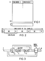
- this shows a coding format applied to a digital television signal.
- Each horizontal line scan of an incoming analog television signal has, as a preliminary, been sampled a predetermined number of times and each of the resulting samples has been pulse code modulation coded into an 8-bit data word.
- the part of the format shown in Figure 1 covers a segment of data which represents 96 or, as shown in Figure 1, 102 successive lines of a television field.
- PAL or more generally a 625-line system
- NTSC or more generally a 525-line system
- the particular sampling system used in this example is a so-called 2:1:1 system applied to a component television signal in which the luminance component signal is sampled at 6.75 MHz and each colour difference component signal is sampled at 3.375 MHz. This results in a total of 720 active samples per horizontal scan line or 13.5 megawords/second.
- the methods and apparatus to be described are generally applicable where the signals are to be transmitted and received, and in particular it will be assumed that the signals are to be recorded on and reproduced from a video tape recorder of the two-head or two-channel type, so that in each channel there are 360 active samples to be recorded for each horizontal scan line. For simplicity, only a single channel will be considered.
- the 360 active samples are split into two sync blocks, each including 180 data words representing samples, and each sync block of 180 data words is split into three data blocks each including sixty data words.
- the segment comprises 96 or 102 lines, and associated with the segment are a further six lines of vertical parity words.
- These vertical parity words are generated by bit-by-bit exclusive-OR (that is, modulo-2) addition of the individual bits of the words in every sixth line of the segment.
- the vertical parity words are generated by a vertical parity word generator as shown in Figure 3, before the synchronizing and check words have been added to the data blocks of data words of the segment.
- the parity word generator comprises an input 1 to which all the words of each of the lines 0 to 95 or 101 of the segment are supplied in sequence (the bits of each individual 8-bit word being supplied in parallel), the input 1 being connected to one input of an exclusive-OR circuit 2 and to one input of a 2:1 selector 3.
- the output of the exclusive-OR circuit 2 is connected to the input of a latch circuit 4, the output of which is connected to the input of a six-line delay (in fact, six lines minus one sample) 5, the output of which is connected to a second input of the exclusive-OR circuit 2 and also to the other input of the 2:1 selector 3.
- the 2:1 selector 3 is controlled to supply to an output 6 either the data, or to supply the generated vertical parity words thereto.
- the latch circuit 4 is cleared so that the contents of the delay 5 are cleared down in preparation for the next segment of data.
- the error detection and correction method to be described in detail below operates by using the check words of each data block to correct random bit errors , random word errors and also possibly short burst errors in the data words and the check words in the segment, and additionally to flag uncorrectable errors.
- the check words of a given data block show that there are, or may be, more error words in the data block than can be corrected by the check words, then all the data words in that data block have an additional bit added thereto, this additional bit being set to say "1" to form an error flag.
- the vertical parity words are used, where possible, to correct the remaining errors. This error correction is possible where only one word of the sixteen or seventeen used to generate each vertical parity word is flagged as being in error.
- interleaving Another previously proposed technique for improving error correction is interleaving, and that technique can also be used in the present error correction formats.
- the effect of interleaving is to spread errors, so that if a burst error occurs there is a greater probability of each of the individual word errors being corrected.
- check words The method of generating the six check words of each data block will now be described.
- a particular feature of these check words is that they are generated not only in dependence on the sixty data words in the data block but also in dependence on each other.
- error correction coding and a known prior error correction code will first be discussed.
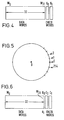
- each of the data words W 0 to W 31 represents in pulse code modulated form a sample level of an analog television signal, the sample range having 256 steps, that is 2 8 .
- Associated with the block are two 8-bit check words K 0 and Kl to provide error correction of one 8-bit data word, by identifying the position of the word in error and the magnitude of the error. This might be considered as providing two simultaneous equations which are solved to find the two unknowns.
- the two check words must each be derived in dependence on all the data words in the block, but in different ways, so as to ensure that they include independent information and hence the equations are soluble.
- a so-called b-adjacent code is one way of obtaining this independence.
- the first check word K 0 is derived by the simple modulo-2 addition of all thirty-two data words. That is: where ⁇ represents modulo-2 addition, achieved by the circuit of Figure 9A.
- the second check word K 1 is derived using a primitive polynomial generator.
- the centre of the circle represents the 8-bit word 00000000.
- steps designated ⁇ 0 , ⁇ 1 , ⁇ 2 , . . ⁇ 254 representing all the different non-zero patterns of an 8-bit code.
- the effect of the polynomial generator which is conveniently formed as an 8-stage feedback shift register interconnected as shown in Figure 9B, is to step an input data word clockwise around the circle when the shift register is clocked once.
- the word may be considered as having been multiplied by bL 0 , that is by one.
- any input 8-bit combination other than 00000000 supplied to the shift register will cycle in a predetermined manner through all the other possible combinations before returning to the original combination.
- the advantages of this modification are that it avoids the need for reverse stepping, so a primitive polynomial generator of the same configuration as used in the coder can be used, and it requires only one delay store, rather than two first-in last-out stores.
- the above-described error correcting code will correct a single error without fail.
- the check words K 0 and K 1 will enable the magnitude and the position of the error to be determined.
- one of the syndromes S 0 or S 1 will be zero and the other will be non-zero, thus indicating that the error is in one of the check words So or S 1 and the data words W 0 to W 31 are error-free.
- the Hamming code will assume a single error and make a wrong correction.
- the check word C 0 is formed as a modulo-2 sum and the check word C 1 is formed using a primitive polynomial generator, but whereas the check words K 0 and K 1 of Figure 4 are both in effect related to the position 31 in the block, the check words C 0 and C 1 are in effect related to the position 33.
- the check words K 0 and K 1 of Figure 4 are derived in dependence on the data words up to and including the last data word W 31 in the position 31
- the check words C o and C 1 of Figure 6 are derived in dependence on the data words up to and including the last data word W 31 in the position 31 plus the check words C 0 and C 1 themselves in the positions 32 and 33.
- each of the check words C 0 and C 1 contains information concerning the other check word, so that in decoding, the check words C o and C l can be treated exactly as if they were data words, and if there is a single error the magnitude and position of the error can be determined even if the error is in one of the check words C 0 or C 1 .
- Equations (1) and (6) show how the check words K 0 and K 1 of Figure 4 could be derived from the data words W 0 to W 31 :
- Equations (11) and (12) can be re-written: and In matrix form this becomes:
- the centre matrix is in fact a Vandemonde determinant, so it always has a real inverse, and equation (15) can be solved for C 0 and C 1 .
- Figure 7 shows in block schematic form a circuit for generating the check words C o and C 1 .
- the incoming data words W 0 to W 31 are supplied by way of an input 10 to first and second primitive polynomial generators 11 and 12 which derive the intermediate words K 0 and K1 respectively, and also to a 2:1 selector 13.
- the intermediate word K 0 derived by the primitive polynomial generator 11 is supplied to a (512 x 8) PROM 14 and the intermediate word K l derived by the primitive polynomial generator 12 is supplied to a (512 x 8) PROM 15.
- the intermediate words K 0 and K 1 are supplied to the input terminals A D to A 7 of the PROMs 14 and 15 respectively and to the input terminals A 8 are supplied switching signals to cause the PROMs 14 and 15 to operate alternately to derive the check words C 0 and C 1 , which are supplied by way of an exclusive - OR circuit 16 to the 2:1 selector 13.
- the output of the 2:1 selector 13 is formed by the data words W 0 to W 31 with the associated check words C 0 and C 1 .
- both the incoming data words and the incoming check words are used, and in consequence the syndromes are derived directly. If there are no errors in the check words then both syndromes are zero. If both the syndromes are non-zero then there is a single error, and the magnitude and position of this error can be found by a Chien search. It may be, of course, that this Chien search reveals that the single error is in one of the check words, in which case the data words are simply passed as valid, with no correction being necessary. If one syndrome is zero and the other is non-zero, then there is more than one error. An improved method of decoding will be described below.
- Figure 8 indicates diagrammatically the sixty data words W o to W 59 (W K-1 ) of a data block, with which are associated the six check words.
- W K-1 the sixty data words
- the use of six check words with sixty data words gives a level of redundancy which has been used in several prior methods, but the number of data words could be different, with appropriate changes to the formats of Figures 1 and 2, so long as the number W K-1 lies within the range 6 to 254 inclusive.
- the data words with the six associated check words form a modified 3-error correcting Reed-Solomon code. It is not required to use the full 3-error correcting capability to correct errors within the data block and the associated check words, and this capability is used merely to correct one or two errors in the data words and the associated check words, the remaining redundancy being exploited for error detection, to implement the vertical parity correction on a segment of data.
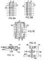
- the check words K 0 to K 5 can be generated from the data words W 0 to W K-1 using primitive polynomial generators as referred to above.
- the particular primitive polynomial generators required to generate the check words KO and K 5 are illustrated in block diagrammatic form in Figures 9A and 9B.
- each of the primitive polynomial generators comprises eight input terminals 20 each connected to one input of a respective exclusive-OR circuit 21, the output of which is connected to the input of a respective shift register stage 22, each having an output connected to a respective output terminal 23.
- Feedback connections as appropriate to generate the required polynomial also extend from the outputs of the shift register stages 22 to respective inputs of the exclusive-OR circuits 21.
- a primitive polynomial generator incorporating a PROM as shown in block form in Figure 10 can be used.
- This primitive polynomial generator comprises input terminals 30 each connected to one input of a respective exclusive-OR circuit 31, the outputs of which are connected to an 8-way D-type flip-flop 32 having eight outputs respectively connected to eight inputs of a PROM 33 having eight outputs respectively connected to eight output terminals 34. Feedback connections also extend from the outputs of the PROM 33 to respective inputs of the exclusive-OR circuits 31.
- the primitive polynomial which is actually generated by this primitive polynomial generator depends on the programming of the PROM 33, and the same basic configuration can therefore be used to form the six primitive polynomial generators required for generating the check words KO to K 5 .
- the check words K O to K 5 would be associated with the data block with no further processing.
- this does not provide effective security against errors in the check words themselves, particularly where there is one error in a check word and one in a data word.
- the check words are modified so that each check word is dependent not only on all the data words but also on all the other check words.
- the first stage check words are generated from the following matrix:
- K 0 to K 5 are the check words which would conventionally be associated with the block. If we now define the check words which are actually to be used as C 0 to C 5 then the check words C and K are related by the following equations:
- the equations (20) must be solved for the check words C 0 to C 5 .
- the equations can be rearranged in determinate form as follows:
- each of the check words K O to K 5 is generated in the conventional manner using related primitive polynomial generators 40 as described above with reference to Figure 10. Only the data words are used in this generation process.
- the output of each primitive polynomial generator 40 addresses a 6-way 8 to 8 code converter in the form of a 2K by 8 PROM 41, the outputs of which are connected to a parity generator 42.
- For each check word one of the 8 to 8 code converter tables is accessed and the check word generated as a modulo-2 sum of all six modified "K" check word values.
- the check words K 0 to K 5 so generated are associated with the data block for transmission or recording.
- the method of decoding at the decoder could be generally as described above in connection with the method using only two check words, but an improved method of decoding will now be described.
- the first operation is to generate six syndromes from the sixty data words and the six check words of each data block.
- the coding structure described above results in the syndromes being available directly the last word, that is the sixth check word, of each data block is available.
- the syndromes are referred to as S 0 , S 1 , S 2 , S 3' S 4 , S 5 .
- the circuitry required can be simplified by modifying the syndromes to avoid reverse stepping. This modification in effect transfers the syndromes from the end of the code. to the beginning, a move of N time slots. Therefore S 0 is multiplied by ⁇ 0 , S 1 is multiplied by ⁇ -N , S 2 is multiplied by ⁇ -2N and so on.
- the new syndromes $ 0 to $ 5 are then:
- the error location algorithm (26) requires a division process. This is best achieved using logarithms, and to avoid the subtraction steps the algorithm (26) can be re-written: In this way simple gating is sufficient to indicate whether during the Chien search an error location has been found.
- the reproduced or received data blocks are supplied by way of a data input 50 to an octal latch circuit 51, the output of which is connected to respective inputs of six primitive polynomial generators 52 and a delay 53.
- Each of the primitive polynomial generators 52 comprises a generator portion 54 shown in more detail in Figure 14 and formed by an exclusive-OR circuit 54A and an octal latch circuit 54B.
- Each of the primitive polynomial generators 52 except the first also comprises a 512 x 8 PROM 55.
- a feedback extends from the output of each PROM 55 to a second input of the respective generator portion 54.
- No PROM 55 is necessary for the first primitive polynomial generator 52, which corresponds to Figure 9A, except in that the exclusive-OR gates and the shift register stages are reversed in position.
- the syndromes generated are modified, and this function also is performed by the PROMs 55.
- control signals are supplied by way of a terminal 56 to the most significant bit terminal of the first three PROMs 55 so that when the primitive polynomial generators 52 have completed generation of the respective syndrome at the receipt of the last word in the data block, the syndrome is then modified and the modified syndrome is supplied to a respective one of six octal latch circuits 57.
- the octal latch circuits 57 therefore respectively hold the modified syndromes 0 , 1 , 2 and 3 and the syndromes S 4 and S 5 for further processing while the next data block is being supplied to the data input 50.
- the expressions P 07 P1 and P 2 of equations (25) are then derived by multipliers 58 and exclusive-OR circuits 59.
- the modified syndrome $ 0 is supplied directly to one input of the first exclusive-OR circuit 59 and the modified syndrome $ 1 is supplied by way of the first multiplier 58 to the other input of the first exclusive-OR circuit 59.
- Each of the multipliers 58 comprises, as shown in more detail in Figure 15, an octal 2:1 selector 58A, an octal latch circuit 58B and three exclusive-OR gates forming an exclusive-OR circuit 58C.
- the input (syndrome) data is passed through the 2:1 selector 58.
- the data is multiplied by $ 1 through the exclusive-OR circuit 58C and held by the octal latch circuit 58B.
- the 2:1 selector 58A selects the output of the octal latch circuit 58B for the remainder of the data block period, and at each clock cycle the data has been multiplied by ⁇ 1 .
- the first multiplier 58 multiplies the modified syndrome $ 1 by ⁇ 1 , and when this operation has been carried out (N-a) times, the output of the first exclusive-OR circuit 59 is P 0 as required by the first of equations (25).
- the second exclusive-OR circuit 59 supplies P1 and the third exclusive-OR circuit 59 supplies P 2 .
- the fourth exclusive-OR circuit 59 supplies a value Q 0 used in finding the error magnitude from ⁇ 2 (N-a)$ 2 0 $ 0 in equation (27).
- the modified syndrome $ 0 is also supplied to an octal latch circuit 60 and to a comparator 61 where it is compared with zero to detect zero errors.
- PROMs 62 which provide look-up tables, having in mind that the outputs of the exclusive-OR circuits 59 represent positions on the ring of Figure 5.
- the outputs of the PROMs 62 are supplied to inputs of octal latch circuits 63, the outputs of the first and third octal latch circuits 63 being supplied to respective inputs of an adder 64 which supplies an output to a 512 x 8 PROM 65.
- the four PROMs 62 respectively convert two values of P 0 , P 1 , P 2 and Q 0 into log form, in particular log (P 0 ), log (Pl2), log (P 2 ) and log (Q 0 ).
- the adder 64 sums log (P 0 ) and log (P 2 ). This gives a 9-bit result which is converted back to an 8-bit code by the PROM 65, the result being held in an octal latch circuit 66.
- Another octal latch circuit 78 holds log (P 1 2 ).
- the outputs of the octal latch circuits 66 and 78 are supplied to a comparator 67 which supplies an output "1" when they are equal, that is:
- An error analysis PROM 68 has three inputs respectively connected to the outputs of the comparators 61 and 67 and of a NAND-gate circuit 79, the input of which is connected to the output of the octal latch circuit 78.
- the three inputs to the PROM 68 are decoded into four outputs, and the output is held in a latch circuit 69 for controlling subsequent stages. These four outputs represent:
- Output (i) representing no error in the data block is supplied to one input address of a 32 x 2 PROM 96.
- Output (ii) representing one error in the data block is latched into a counter 80.
- the counter 80 detects that only one pulse of output (ii) is present in any data block. Should there be zero or more than one single decoded error in the data block then single error correction is inhibited by the PROM 96.
- Output (iii) representing two errors in the data block is latched into a counter 81. Similar to the one error case, two and only two errors must be decoded in each data block. If any other condition is detected, then double error correction is inhibited by the PROM 96.
- Output (iv) is used to control a 2:1 selector 89 which, if an error is detected, switches through the data from an octal latch circuit 88. If no error is detected, then the 2:1 selector 89 supplies zero data.
- error analysis PROM 68 Further inputs to the error analysis PROM 68 can be used to control whether the arrangement decodes single or double errors or neither.
- the error pattern is generated by an adder 70 the output of which represents the log value of equation (29).
- a PROM 71 derives the antilog and the result ( ⁇ y ) is held in an octal latch circuit 72.
- the value of equation (30), ( oc x ) is derived by an exclusive-OR circuit 73 and held in the octal latch circuit 88. If there are no errors, then the data held in the octal latch circuit 72, the modified syndrome 5 0 and the output of the exclusive-OR gate 73 will be zero. If there is one error only, then the data held in the octal latch circuit 72 will be zero and the modified syndrome & will have a magnitude equal to the error. Hence the error pattern will be available on the output of the exclusive-OR gate 73.
- the error pattern held in the octal latch circuit 88 is supplied to the 2:1 selector 89. If one or two error positions are decoded, then the error pattern is passed through to an octal latch circuit 90 and to an error pattern
- the output of the octal latch circuit 90 is passed to a delay 76 for storage, and to syndrome generators 74 and 75.
- the syndrome generators 74 and 75 generate, in the same manner as the primitive polynomial generators 52, the values of two syndromes S' 4 and S' S and at the end of the data block these values are held in octal latch circuits 82 and 83. If the error pattern is valid, then the syndromes S' 4 and S' 5 will be equal to S 4 and S 5 respectively. This condition is detected by comparators 86 and 87 respectively. The output from the comparator 86 is used to enable the comparator 87, and hence the output of the comparator 87 represents the equality of both syndrome pairs. This output is used to control the PROM 96.
- the error pattern from the 2:1 selector 89 is also supplied to the error pattern detector PROM 91 together with a word/bit control.
- the PROM 91 decodes every data pattern as valid via a valid two-error detector 92 and a 1 K x 1 PROM 94. If the control is in the bit state, then the input to the valid two-error detector 92 is valid only if a single bit error is decoded in the error word. Also, the input to a valid burst error detector 93 is valid if only two sequential error words are representative of a 9-bit or less error pattern. The results of these tests are supplied to the PROM 94 which decodes the valid error patterns and supplies a control signal via a latch circuit 95 to the PROM 96.
- the inputs to the PROM 96 enable zero, single and two-error patterns to be decoded and enable, via a latch circuit 97, the output of an octal latch circuit 98 to correct the errors in the data via an exclusive-OR gate 77 to which the data is also supplied from the delay 53.
- a second output from the PROM 96 via the latch circuit 97 is used to supply a signal to an output 84 to indicate that an uncorrectable error pattern has been found, and this is then used for decoding using the vertical parity check words.
- the 2:1 selector 89 will select the all "0" signal. If there is a single error, then the PROM 71 will effectively be disabled and the output of the exclusive-OR circuit 73 will be the modified syndrome 1 5 0 . If, however, there are two errors the PROM 71 will be operative and the magnitudes of the errors will be found as described above. In all cases, therefore, the output of the 2:1 selector 89 will be the error pattern, although in cases where there are no errors, the error pattern will be all "0".
- the error pattern is supplied to the delay 76 and thence to one input of the exclusive-OR circuit 77 to be modulo-2 added to the data which is supplied to the other input of the exclusive-OR circuit 77 from the delay 53. In this way the errors in the data are corrected and the corrected data is supplied to an output 85.
- the error pattern from the 2:1 selector 89 is supplied to the syndrome generators 74 and 75.
- the check is effected making use of the latter part of equation (26).
- the fifth and sixth primitive polynomial generators 52 generate the syndromes S 4 and S 5 and they are supplied by way of the fifth and sixth latch circuits 57 and the octal latch circuits 85 and 95 to the comparators 86 and 87. A simple comparison in each of the comparators 86 and 87 is all that is necessary.
- the syndromes S4 and S supplied to the comparators 86 and 87 respectively from the fifth primitive polynomial generator 52 and the syndrome generator 74, and from the sixth polynomial generator 52 and the syndrome generator 75 will be the same, and an "error valid" signal will be supplied from the comparator 87 to the PROM 96.
- the error-corrected data can be allowed through, it being accepted that the error correction will have failed if there are more than about five errors in the block. This may give a failure rate of about 1 in 10 6 and this may well not be acceptable. To improve the failure rate to about 1 in 10 9 some additional protection is provided, as will now be described.
- the error pattern detector PROM 91 is an 8-to-7 code converter, the top bit indicating the presence of a non-zero input pattern, the next three bits of the output indicating in binary coded decimal the distance of the first error bit from the end of the first word and the bottom three bits of the output indicating in binary coded decimal the distance of the second error bit from the beginning of the second word.
- These binary coded decimal values are supplied by the latch circuit 95 to the PROM 96. Only therefore if one of the criteria mentioned above is satisfied will the delay 76 be enabled to use the error patterns which have been derived to correct the data, by supplying them to the exclusive-OR circuit 77.
- the vertical parity words for the parity check blocks to be associated with the data blocks of each segment are generated by a vertical parity word generator generally as shown in Figure 3.
- the delay 5 has a delay time of six horizontal scan lines minus one sample.
- the input supplied to the input 1 comprises the data words, and, with the appropriate timing, all "0" words for the parity positions.
- Six lines of vertical parity words are generated for each segment comprising parts of 96 or 102 horizontal scan lines.
- the data words and the vertical parity words are supplied segment by segment to the input 100 of the vertical parity check arrangement which forms another part of the decoder and which is shown in block form in Figure 16.
- the input 100 is connected to one input of an exclusive-OR circuit 101 and to the input of an segment delay 102.
- the output of the exclusive-OR circuit 101 is connected by way of a latch circuit 103 to the input of a six lines minus one sample delay 104, the output of which is connected back to a second input of the exclusive-OR circuit 101.
- the output of the delay 104 is also connected by way of a latch circuit 105 to one input of an exclusive-OR 106.
- the output of the segment delay 102 is connected to the other input of the exclusive-OR circuit 106.
- Data invalid flags such as signals generated in the apparatus of Figure 13, and indicating uncorrected errors, are supplied by way of another input 107 to an input of a PROM 108.
- the output of the PROM 108 is connected by way of a latch circuit 109 to a six line delay 110, the output of which is connected back to the data input of the PROM 108.
- the PROM 108 also has an output for supplying a clear signal to the latch circuit 105.
- the syndromes are generated by the loop comprising the exclusive-OR circuit 101, the latch circuit 103 and the delay 104.
- the delay 104 supplies the syndrome pattern to the latch circuit 105.
- the PROM 108 has generated a 2-bit code which identifies for each data block syndrome whether there are zero, one or more than one errors in the segment corresponding to that syndrome data block. Correction is effected by the exclusive-OR circuit 106 which modulo-2 sums the data delayed by the delay 102 with the syndrome held in the latch circuit 105. However, this only occurs when the PROM 108 indicates that there is only a single error pattern.
- the PROM 108 clears the latch circuit 105 so that an all "zero" pattern is modulo-2 summed with the data by the exclusive-OR circuit 108.
- the exclusive-OR circuit then supplies the resulting data to an output 111. In general, if at this stage some of the data is still flagged as being in error, because the errors therein cannot be detected or cannot be corrected by the method described above, then the errors will be concealed.
Landscapes
- Engineering & Computer Science (AREA)
- Physics & Mathematics (AREA)
- Signal Processing (AREA)
- Algebra (AREA)
- General Physics & Mathematics (AREA)
- Mathematical Physics (AREA)
- Pure & Applied Mathematics (AREA)
- Probability & Statistics with Applications (AREA)
- Theoretical Computer Science (AREA)
- Multimedia (AREA)
- Error Detection And Correction (AREA)
- Detection And Correction Of Errors (AREA)
Applications Claiming Priority (2)
| Application Number | Priority Date | Filing Date | Title |
|---|---|---|---|
| GB08235962A GB2132393B (en) | 1982-12-17 | 1982-12-17 | Methods and apparatus for correcting errors in binary data |
| GB8235962 | 1982-12-17 |
Publications (2)
| Publication Number | Publication Date |
|---|---|
| EP0112676A2 true EP0112676A2 (fr) | 1984-07-04 |
| EP0112676A3 EP0112676A3 (fr) | 1986-12-30 |
Family
ID=10535044
Family Applications (1)
| Application Number | Title | Priority Date | Filing Date |
|---|---|---|---|
| EP83307515A Withdrawn EP0112676A3 (fr) | 1982-12-17 | 1983-12-09 | Méthode et dispositif pour corriger des erreurs dans des données numériques |
Country Status (5)
| Country | Link |
|---|---|
| US (1) | US4586183A (fr) |
| EP (1) | EP0112676A3 (fr) |
| JP (1) | JPH0612592B2 (fr) |
| CA (1) | CA1214562A (fr) |
| GB (1) | GB2132393B (fr) |
Cited By (6)
| Publication number | Priority date | Publication date | Assignee | Title |
|---|---|---|---|---|
| GB2149540A (en) * | 1983-11-10 | 1985-06-12 | Gen Signal Corp | Vital processor |
| EP0189811A1 (fr) * | 1985-01-21 | 1986-08-06 | Matsushita Electric Industrial Co., Ltd. | Appareil pour enregistrer et reproduire des informations optiques |
| EP0191410A2 (fr) * | 1985-02-08 | 1986-08-20 | Hitachi, Ltd. | Méthode pour la transmission de données numériques |
| EP0201330A2 (fr) * | 1985-05-08 | 1986-11-12 | Thinking Machines Corporation | Appareil pour mettre en mémoire des mots de données digitales |
| EP0431576A2 (fr) * | 1989-12-08 | 1991-06-12 | Matsushita Electric Industrial Co., Ltd. | Décodeur d'un code BCH et méthode pour le décodage d'un code BCH |
| US5202979A (en) * | 1985-05-08 | 1993-04-13 | Thinking Machines Corporation | Storage system using multiple independently mechanically-driven storage units |
Families Citing this family (13)
| Publication number | Priority date | Publication date | Assignee | Title |
|---|---|---|---|---|
| JPS60186942A (ja) * | 1984-02-24 | 1985-09-24 | Victor Co Of Japan Ltd | デイジタル乗算回路 |
| JPH0619913B2 (ja) * | 1984-03-30 | 1994-03-16 | パイオニア株式会社 | ビデオフオ−マツト信号に担持されるデ−タのエラ−訂正方式 |
| JPS61285827A (ja) * | 1985-06-12 | 1986-12-16 | Hitachi Ltd | 誤り制御装置 |
| GB8631027D0 (en) * | 1986-12-30 | 1987-02-04 | Questech Ltd | Recording editing & moving television pictures |
| JPH03198544A (ja) * | 1989-12-27 | 1991-08-29 | Nec Corp | パリティ計数回路 |
| US5115436A (en) * | 1990-05-04 | 1992-05-19 | Bell Communications Research | Forward error correction code system |
| US5224106A (en) * | 1990-05-09 | 1993-06-29 | Digital Equipment Corporation | Multi-level error correction system |
| WO1994010798A1 (fr) * | 1992-11-05 | 1994-05-11 | Ampex Systems Corporation | Circuit de detection et de correction d'erreurs de signaux de synchronisation video |
| US5398143A (en) * | 1992-12-01 | 1995-03-14 | Samsung Electronics Co., Ltd. | Data placement on tape for a digital video tape recorder suitable for high speed picture playback |
| FR2740925A1 (fr) * | 1995-11-08 | 1997-05-09 | Canon Kk | Procede et dispositif de detection et de correction d'une eventuelle erreur dans une suite de nombres |
| US6041430A (en) * | 1997-11-03 | 2000-03-21 | Sun Microsystems, Inc. | Error detection and correction code for data and check code fields |
| US6920600B2 (en) * | 2002-01-23 | 2005-07-19 | Thomson Licensing S.A. | Dual chien search blocks in an error-correcting decoder |
| JP4299257B2 (ja) * | 2005-03-09 | 2009-07-22 | 株式会社理研オプテック | 荷重計のゼロ点補正回路 |
Citations (4)
| Publication number | Priority date | Publication date | Assignee | Title |
|---|---|---|---|---|
| US4142174A (en) * | 1977-08-15 | 1979-02-27 | International Business Machines Corporation | High speed decoding of Reed-Solomon codes |
| US4238852A (en) * | 1978-04-17 | 1980-12-09 | Sony Corporation | Error correcting system |
| EP0061288A2 (fr) * | 1981-03-23 | 1982-09-29 | Sony Corporation | Traitement de signaux de télévision numériques |
| EP0102533A2 (fr) * | 1982-09-02 | 1984-03-14 | Discovision Associates | Mémoire de données numériques dans un format vidéo |
Family Cites Families (7)
| Publication number | Priority date | Publication date | Assignee | Title |
|---|---|---|---|---|
| NL130511C (fr) * | 1963-10-15 | |||
| JPS5857781B2 (ja) * | 1978-01-17 | 1983-12-21 | 三菱電機株式会社 | 符号化復号化方式 |
| US4151510A (en) * | 1978-04-27 | 1979-04-24 | Honeywell Information Systems | Method and apparatus for an efficient error detection and correction system |
| JPS55115753A (en) * | 1979-02-27 | 1980-09-05 | Sony Corp | Pcm signal transmission method |
| JPS55131860A (en) * | 1979-03-30 | 1980-10-14 | Matsushita Electric Ind Co Ltd | Error correction unit |
| JPS574629A (en) * | 1980-05-21 | 1982-01-11 | Sony Corp | Data transmitting method capable of correction of error |
| US4413339A (en) * | 1981-06-24 | 1983-11-01 | Digital Equipment Corporation | Multiple error detecting and correcting system employing Reed-Solomon codes |
-
1982
- 1982-12-17 GB GB08235962A patent/GB2132393B/en not_active Expired
-
1983
- 1983-12-06 CA CA000442633A patent/CA1214562A/fr not_active Expired
- 1983-12-09 EP EP83307515A patent/EP0112676A3/fr not_active Withdrawn
- 1983-12-15 US US06/561,782 patent/US4586183A/en not_active Expired - Lifetime
- 1983-12-16 JP JP58238691A patent/JPH0612592B2/ja not_active Expired - Lifetime
Patent Citations (4)
| Publication number | Priority date | Publication date | Assignee | Title |
|---|---|---|---|---|
| US4142174A (en) * | 1977-08-15 | 1979-02-27 | International Business Machines Corporation | High speed decoding of Reed-Solomon codes |
| US4238852A (en) * | 1978-04-17 | 1980-12-09 | Sony Corporation | Error correcting system |
| EP0061288A2 (fr) * | 1981-03-23 | 1982-09-29 | Sony Corporation | Traitement de signaux de télévision numériques |
| EP0102533A2 (fr) * | 1982-09-02 | 1984-03-14 | Discovision Associates | Mémoire de données numériques dans un format vidéo |
Non-Patent Citations (2)
| Title |
|---|
| FTCS, 12TH ANNUAL INTERNATIONAL SYMPOSIUM, FAULT-TOLERANT COMPUTING, Santa Monica, California, US, 22nd-24th June 1982, pages 317-320, IEEE, New York, US; H. DONG: "Modified Berger codes for detection of unidirectional errors" * |
| IBM TECHNICAL DISCLOSURE BULLETIN, vol. 15, no. 4, September 1972, pages 1128-1130, New York, US; N.F. BRICKMAN et al.: "Error-correction system for high-data rate systems" * |
Cited By (12)
| Publication number | Priority date | Publication date | Assignee | Title |
|---|---|---|---|---|
| GB2149540A (en) * | 1983-11-10 | 1985-06-12 | Gen Signal Corp | Vital processor |
| GB2169114A (en) * | 1983-11-10 | 1986-07-02 | Gen Signal Corp | Vital processor v |
| US4831521A (en) * | 1983-11-10 | 1989-05-16 | General Signal Corporation | Vital processor implemented with non-vital hardware |
| EP0189811A1 (fr) * | 1985-01-21 | 1986-08-06 | Matsushita Electric Industrial Co., Ltd. | Appareil pour enregistrer et reproduire des informations optiques |
| EP0191410A2 (fr) * | 1985-02-08 | 1986-08-20 | Hitachi, Ltd. | Méthode pour la transmission de données numériques |
| EP0191410A3 (en) * | 1985-02-08 | 1988-08-24 | Hitachi, Ltd. | Method of transmitting digital data |
| EP0201330A2 (fr) * | 1985-05-08 | 1986-11-12 | Thinking Machines Corporation | Appareil pour mettre en mémoire des mots de données digitales |
| EP0201330A3 (en) * | 1985-05-08 | 1988-03-02 | Thinking Machines Corporation | Apparatus for storing digital data words |
| US5202979A (en) * | 1985-05-08 | 1993-04-13 | Thinking Machines Corporation | Storage system using multiple independently mechanically-driven storage units |
| EP0431576A2 (fr) * | 1989-12-08 | 1991-06-12 | Matsushita Electric Industrial Co., Ltd. | Décodeur d'un code BCH et méthode pour le décodage d'un code BCH |
| EP0431576A3 (en) * | 1989-12-08 | 1992-04-29 | Matsushita Electric Industrial Co., Ltd. | Bch code decoder and method for decoding a bch code |
| US5216676A (en) * | 1989-12-08 | 1993-06-01 | Matsushita Electric Industrial Co., Ltd. | Bch code decoder and method for decoding a bch code |
Also Published As
| Publication number | Publication date |
|---|---|
| GB2132393A (en) | 1984-07-04 |
| EP0112676A3 (fr) | 1986-12-30 |
| GB2132393B (en) | 1986-05-14 |
| US4586183A (en) | 1986-04-29 |
| JPS59135605A (ja) | 1984-08-03 |
| JPH0612592B2 (ja) | 1994-02-16 |
| CA1214562A (fr) | 1986-11-25 |
Similar Documents
| Publication | Publication Date | Title |
|---|---|---|
| US4607367A (en) | Correcting errors in binary data | |
| US4586183A (en) | Correcting errors in binary data | |
| US4497058A (en) | Method of error correction | |
| EP0170328B1 (fr) | Appareil pour corriger et masquer des erreurs dans une suite de données et dispositif de reproduction vidéo et/ou audio comprenant un tel appareil | |
| US4546474A (en) | Method of error correction | |
| CA1201810A (fr) | Methode de correction d'erreur pour le transfert de blocs de bits d'information, dispositif pour appliquer cette methode, decodeur utilise avec cette methode et dispositif comprenant ce decodeur | |
| EP0072640B1 (fr) | Méthodes pour la correction d'erreurs de données | |
| US4491943A (en) | Method for transmitting time-sharing multidata | |
| EP0061288B1 (fr) | Traitement de signaux de télévision numériques | |
| US4541091A (en) | Code error detection and correction method and apparatus | |
| KR880000426B1 (ko) | 이중 부호화 리드 솔로몬 코드에 대한 복호화 방법 및 장치 | |
| US4569051A (en) | Methods of correcting errors in binary data | |
| US4117458A (en) | High speed double error correction plus triple error detection system | |
| US4567518A (en) | System for decoding and displaying encoded television pictures | |
| EP0278383A2 (fr) | Méthode de correction d'erreur utilisant des codes reed-solomon | |
| US3873971A (en) | Random error correcting system | |
| EP0334580B1 (fr) | Système et méthode pour la réalisation de correction d'erreurs de signaux audio, sur bande à format de trame fixe vidéo | |
| US4217660A (en) | Method and apparatus for the coding and decoding of digital data | |
| US3544963A (en) | Random and burst error-correcting arrangement | |
| JPS632370B2 (fr) | ||
| US4521886A (en) | Quasi-soft decision decoder for convolutional self-orthogonal codes | |
| US5544179A (en) | Mis-synchronization detection system using a combined error correcting and cycle identifier code | |
| JPH048974B2 (fr) | ||
| JP2684031B2 (ja) | データの復号化方法 | |
| KR920000396B1 (ko) | 에러정정방법(error訂正方法) |
Legal Events
| Date | Code | Title | Description |
|---|---|---|---|
| PUAI | Public reference made under article 153(3) epc to a published international application that has entered the european phase |
Free format text: ORIGINAL CODE: 0009012 |
|
| AK | Designated contracting states |
Designated state(s): AT DE FR GB NL |
|
| PUAL | Search report despatched |
Free format text: ORIGINAL CODE: 0009013 |
|
| AK | Designated contracting states |
Kind code of ref document: A3 Designated state(s): AT DE FR GB NL |
|
| 17P | Request for examination filed |
Effective date: 19870514 |
|
| 17Q | First examination report despatched |
Effective date: 19880721 |
|
| STAA | Information on the status of an ep patent application or granted ep patent |
Free format text: STATUS: THE APPLICATION HAS BEEN WITHDRAWN |
|
| 18W | Application withdrawn |
Withdrawal date: 19891015 |
|
| R18W | Application withdrawn (corrected) |
Effective date: 19891015 |
|
| RIN1 | Information on inventor provided before grant (corrected) |
Inventor name: WILKINSON, JAMES HEDLEY |