EP0112265B1 - Automatic fast lowering device for a pantograph - Google Patents
Automatic fast lowering device for a pantograph Download PDFInfo
- Publication number
- EP0112265B1 EP0112265B1 EP83440058A EP83440058A EP0112265B1 EP 0112265 B1 EP0112265 B1 EP 0112265B1 EP 83440058 A EP83440058 A EP 83440058A EP 83440058 A EP83440058 A EP 83440058A EP 0112265 B1 EP0112265 B1 EP 0112265B1
- Authority
- EP
- European Patent Office
- Prior art keywords
- pantograph
- lowering device
- rapid lowering
- contacts
- lifting spring
- Prior art date
- Legal status (The legal status is an assumption and is not a legal conclusion. Google has not performed a legal analysis and makes no representation as to the accuracy of the status listed.)
- Expired
Links
Images


Classifications
-
- B—PERFORMING OPERATIONS; TRANSPORTING
- B60—VEHICLES IN GENERAL
- B60L—PROPULSION OF ELECTRICALLY-PROPELLED VEHICLES; SUPPLYING ELECTRIC POWER FOR AUXILIARY EQUIPMENT OF ELECTRICALLY-PROPELLED VEHICLES; ELECTRODYNAMIC BRAKE SYSTEMS FOR VEHICLES IN GENERAL; MAGNETIC SUSPENSION OR LEVITATION FOR VEHICLES; MONITORING OPERATING VARIABLES OF ELECTRICALLY-PROPELLED VEHICLES; ELECTRIC SAFETY DEVICES FOR ELECTRICALLY-PROPELLED VEHICLES
- B60L5/00—Current collectors for power supply lines of electrically-propelled vehicles
- B60L5/18—Current collectors for power supply lines of electrically-propelled vehicles using bow-type collectors in contact with trolley wire
- B60L5/22—Supporting means for the contact bow
- B60L5/28—Devices for lifting and resetting the collector
-
- B—PERFORMING OPERATIONS; TRANSPORTING
- B60—VEHICLES IN GENERAL
- B60L—PROPULSION OF ELECTRICALLY-PROPELLED VEHICLES; SUPPLYING ELECTRIC POWER FOR AUXILIARY EQUIPMENT OF ELECTRICALLY-PROPELLED VEHICLES; ELECTRODYNAMIC BRAKE SYSTEMS FOR VEHICLES IN GENERAL; MAGNETIC SUSPENSION OR LEVITATION FOR VEHICLES; MONITORING OPERATING VARIABLES OF ELECTRICALLY-PROPELLED VEHICLES; ELECTRIC SAFETY DEVICES FOR ELECTRICALLY-PROPELLED VEHICLES
- B60L2200/00—Type of vehicles
- B60L2200/26—Rail vehicles
Definitions
- the rapid descent of the pantograph can only occur when the catenary is energized, which avoids any risk of unexpected triggering, in particular in the case of repairs carried out on the pantograph.
- the contact system comprises at least a first isolated contact secured to the bow and at least one second isolated contact secured to the set of articulated frames, one of these contacts being electrically connected to the catenary, while the other is connected to an electrical tripping device capable of releasing one of the ends of the mounting spring, this first and this second contact being arranged so as to cooperate together when the bow is subjected to a frontal overload, in order to power the trip device.
- a group of first contacts and a group of second contacts are provided, arranged so as to cooperate in one or the other of the two directions of travel of the vehicle.
- pantograph is protected, not only in the event of a frontal overload; but also in the event of a side impact or a simple overflow of the catenary. Indeed, the catenary then strikes the third contact, which causes the supply of the electrical trip device and therefore the rapid descent of the pantograph.
- said end of the rising spring is extended by a rod provided with a stop limiting the relaxation of the spring when it is released by the electric triggering device, which makes it possible to reduce. the effect of the pantograph impact on the roof of the vehicle during its rapid descent movement.
- the stop is able to receive a gripping element for retensioning the mounting spring.
- the pantograph is conventionally equipped with two rising springs 5 and 6 ensuring its deployment. These springs are fixed at one end to the chassis 2 and at the other end on a lug 7 secured to the main shaft 8 of the set of articulated frames 1.
- the bow 3 is fixed to the assembly 1 by means of an elastic suspension which here consists essentially of two spring pots such as 11, in which the bow is supported by flanges such as 12.
- the pantograph is also equipped with a so-called rapid descent device for automatically triggering the fall of the pantograph when the bow is subjected to a abnormal constraint.
- This device essentially consists of an electrical contact system housed in the head of the pantograph and forming at least one switch which, when it closes, causes the relaxation of one of the rising springs, in this case the spring. 5, by means which will be described in more detail below.
- the contact system comprises first of all two first contacts 13, 14, integral with the bow 3.
- These contacts consist of sections of metal tube which are fixed at a certain distance from each other and in an adjustable manner on the flange 12 supporting the bow, by means of appropriate collars 15.
- a rod 16 is moreover fixed in isolation to the spring pot 11 by means of a bracket 17.
- This rod is stripped at its ends and thus constitutes second contacts 18, 19 which are designed to cooperate with the first contacts 13, 14 by forming two normally open switches, respectively 13-18 and 14-19.
- the pantograph may possibly be equipped on the other side with a similar contact system, arranged between the second spring pot 11 and the corresponding flange 12.
- the first contacts 13, 14 are electrically connected to the parts of the bow intended to rub against the catenary 4, either by cables, or directly by means of the flange 12.
- the second contacts 18, 19 they are electrically connected by a cable 20 to an electrical trip device 21, visible in FIGS. 6 to 9 and which is capable of causing the release of the ascent spring 5.
- the contact system according to the invention is completed by a third contact such as 22, located in the vicinity of the end of the horns 23 of the bow 3.
- This contact consists here of a stud which is fixed in isolation on a bar 24 transversely connecting the two elements of the bow, at the end of the horns 23.
- Such contact is provided on either side of the bow and they are both connected to the electrical tripping device 21 by cable 25.
- the end of the rise spring 5 which is not connected to a lug 7, is constituted by a sphere 26 designed to engage in a fork 27 movably mounted around an axis 28 supported by the chassis 2.
- the fork 27 is normally locked in the spring retaining position 5 by the triggering device 21 which here consists of an electromagnet capable of causing the erasure of a stud 29 engaging in a socket 30 integral with the fork.
- the triggering device 21 which here consists of an electromagnet capable of causing the erasure of a stud 29 engaging in a socket 30 integral with the fork.
- the stud 29 and the bush 30 will advantageously be made of stainless steel.
- the end 26 of the spring 5 is further extended by a rod 31 provided at its end with a stop 32 designed to cooperate with a shoulder 33 formed for this purpose on the chassis 2.
- the stop 32 is further provided with a thread 34, the purpose of which will appear more clearly later.
- the pantograph Under the effect of the relaxation of the spring 5, the pantograph immediately descends by its own weight, but its fall on the roof of the carrier vehicle is nevertheless damped, on the one hand because only part of the stroke of the spring is released due to the presence of the stop 32, and secondly because the action of the second rise spring 6 remains entirely.
- the impact can be reduced to a minimum, so as not to risk damaging the pantograph or the roof of the vehicle.
- the device according to the invention works equally well in the two directions of travel of the vehicle.
- FIG. 5 it can be seen for example that if the pantograph is subjected to a frontal impact while the vehicle is moving in the other direction, it is the switch formed by the contacts 13 and 18 which will intervene to cause the 'supply of the electromagnet 21 and therefore the rapid descent of the pantograph under the same conditions as above.
- pantograph equipped in accordance with the invention is therefore protected both against frontal impacts and lateral impacts, and also in the case of a simple lateral overflow of the catenary.
- the rapid descent device can only be triggered when the latter is energized, which avoids any risk of unexpected triggering, in particular when repairs are made to the pantograph. It goes without saying, moreover, that the electromagnet 21 could easily be replaced by another device performing the same function, for example a pyrotechnic device, provided that it is electrically tripped.
- the pantograph can easily be put back into service by proceeding in the manner illustrated in FIGS. 8 and 9.
Abstract
Description
La présente invention concerne un dispositif pour provoquer automatiquement la descente rapide d'un pantographe constitué par un ensemble de cadres articulés fixé sur le toit d'un véhicule à traction électrique et supportant par l'intermédiaire d'une suspension élastique un archet destiné à venir en contact par frottement sur la caténaire, avec au moins un ressort de montée assurant le déploiement du pantographe et un organe de commande pour assurer son repliement à plat sur le toit du véhicule lorsque le pantographe se trouve soumis à une contrainte anormale, en provoquant la détente du ressort de montée.The present invention relates to a device for automatically causing the rapid descent of a pantograph consisting of a set of articulated frames fixed on the roof of an electric traction vehicle and supporting by means of an elastic suspension a bow intended to come in frictional contact on the catenary, with at least one rising spring ensuring the deployment of the pantograph and a control member to ensure its folding flat on the roof of the vehicle when the pantograph is subjected to abnormal stress, causing the rebound of the rising spring.
On connaît déjà divers dispositifs de ce genre permettant notamment, en cas de surcharge. sur le pantographe, d'assurer sa descente rapide en vue d'éviter qu'il ne soit endommagé ou qu'il n'endommage lui-même la caténaire et ses éléments de suspension.Various devices of this type are already known, making it possible in particular in the event of overload. on the pantograph, to ensure its rapid descent in order to prevent it from being damaged or damaging the catenary and its suspension elements itself.
Dans l'un de ces dispositifs connus par exemple, lors d'une surcharge mécanique sur les cadres articulés du pantographe, on provoque une détente du ressort de montée et par conséquent la descente du pantographe sous l'action de son propre poids, grâce au dépassement d'un certain seuil d'effort d'un limiteur d'effort (EP-A1-42334) ou grâce au cisaillement d'un boulon de rupture spécialement prévu à cet effet.In one of these known devices, for example, during a mechanical overload on the articulated frames of the pantograph, the rebound spring is triggered and therefore the pantograph is lowered under the action of its own weight, thanks to the exceeding a certain force threshold of a force limiter (EP-A1-42334) or by shearing a break bolt specially provided for this purpose.
Tous ces dispositifs présentent cependant un certain nombre d'inconvénients parmi lesquels on peut citer en particulier le fait qu'ils peuvent se déclencher inopinément, par exemple lors de réparations effectuées sur le pantographe, et provoquer ainsi des incidents corporels.However, all of these devices have a certain number of drawbacks, among which we can cite in particular the fact that they can be triggered unexpectedly, for example during repairs carried out on the pantograph, and thus cause bodily incidents.
La présente invention a donc pour but principal de remédier à cet inconvénient et, pour ce faire, elle a pour objet un dispositif de descente rapide qui. se caractérise essentiellement en ce qu'il comprend un système de contacts électriques alimenté à partir de la caténaire et formant au moins un interrupteur qui se ferme sous l'effet d'une contrainte anormale, pour alimenter un dispositif de déclenchement du ressort de montée.The main object of the present invention is therefore to remedy this drawback and, to do this, it relates to a rapid descent device which. is essentially characterized in that it comprises an electrical contact system supplied from the catenary and forming at least one switch which closes under the effect of an abnormal constraint, to supply a device for triggering the rising spring.
Ainsi, la descente rapide du pantographe ne peut se produire que lorsque la caténaire est sous tension, ce qui évite tout risque de déclenchement inopiné, notamment dans le cas de réparations effectuées sur le pantographe.Thus, the rapid descent of the pantograph can only occur when the catenary is energized, which avoids any risk of unexpected triggering, in particular in the case of repairs carried out on the pantograph.
De préférence, le système de contacts comprend au moins un premier contact isolé solidaire de l'archet et au moins un deuxième contact isolé solidaire de l'ensemble de cadres articulés, l'un de ces contacts étant relié électriquement à la caténaire, tandis que l'autre est relié à un dispositif de déclenchement électrique apte à libérer l'une des extrémités du ressort de montée, ce premier et ce deuxième contacts étant disposés de manière à coopérer ensemble lorsque l'archet est soumis à une surcharge frontale, afin de provoquer l'alimentation du dispositif de déclenchement.Preferably, the contact system comprises at least a first isolated contact secured to the bow and at least one second isolated contact secured to the set of articulated frames, one of these contacts being electrically connected to the catenary, while the other is connected to an electrical tripping device capable of releasing one of the ends of the mounting spring, this first and this second contact being arranged so as to cooperate together when the bow is subjected to a frontal overload, in order to power the trip device.
Grâce à cette disposition, la descente rapide du pantographe se trouve déclenchée par un déplacement déterminé de l'archet par rapport à l'ensemble de cadres articulés, à l'encontre de l'action exercée par la suspension élastique, ce qui permet d'obtenir une beaucoup plus grande sensibilité dans le déclenchement. De plus, la force de déclenchement nécessaire peut être réglée facilement en modifiant la position relative des contacts.Thanks to this arrangement, the rapid descent of the pantograph is triggered by a determined displacement of the bow relative to the set of articulated frames, against the action exerted by the elastic suspension, which allows achieve much greater sensitivity in triggering. In addition, the required release force can be easily adjusted by changing the relative position of the contacts.
De préférence également, on prévoit un groupe de premiers contacts et un groupe de deuxièmes contacts, disposés de manière à coopérer dans l'un ou l'autre des deux sens de marche du véhicule.Preferably also, a group of first contacts and a group of second contacts are provided, arranged so as to cooperate in one or the other of the two directions of travel of the vehicle.
Par ailleurs, le système de contacts comprend en outre avantageusement un troisième contact isolé et électriquement relié au dispositif de déclenchement électrique et qui est disposé au voisinage de chacune des extrémités latérales de l'archet, de manière à être heurté directement par la caténaire lors d'un débordement latéral de celle-ci.Furthermore, the contact system advantageously further comprises a third insulated contact electrically connected to the electrical tripping device and which is arranged in the vicinity of each of the lateral ends of the bow, so as to be struck directly by the catenary during 'a lateral overflow thereof.
Ainsi, le pantographe se trouve protégé, non seulement en cas de surcharge frontale ; mais également en cas de choc latéral ou de simple débordement de la caténaire. En effet, la caténaire vient alors heurter le troisième contact, ce qui provoque l'alimentation du dispositif de déclenchement électrique et par conséquent la descente rapide du pantographe.Thus, the pantograph is protected, not only in the event of a frontal overload; but also in the event of a side impact or a simple overflow of the catenary. Indeed, the catenary then strikes the third contact, which causes the supply of the electrical trip device and therefore the rapid descent of the pantograph.
Dans une forme de réalisation particulière de l'invention, le dispositif de déclenchement électrique est conçu pour coopérer avec une fourchette mobile dans laquelle vient s'engager ladite extrémité du ressort de montée.In a particular embodiment of the invention, the electrical trip device is designed to cooperate with a movable fork in which engages said end of the rise spring.
Ce dispositif de déclenchement électrique pourra par exemple être constitué par un électro-aimant apte à provoquer l'effacement d'un goujon de blocage de la fourchette dans sa position de retenue du ressort de montée.This electrical tripping device may for example be constituted by an electromagnet capable of causing the erasure of a locking pin of the fork in its position for retaining the rising spring.
De préférence, ladite extrémité du ressort de montée est prolongée par une tige pourvue d'une butée limitant la détente du ressort lors de sa libération par le dispositif de déclenchement électrique, ce qui permet de réduire. l'effet du choc du pantographe sur le toit du véhicule lors de son mouvement de descente rapide.Preferably, said end of the rising spring is extended by a rod provided with a stop limiting the relaxation of the spring when it is released by the electric triggering device, which makes it possible to reduce. the effect of the pantograph impact on the roof of the vehicle during its rapid descent movement.
De plus, la butée est apte à recevoir un élément de prise permettant de retendre le ressort de montée.In addition, the stop is able to receive a gripping element for retensioning the mounting spring.
En effet, grâce à la butée, le ressort ne tombe pas sur le toit du véhicule et reste guidé dans sa suspension, ce qui permet ensuite de le retendre très facilement au moyen par exemple d'un élément fileté venant en prise dans ladite butée, et ce quelle que soit la position en hauteur du pantographe.In fact, thanks to the stop, the spring does not fall on the roof of the vehicle and remains guided in its suspension, which then makes it possible to tension it very easily by means, for example, of a threaded element engaging in said stop, regardless of the height position of the pantograph.
Par ailleurs, lorsque le pantographe est équipé de deux ressorts de montée, comme c'est souvent le cas, un seul de ces ressorts est associé à un dispositif de déclenchement électrique, afin de réduire encore l'effet du choc du pantographe sur le toit du véhicule porteur.Furthermore, when the pantograph is equipped with two rising springs, as is often the case, only one of these springs is associated with a electrical release device, in order to further reduce the impact of the pantograph shock on the roof of the carrier vehicle.
Une forme d'exécution de l'invention est décrite ci-après à titre d'exemple, en référence aux dessins annexés dans lesquels :
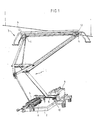
- la figure 1 est une vue simplifiée en perspective d'un pantographe du type unijambiste, équipé d'un dispositif de descente rapide conforme à l'invention ;
- les figures 2 à 4 sont des vues du détail à plus grande échelle de la tête du pantographe ;
- la figure 5 est une vue analogue à la figure 4, montrant le déplacement de l'archet en cas de surcharge frontale ;
- les figures 6 et 7 sont des vues de détail des moyens utilisés pour assurer la libération du ressort de montée ; et
- les figures 8 et 9 sont des vues analogues aux figures 6 et 7, montrant les moyens utilisés pour retendre le ressort après sa libération.
- Figure 1 is a simplified perspective view of a pantograph of the one-legged type, equipped with a rapid descent device according to the invention;
- Figures 2 to 4 are detail views on a larger scale of the head of the pantograph;
- Figure 5 is a view similar to Figure 4 showing the displacement of the bow in the event of frontal overload;
- Figures 6 and 7 are detailed views of the means used to ensure the release of the mounting spring; and
- Figures 8 and 9 are views similar to Figures 6 and 7, showing the means used to tension the spring after its release.
En se référant tout d'abord à la figure 1, on peut voir un pantographe du type unijambiste, constitué essentiellement par un ensemble 1 de cadres articulés venant se fixer sur le toit d'un véhicule à traction électrique, non représenté, par l'intermédiaire d'un châssis 2. Cet ensemble 1 supporte à sa partie supérieure un double archet 3 destiné à venir en contact par frottement avec la caténaire 4.Referring first to FIG. 1, one can see a pantograph of the one-legged type, consisting essentially of a
Le pantographe est équipé de façon classique de deux ressorts de montée 5 et 6 assurant son déploiement. Ces ressorts sont fixés à une extrémité sur le chassis 2 et à l'autre extrémité sur une patte 7 solidaire de l'arbre principal 8 de l'ensemble de cadres articulés 1. Un organe de commande 9, constitué par exemple par un moteur électrique, est par ailleurs prévu pour assurer le repliement à plat du pantographe sur le toit du véhicule porteur, cet organe de commande agissant également sur l'arbre principal 8 par l'intermédiaire d'une biellette 10.The pantograph is conventionally equipped with two rising
Ainsi qu'on peut le voir plus clairement sur les figures 2 à 5, l'archet 3 est fixé sur l'ensemble 1 par l'intermédiaire d'une suspension élastique qui est constituée ici essentiellement de deux pots à ressort tels que 11, dans lesquels l'archet est supporté par des brides telles que 12. Conformément à l'invention, le pantographe est par ailleurs équipé d'un dispositif dit de descente rapide pour déclencher automatiquement la chute du pantographe lorsque l'archet se trouve soumis à une contrainte anormale. Ce dispositif se compose essentiellement d'un système de contacts électriques logé dans la tête du pantographe et formant au moins un interrupteur qui, lorsqu'il se ferme, provoque la détente de l'un des ressorts de montée, en l'occurrence le ressort 5, grâce à des moyens qui seront décrits plus en détail par la suite.As can be seen more clearly in FIGS. 2 to 5, the
Dans l'exemple de réalisation particulier décrit ici, le système de contacts selon l'invention comprend tout d'abord deux premiers contacts 13, 14, solidaires de l'archet 3. Ces contacts sont constitués par des tronçons de tube métallique qui sont fixés à une certaine distance l'un de l'autre et de manière réglable sur la bride 12 supportant l'archet, au moyen de colliers appropriés 15.In the particular embodiment described here, the contact system according to the invention comprises first of all two
Une tige 16 est par ailleurs fixée de manière isolée sur le pot à ressort 11 par l'intermédiaire d'une potence 17. Cette tige est dénudée à ses extrémités et constitue ainsi des deuxièmes contacts 18, 19 qui sont conçus pour coopérer avec les premiers contacts 13, 14 en formant deux interrupteurs normalement ouverts, respectivement 13-18 et 14-19. Pour des raisons de symétrie, le pantographe pourra éventuellement être équipé de l'autre côté d'un système de contacts analogue, disposé entre le second pot à ressort 11 et la bride 12 correspondante.A
Les premiers contacts 13, 14 sont reliés électriquement aux parties de l'archet destinées à venir frotter sur la catenaire 4, soit par des câbles, soit directement par l'intermédiaire de la bride 12. Quant aux deuxièmes contacts 18, 19, ils sont reliés électriquement par un câble 20 à un dispositif de déclenchement électrique 21, visible sur les figures 6 à 9 et qui est apte à provoquer la libération du ressort de montée 5.The
Le système de contacts selon l'invention est complété par un troisième contact tel que 22, situé au voisinage de l'extrémité des cornes 23 de l'archet 3. Ce contact est constitué ici par un plot qui est fixé de manière isolée sur une barre 24 reliant transversalement les deux éléments de l'archet, au niveau de l'extrémité des cornes 23. Un tel contact est prévu de part et d'autre de l'archet et ils sont reliés tous les deux au dispositif de déclenchement électrique 21 par un câble 25.The contact system according to the invention is completed by a third contact such as 22, located in the vicinity of the end of the
En se référant maintenant aux figures 6 à 9, on peut voir que l'extrémité du ressort de montée 5 qui n'est pas reliée à une patte 7, est constituée par une sphère 26 conçue pour venir en prise dans une fourchette 27 montée mobile autour d'un axe 28 supporté par le châssis 2. La fourchette 27 est normalement bloquée en position de retenue du ressort 5 par le dispositif de déclenchement 21 qui est constitué ici par un électro-aimant apte à provoquer l'effacement d'un goujon 29 venant en prise dans une douille 30 solidaire de la fourchette. Pour éviter des problèmes de corrosion, le goujon 29 et la douille 30 seront avantageusement réalisés en acier inoxydable.Referring now to Figures 6 to 9, it can be seen that the end of the
L'extrémité 26 du ressort 5 est par ailleurs prolongée par une tige 31 pourvue à son extrémité d'une butée 32 conçue pour coopérer avec un épaulement 33 ménagé à cet effet sur le châssis 2. La butée 32 est en outre munie d'un filetage 34, dont le but apparaîtra plus clairement par la suite.The
Le dispositif de descente rapide pour pantographe qui vient d'être décrit fonctionne de la manière suivante :
- En cas de surcharge frontale sur le pantographe, par suite d'un incident quelconque, par exemple un obstacle, l'archet 3 pivote dans sa suspension élastique par rapport à l'ensemble de cadres articulés 1 et prend alors la position représentée sur la figure 5. Ce faisant, le
contact 14 solidaire de l'archet vient heurter lecontact 19 solidaire du pot àressort 11, fermant ainsi l'interrupteur 14-19. Par suite, l'électro-aimant 21 se trouve alimenté par le courant de lacatenaire 4, ce qui provoque l'effacement dugoujon 29 retenant lafourchette 27 par sadouille 30. Lafourchette 27 pivote alors autour de sonaxe 28 et libère ainsi l'extrémité 26 du ressort demontée 5 qui se détend jusqu'à ce que labutée 32 prévue à l'extrémité de latige 31 vienne en contact avec l'épaulement 33 duchâssis 2 dans la position illustrée par la figure 7. On notera que ce faisant, le ressort reste guidé par latige 31 et ne risque donc pas de tomber sur le toit du véhicule porteur.
- In the event of a frontal overload on the pantograph, as a result of any incident, for example an obstacle, the
bow 3 pivots in its elastic suspension relative to the set of articulatedframes 1 and then takes the position shown in the figure 5. In doing so, thecontact 14 secured to the bow strikes thecontact 19 secured to thespring pot 11, thus closing the switch 14-19. As a result, theelectromagnet 21 is supplied by the current from thecatenary 4, which causes the erasure of thestud 29 retaining thefork 27 by itssocket 30. Thefork 27 then pivots about itsaxis 28 and releases thus theend 26 of therise spring 5 which relaxes until thestop 32 provided at the end of therod 31 comes into contact with theshoulder 33 of thechassis 2 in the position illustrated in FIG. 7. Note that in doing so, the spring remains guided by therod 31 and therefore does not risk falling on the roof of the carrier vehicle.
Sous l'effet de la détente du ressort 5, le pantographe descend immédiatement de par son poids propre, mais sa chute sur le toit du véhicule porteur est néanmoins amortie, d'une part parce que seulement une partie de la course du ressort est libérée du fait de la présence de la butée 32, et d'autre part parce que l'action du second ressort de montée 6 subsiste entièrement. Le choc peut être ainsi réduit au minimum, afin de ne pas risquer d'endommager le pantographe ou le toit du véhicule.Under the effect of the relaxation of the
Bien entendu, le dispositif selon l'invention fonctionne aussi bien dans les deux sens de marche du véhicule. En se référant à la figure 5, on voit par exemple que si le pantographe subit un choc frontal alors que le véhicule se déplace dans l'autre sens, c'est l'interrupteur formé par les contacts 13 et 18 qui interviendra pour provoquer l'alimentation de l'électro-aimant 21 et par conséquent la descente rapide du pantographe dans les mêmes conditions que précédemment. De plus, il est facile d'ajuster la force de déclenchement du dispositif dans l'un et l'autre sens, en réglant simplement la position des contacts 13 et 14 le long de la. bride 12, au moyen des colliers 15 prévus à cet effet.Of course, the device according to the invention works equally well in the two directions of travel of the vehicle. Referring to FIG. 5, it can be seen for example that if the pantograph is subjected to a frontal impact while the vehicle is moving in the other direction, it is the switch formed by the
En cas de choc latéral sur le pantographe, entraînant un débordement de la catenaire, cette dernière viendra en contact avec l'un des plots 22 disposés aux extrémités des cornes 23 de l'archet, provoquant ainsi l'alimentation de l'électro-aimant 21 et par conséquent la descente du pantographe, toujours dans les mêmes conditions que précédemment. Le pantographe équipé conformément à l'invention se trouve donc protégé à la fois contre des chocs frontaux et des chocs latéraux, et également dans le cas d'un simple débordement latéral de la caténaire.In the event of a side impact on the pantograph, causing the catenary to overflow, the latter will come into contact with one of the
Par ailleurs, comme l'électro-aimant 21 ne peut être alimenté qu'à partir de la caténaire, le dispositif de descente rapide ne peut se déclencher que lorsque celle-ci est sous tension, ce qui évite tout risque de déclenchement inopiné, notamment lorsque des réparations sont effectuées sur le pantographe. Il va de soi en outre que l'électro-aimant 21 pourrait sans inconvénient être remplacé par un autre dispositif assurant la même fonction, par exemple un dispositif pyrotechnique, à condition d'être à déclenchement électri- aue.Furthermore, as the
Lorsque le dispositif de descente rapide selon l'invention a été déclenché, le pantographe peut être facilement remis en service en procédant de la manière illustrée par les figures 8 et 9.When the rapid descent device according to the invention has been triggered, the pantograph can easily be put back into service by proceeding in the manner illustrated in FIGS. 8 and 9.
Pour ce faire, on commence par introduire dans le filetage 34 de la butée 32 une extrémité d'une tige filetée 35 qui est ensuite fixée solidement en place au moyen d'un écrou 36, puis on visse sur l'autre extrémité de la tige un écrou 37 prenant appui sur un support 38 spécialement prévu à cet effet et venant se monter sur le châssis 2. On voit immédiatement qu'en serrant progressivement l'écrou 37, il est possible de retendre le ressort de montée 5 jusqu'à ce que son extrémité 26 vienne à nouveau en prise dans la fourchette 27 qui peut alors être remise en place. Il suffit alors de réarmer l'électro-aimant 21 ou de changer l'élément s'il s'agit d'un dispositif pyrotechnique, puis de procéder au démontage de la tige 35 et du support 38, pour que le dispositif de descente rapide selon l'invention soit à nouveau prêt à fonctionner. On notera en particulier que grâce à cette disposition, il est possible de retendre le ressort de montée dans n'importe quelle position du pantographe, ce qui n'était pas le cas jusqu'à maintenant avec les dispositifs connus qui nécessitaient le plus souvent un démontage complet du pantographe.To do this, we first introduce into the
Bien entendu, la présente invention n'est pas limitée au mode de réalisation qui a été représenté et décrit, et on peut lui apporter de nombreuses modifications sans, pour autant, sorti du cadre des revendications. Il va de soi notamment que cette invention n'est pas limitée aux pantographes unijambistes, ni à un type particulier de suspension de l'archet.Of course, the present invention is not limited to the embodiment which has been shown and described, and numerous modifications can be made to it without, however, departing from the scope of the claims. It goes without saying in particular that this invention is not limited to one-legged pantographs, nor to a particular type of suspension of the bow.
Claims (9)
Priority Applications (1)
| Application Number | Priority Date | Filing Date | Title |
|---|---|---|---|
| AT83440058T ATE25625T1 (en) | 1982-11-30 | 1983-11-28 | AUTOMATIC RAPID LOWERING DEVICE FOR SCISSOR PANTS. |
Applications Claiming Priority (2)
| Application Number | Priority Date | Filing Date | Title |
|---|---|---|---|
| FR8220172A FR2536707B1 (en) | 1982-11-30 | 1982-11-30 | FAST AUTOMATIC LOWERING DEVICE FOR PANTOGRAPHER |
| FR8220172 | 1982-11-30 |
Publications (2)
| Publication Number | Publication Date |
|---|---|
| EP0112265A1 EP0112265A1 (en) | 1984-06-27 |
| EP0112265B1 true EP0112265B1 (en) | 1987-03-04 |
Family
ID=9279705
Family Applications (1)
| Application Number | Title | Priority Date | Filing Date |
|---|---|---|---|
| EP83440058A Expired EP0112265B1 (en) | 1982-11-30 | 1983-11-28 | Automatic fast lowering device for a pantograph |
Country Status (4)
| Country | Link |
|---|---|
| EP (1) | EP0112265B1 (en) |
| AT (1) | ATE25625T1 (en) |
| DE (1) | DE3369930D1 (en) |
| FR (1) | FR2536707B1 (en) |
Families Citing this family (10)
| Publication number | Priority date | Publication date | Assignee | Title |
|---|---|---|---|---|
| DE3431011C2 (en) * | 1984-08-23 | 1994-05-19 | Ibeg Masch & Geraetebau | Pantographs for electric traction vehicles |
| DE3828889C2 (en) * | 1988-08-25 | 1997-10-02 | Dozler Gmbh | Pantograph |
| US5124510A (en) * | 1990-08-16 | 1992-06-23 | Marvin Garfinkle | Tracking pantograph for railway electrification |
| GB9930182D0 (en) * | 1999-12-22 | 2000-02-09 | Brecknell Willis & Co Ltd | Pantographs |
| CN101531141B (en) * | 2009-04-24 | 2011-01-26 | 田耕 | Charging contact device of electric automobile and automatic rapid charging station |
| CN101856975B (en) * | 2010-04-30 | 2012-05-02 | 北京赛德高科铁道电气科技有限责任公司 | Pantograph control device |
| CN104325890B (en) * | 2014-11-28 | 2016-03-02 | 南车株洲电力机车有限公司 | The bow lock-out circuit of a kind of both-end cab DC electric locomotive |
| CN107618374A (en) * | 2017-09-26 | 2018-01-23 | 沈阳新阳光机电科技有限公司 | Annular pantograph and tramcar |
| FR3104080B1 (en) * | 2019-12-10 | 2024-03-15 | Sncf Reseau | Pantograph of a car of rolling stock adapted to capture current from an electrical supply line |
| CN111823871B (en) * | 2020-07-30 | 2022-01-18 | 中车株洲电力机车有限公司 | Upper part current-collecting device |
Family Cites Families (5)
| Publication number | Priority date | Publication date | Assignee | Title |
|---|---|---|---|---|
| CH111266A (en) * | 1924-11-05 | 1925-08-01 | Fischer Hermann | Device in electric railways for operating the pantograph of rail vehicles. |
| CH120422A (en) * | 1926-03-04 | 1927-05-16 | Meyfarth Gottlieb | Pantographs for electric vehicles. |
| DE835463C (en) * | 1950-10-11 | 1952-03-31 | Theodor Steinfurth Dipl Ing | Automatic lay-down device for pantographs of electric vehicles |
| DE1106363B (en) * | 1959-09-26 | 1961-05-10 | Bochumer Ver Fuer Gussstahlfab | Device for the automatic retraction of the pantograph stirrups of electric traction vehicles |
| FR2484929A1 (en) * | 1980-06-18 | 1981-12-24 | Faiveley Sa | RETRACTABLE PANTOGRAPH IN CASE OF ABNORMAL FRONT EFFORT |
-
1982
- 1982-11-30 FR FR8220172A patent/FR2536707B1/en not_active Expired
-
1983
- 1983-11-28 DE DE8383440058T patent/DE3369930D1/en not_active Expired
- 1983-11-28 AT AT83440058T patent/ATE25625T1/en not_active IP Right Cessation
- 1983-11-28 EP EP83440058A patent/EP0112265B1/en not_active Expired
Also Published As
| Publication number | Publication date |
|---|---|
| FR2536707A1 (en) | 1984-06-01 |
| ATE25625T1 (en) | 1987-03-15 |
| EP0112265A1 (en) | 1984-06-27 |
| DE3369930D1 (en) | 1987-04-09 |
| FR2536707B1 (en) | 1985-08-23 |
Similar Documents
| Publication | Publication Date | Title |
|---|---|---|
| EP0406130B1 (en) | Limiting circuit-breaker provided with electromagnetic means for delaying the return movement of the contact | |
| EP0112265B1 (en) | Automatic fast lowering device for a pantograph | |
| FR2578354A1 (en) | CIRCUIT BREAKER THAT CAN OPERATE AS A SWITCH | |
| EP1347479B1 (en) | Ultrafast current limiting electrical switching apparatus | |
| FR2693589A1 (en) | Safety device for electric vehicle openings, of the type with cable for driving a movable member, in particular window glass and sunroofs. | |
| EP0848404B1 (en) | Selective tripping block for multipole circuit breaker | |
| EP1815569B1 (en) | Overvoltage-protection device with improved disconnection | |
| FR2559308A1 (en) | CONTACT EQUIPPED WITH A MAGNETIC COMPENSATOR WITH ADJUSTABLE RELEASE THRESHOLD AND CONTACTOR-CIRCUIT BREAKER USING SUCH CONTACT | |
| CA2251240C (en) | Lightning arrestor arrangement for elevated electricity transmission line with fault indicator for lightning arrestor | |
| FR2796202A1 (en) | CIRCUIT BREAKER MECHANISM | |
| EP0013779B1 (en) | Vehicle safety circuit breaker | |
| EP2733719B1 (en) | Auxiliary tripping device for tripping a circuit breaker | |
| EP0579518B1 (en) | Electric vehicle window actuator employing a cable sliding along a guide rail | |
| FR2746957A1 (en) | CONTROL MECHANISM OF A CIRCUIT BREAKER WITH WIDE OPENING ANGLE | |
| CH620644A5 (en) | ||
| EP0130208B1 (en) | Switch with controlled closing and opening and automatic opening in case of current overloads | |
| FR2839196A1 (en) | Current security limiter circuit breaker contact mechanism having isolating container with rotating switching shaft having symmetrical springs and contact bridge contacting via control cams. | |
| FR2819545A1 (en) | Roller shutter has obstacle detector in lower slat with switch to cut out drive motor | |
| EP0054499B1 (en) | Circuit breaker with neutral-line disconnection | |
| EP1069585B1 (en) | Electromagnetic switch mechanism with manual reset device | |
| EP1798130B1 (en) | Safety device for a cable transport installation | |
| EP0037295B1 (en) | High-speed circuit breaker provided with a shock-proof device | |
| FR2534080A1 (en) | APPARATUS FOR AUTOMATIC EARTHING OF ACCIDENTALLY LIVE STRUCTURES | |
| FR2559307A1 (en) | CONTACT EQUIPPED WITH A SELFIBERABLE MAGNETIC COMPENSATOR FROM A COMPENSATING FORCE THRESHOLD, AND CONTACTOR-CIRCUIT BREAKER USING SUCH CONTACT | |
| FR2496976A1 (en) | Direct acting overcurrent release for circuit breaker - has spring loaded hinged linkage to give short time delay in trip operation |
Legal Events
| Date | Code | Title | Description |
|---|---|---|---|
| PUAI | Public reference made under article 153(3) epc to a published international application that has entered the european phase |
Free format text: ORIGINAL CODE: 0009012 |
|
| AK | Designated contracting states |
Designated state(s): AT BE CH DE GB IT LI LU NL SE |
|
| 17P | Request for examination filed |
Effective date: 19841207 |
|
| 17Q | First examination report despatched |
Effective date: 19860116 |
|
| RAP1 | Party data changed (applicant data changed or rights of an application transferred) |
Owner name: STEMMANN-TECHNIK GMBH |
|
| GRAA | (expected) grant |
Free format text: ORIGINAL CODE: 0009210 |
|
| AK | Designated contracting states |
Kind code of ref document: B1 Designated state(s): AT BE CH DE GB IT LI LU NL SE |
|
| REF | Corresponds to: |
Ref document number: 25625 Country of ref document: AT Date of ref document: 19870315 Kind code of ref document: T |
|
| ITF | It: translation for a ep patent filed |
Owner name: STUDIO CONS. BREVETTUALE S.R.L. |
|
| REF | Corresponds to: |
Ref document number: 3369930 Country of ref document: DE Date of ref document: 19870409 |
|
| PG25 | Lapsed in a contracting state [announced via postgrant information from national office to epo] |
Ref country code: LU Free format text: LAPSE BECAUSE OF NON-PAYMENT OF DUE FEES Effective date: 19871130 |
|
| PLBE | No opposition filed within time limit |
Free format text: ORIGINAL CODE: 0009261 |
|
| STAA | Information on the status of an ep patent application or granted ep patent |
Free format text: STATUS: NO OPPOSITION FILED WITHIN TIME LIMIT |
|
| 26N | No opposition filed | ||
| PGFP | Annual fee paid to national office [announced via postgrant information from national office to epo] |
Ref country code: AT Payment date: 19901023 Year of fee payment: 8 |
|
| PGFP | Annual fee paid to national office [announced via postgrant information from national office to epo] |
Ref country code: LU Payment date: 19901115 Year of fee payment: 8 |
|
| PGFP | Annual fee paid to national office [announced via postgrant information from national office to epo] |
Ref country code: GB Payment date: 19901126 Year of fee payment: 8 |
|
| ITTA | It: last paid annual fee | ||
| PGFP | Annual fee paid to national office [announced via postgrant information from national office to epo] |
Ref country code: SE Payment date: 19901130 Year of fee payment: 8 Ref country code: NL Payment date: 19901130 Year of fee payment: 8 Ref country code: DE Payment date: 19901130 Year of fee payment: 8 |
|
| PGFP | Annual fee paid to national office [announced via postgrant information from national office to epo] |
Ref country code: BE Payment date: 19901211 Year of fee payment: 8 |
|
| PGFP | Annual fee paid to national office [announced via postgrant information from national office to epo] |
Ref country code: CH Payment date: 19910128 Year of fee payment: 8 |
|
| EPTA | Lu: last paid annual fee | ||
| PG25 | Lapsed in a contracting state [announced via postgrant information from national office to epo] |
Ref country code: GB Effective date: 19911128 Ref country code: AT Effective date: 19911128 |
|
| PG25 | Lapsed in a contracting state [announced via postgrant information from national office to epo] |
Ref country code: SE Effective date: 19911129 |
|
| PG25 | Lapsed in a contracting state [announced via postgrant information from national office to epo] |
Ref country code: LI Effective date: 19911130 Ref country code: CH Effective date: 19911130 Ref country code: BE Effective date: 19911130 |
|
| BERE | Be: lapsed |
Owner name: STEMMANN-TECHNIK G.M.B.H. Effective date: 19911130 |
|
| PG25 | Lapsed in a contracting state [announced via postgrant information from national office to epo] |
Ref country code: NL Effective date: 19920601 |
|
| NLV4 | Nl: lapsed or anulled due to non-payment of the annual fee | ||
| GBPC | Gb: european patent ceased through non-payment of renewal fee | ||
| REG | Reference to a national code |
Ref country code: CH Ref legal event code: PL |
|
| PG25 | Lapsed in a contracting state [announced via postgrant information from national office to epo] |
Ref country code: DE Effective date: 19920801 |
|
| EUG | Se: european patent has lapsed |
Ref document number: 83440058.2 Effective date: 19920604 |