EP0112198B1 - Kontroll- und Regeleinrichtung für den Öffnungsquerschnitt einer Schubdüse - Google Patents
Kontroll- und Regeleinrichtung für den Öffnungsquerschnitt einer Schubdüse Download PDFInfo
- Publication number
- EP0112198B1 EP0112198B1 EP83402152A EP83402152A EP0112198B1 EP 0112198 B1 EP0112198 B1 EP 0112198B1 EP 83402152 A EP83402152 A EP 83402152A EP 83402152 A EP83402152 A EP 83402152A EP 0112198 B1 EP0112198 B1 EP 0112198B1
- Authority
- EP
- European Patent Office
- Prior art keywords
- nozzle
- actuator
- piston
- emergency
- pressure
- Prior art date
- Legal status (The legal status is an assumption and is not a legal conclusion. Google has not performed a legal analysis and makes no representation as to the accuracy of the status listed.)
- Expired
Links
Images


Classifications
-
- F—MECHANICAL ENGINEERING; LIGHTING; HEATING; WEAPONS; BLASTING
- F02—COMBUSTION ENGINES; HOT-GAS OR COMBUSTION-PRODUCT ENGINE PLANTS
- F02K—JET-PROPULSION PLANTS
- F02K1/00—Plants characterised by the form or arrangement of the jet pipe or nozzle; Jet pipes or nozzles peculiar thereto
- F02K1/06—Varying effective area of jet pipe or nozzle
- F02K1/15—Control or regulation
- F02K1/16—Control or regulation conjointly with another control
- F02K1/17—Control or regulation conjointly with another control with control of fuel supply
-
- F—MECHANICAL ENGINEERING; LIGHTING; HEATING; WEAPONS; BLASTING
- F02—COMBUSTION ENGINES; HOT-GAS OR COMBUSTION-PRODUCT ENGINE PLANTS
- F02K—JET-PROPULSION PLANTS
- F02K1/00—Plants characterised by the form or arrangement of the jet pipe or nozzle; Jet pipes or nozzles peculiar thereto
- F02K1/06—Varying effective area of jet pipe or nozzle
- F02K1/15—Control or regulation
Definitions
- the present invention relates to a device for controlling and regulating the opening section of a propellant nozzle.
- Aviation turbojet engines are already known, for example, equipped with a main regulator which under normal conditions regulates the flow of fuel sent to the combustion chambers, and an auxiliary regulator or emergency regulator which the pilot can replace the regulator. main in the event of its failure, to allow a continuation of the flight to the nearest terrain.
- FR-A 1 514 925 describes a device for controlling an adjustable nozzle in which in the event of a failure of a primary device, the latter is locked in a determined position and an intervention by the pilot controls a secondary device for rescue.
- US A-2 834182 describes a nozzle control system comprising an emergency circuit in the event of failure of the main electrical circuit. This emergency circuit, initiated by the pilot, controls a power distributor for the control jack.
- the invention provides a solution to the problem which the automatic obtaining of a sufficient propulsion thrust can pose when passing over the flight with an emergency regulator in service, avoiding any direct manual intervention by the pilot at the nozzle control device. .
- the gear switching members normal in emergency operation include a drawer or equivalent member which cooperates with a conduit connected to at least one orifice that comprises the jack, or one of them when there are several, in addition to its supply pipes supplying the opening and closing pressures of the nozzle, so that, depending on the position of the cylinder piston, the orifice is sometimes closed, sometimes uncovered, establishing communication with one or other of the chambers of the cylinder while the drawer closes said conduit during normal operation and instead puts it in the exhaust towards the return of the pump of the supply system during emergency operation, so that the differential pressure generated in the hydraulic cylinder lique controls the back-up nozzle, the section of the nozzle taking an intermediate value which automatically provides the engine with sufficient thrust while avoiding the risk of compressor pumping.
- Another characteristic of the invention consists in that the drawer can receive, by a maneuver of the pilot at the start of the above-mentioned switching, a momentary command keeping it in its normal operating position, so that the actuator is then put or remains in the position corresponding to the full opening of the nozzle to facilitate re-ignition of the combustion chambers if necessary.
- the hydraulic fluid used to control the cylinders is preferably the fuel itself, under the pressure supplied by the pump of the main regulator during normal operation or under the pressure supplied by the pump of the emergency regulator, when rescue.
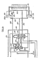
- FIGS. 1 and 1a respectively represent, on the one hand, a regulator as described in the document FR-A-2406079 recalled above and the device for regulating the nozzle section combined with this regulator, according to an embodiment of the invention; the pipes shown in these figures are connected to the points which are marked a, b, c, d and e.
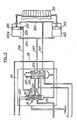
- FIG. 2 is a view similar to FIG. 1a, the members being in the position they occupy when the emergency regulator is in service, the combustion chambers of the turbojet engine being ignited.
- FIGS. 3 and 4 are detailed views of the piston of the pilot cylinder and of the regulation orifices which it controls.
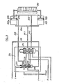
- FIG. 5 shows a variant of the device shown in FIGS. 1a and 2.
- Figure 8 schematically shows the device of Figure 7 in another operating position.
- FIG. 7 of the Applicant's French patent 77.30486 publication number 2 406 079 has been reproduced, with a few modifications which will result from the description below, while retaining the reference numbers already used in said FIG. patent, which will facilitate the identification of organs.
- the main regulator with its pump 52 in 65 the fuel flow line to the injectors of the combustion chambers, in 14 the emergency regulator with its pump 1, in 16 the valve with rotary plug 80 whose the pilot controls the rotation by the electric motor 17 when the pilot wants to control the standby flow, at 55 the transformer with mobile drawer 56, which, depending on the position it occupies, routes the fuel discharged by the pump of the main regulator 51 towards the injectors of the combustion chambers, then putting the line 64 intended for the supply of the fuel supplied by the emergency pump 1 back to 102, or vice versa (in the drawing the drawer 56 is shown in the position where the regulator main 51 with its pump 52 is in service).
- valve which can either return the discharge of the emergency pump 1 upstream of the valve 80 (it is the position of the valve valve 7 which is shown in Figure 1), or isolate the return flow so that the high pressure supplied by the emergency pump becomes active.
- a movable slide actuated by the pressure taken by the piping 69 on the discharge of the pump 1 and, in opposition, by the spring 70 and by the pressure taken in the piping 95 downstream of the electromagnetic valve 77. This valve is normally closed. It is opened by the pilot when he wants to put the emergency regulator into service.
- the device for regulating the section of the nozzle connected according to a, b, c will now be described with reference to FIG. 1a.
- the members are also in the position where the regulation is carried out by the main regulator.
- FIG. 1a there is shown schematically in 201 all of the movable flaps used to adjust the useful section of the nozzle of a turbojet.
- the constitution of such a device, capable of numerous variants, is in itself well known and does not need to be described in detail.
- a set of hydraulic cylinders distributed around the axis of the nozzle and each actuating a flap or a group of flaps.
- These various jacks supplied in parallel are of usual construction, as shown for jack 202, with a pipe 203 for the admission of the opening pressure of the nozzle designated hereinafter by POT and a pipe 204 for the admission of the nozzle closing pressure designated by PFT, In this way, a displacement of the piston 205 of the cylinders, from right to left of FIG. 1a, corresponds to the opening of the nozzle, while a displacement of the left to right corresponds to the closure.
- One of the jacks 202p playing the role of pilot jack, is shown in the upper part of FIG. 1a. It is also connected like the others to the pipes 203 and 204, but also comprises in an intermediate zone of its wall, suitably chosen, two holes 206-207, for example staggered on a generator, at an interval adapted to the thickness of the piston, so that in a certain position thereof it simultaneously closes these two holes. These are both connected to a pipe 208 which, by the operation of a drawer 209, can either be closed at 210 (FIG. 1a) therefore put out of action, or connected by 211 (FIG. 2) with the return of the pumps.
- a pipe 208 which, by the operation of a drawer 209, can either be closed at 210 (FIG. 1a) therefore put out of action, or connected by 211 (FIG. 2) with the return of the pumps.
- a kind of switching 214 which has the function of substituting for the pressures supplied by the main regulator 51, for the control of the nozzle cylinders 202 (pressures POT and PFT), those supplied by the emergency regulator 14 when the latter is put into action, and vice versa.
- the electromagnetic valve 77 is closed, so that the chamber 70a is brought to the same pressure as the chamber 68 via the orifice 76.
- the slide 67 occupies the position (shown in FIG. 1) for which it returns the tubing 66 connected at a to 212 the pipe 218.
- the switching device 214 the slide 219 of the transformer 220 is placed, by its spring 221, in the figured position for which the pipes 203 and 204 of the jacks are supplied by the main regulator 51 of which the pressure outputs are connected at points d and e.
- the drawer 209 is put by its spring 222 in the figured position where it closes the tube 208 leading to the holes 206 and 207 of the pilot cylinder 202p. These holes therefore remain out of action and the regulation of the nozzle is carried out according to the laws which are specific to the main regulator.
- the nozzle can be and remain wide open, which corresponds to the position of the pistons 205 shown in FIG. 1a.
- the drawer 219 then cuts the communication of the pipes 203 and 204 with the main regulator and, on the contrary, allows the fuel discharged at c by the emergency pump to pass towards these pipes through the orifices 223 and 224 unmasked by the drawer 209.
- the nozzle is fully open, which corresponds to the position of the pistons 205 of the jacks shown in FIG. La, the fuel arriving through the piping 203 and that filling the right chambers of the jacks can leak through the piping 208 towards the return 211.
- the action of the PFT pressure becomes preponderant compared to the POT pressure and the jacks reduce the section of the nozzle allowing an increase in the thrust.
- the closing movement continues until the piston of the pilot cylinder comes to the right of the holes 206 and 207 by closing them.
- the arrangement of the two successive bores has the advantage of ensuring a precise position of the jack whatever the direction of the forces on the rod.
- the plug 80 is placed in a position such that it feeds the pipe 18 through the lights 82 and the tap 77 is opened with electromagnetic control to produce the opening of the valve 92 sending fuel to the ignition injectors of the chambers. combustion.
- the fuel sent to b maintains the pressure above the drawer 209, so that the pressures above and below this drawer being approximately equal the spring 222 keeps the drawer 209 in the position of FIG. 1a, while the drawer 219 has taken the position of FIG. 2.
- the nozzle is then completely open for re-ignition.
- the through holes 223, 224 of the emergency fuel, controlled by the slide 209, are provided with diaphragms. These diaphragms are useful for adjusting the speed of movement of the flaps of the nozzle during transient movements and their section is adjusted for this purpose.
- the orifices 206 and 207 are completely closed, their interval being for this purpose suitably adapted to the thickness of the piston.
- the pressures POT and PFT are then both equal to the pressure supplied by the emergency pump in c.
- the wall of the pilot cylinder 202p does not includes only a hole 206.
- the transformer 219 is unchanged, as is the piping circuit.
- the slide 209 is modified by the arrangement of an axial channel 209a which, in its emergency operating position shown in FIG. 5, puts back the pressure POT.
- the slide valve 219 of the transformer and the slide valve 209 being in the position shown in FIG. 5, the PFT pressure is connected by c to the discharge pressure of the emergency pump, while the POT pressure is connected to the return by the axial hole 209a of the slide 209.
- the flaps of the nozzle therefore move towards the closure until the piston of the pilot cylinder passes to the right of the hole 206 as shown in FIG. 5.
- the pressure PFT leaks back and the leakage rate, through the diaphragm passage 224, generates a pressure drop which reduces the PFT pressure until the piston of the pilot cylinder and, consequently, the flaps of the nozzle.
- the cylinder of the pilot cylinder 202p does not have a bore on its wall.
- a tube 225 fixed on the bottom of the cylinder, and penetrating into an axial bore 226 of the piston and its rod, the external surface of the tube 225 and the surface of the bore 226 being adapted to each other, for example by running in, so as to minimize fluid leakage between the tube and the bore while allowing movement of the piston relative to the tube without excessive friction.
- the tube 225 is pierced with an orifice 227 which can be closed or uncovered by the piston 205 in the movement of this piston.
- the device can be modified as shown in FIG. 7.
- the tube 225 is not pierced laterally but its freely open end 228 cooperates with a small piston 229, disposed in a bore 226 of the piston rod of the pilot cylinder, a bore which is in communication via a channel 230 with the chamber located to the right of the piston which receives the POT pressure, which thus prevails in the bore 226 to the right of the small auxiliary piston 229.
- the piston 229 can play inside the bore 226 to allow the continuation of the movement of the piston 205 to the left after the end 228 of the tube 225 has come into application on the piston 229. Or when the piston 205 moves to the right for closing the nozzle, the valve formed by the end 228 of the tube 225 and the piston 229 remains closed at the start of this movement, as shown in the diagram in FIG. 8. The piston 229 remains fixed until said piston comes into abutment against the internal shoulder 231 of the main piston 205, moment from which the end 228 of the tube 225 is uncovered allowing the pressure to drop in the left chamber of the jack, as shown in figure 7.
Claims (6)
mit wenigstens einer hydraulischen Zylinderanordnung, die auf wenigstens ein bewegliches Organ einwirkt, durch dessen Verschiebung der Querschnitt der Schubdüse veränderbar ist,
mit einem ersten System zur Speisung der Zylinderanordnung mit unter Druck stehender Hydraulikflüssigkeit für den Normalbetrieb und einem zweiten Speisesystem, das für den Notbetrieb dient,
dadurch gekennzeichnet,
daß die Organe zur Umschaltung von Normalbetrieb auf Notbetrieb einen Schieber (209) oder ein gleichwirkendes Organ umfassen, das mit einer Leitung (208) zusammenwirkt, die mit wenigstens einer in der Zylinderanordnung oder, falls mehrere Zylinderanordnungen vorhanden sind, in einer der Zylinderanordnungen ausgebildeten Öffnung (206, 207) verbunden ist und die diese Zylinderanordnung zusätzlich zu ihren Speiseleitungen besitzt, die den Öffnungsdruck (POT) und den Schließdruck (PFT) für die Schubdüse liefern, wobei diese Öffnung (206, 207) derart angeordnet ist, daß sie je nach Position des Kolbens (205) der Zylinderanordnung fallweise verschlossen oder geöffnet ist und dabei die Verbindung mit der einen oder der anderen Kammer der Zylinderanordnung herstellt, während der Schieber (209) die genannte Leitung (208) bei Normalbetrieb verschließt, sie hingegen bei Notbetrieb an den Auslaß zum Rücklauf der Pumpe des Speisesystems legt, so daß der in der hydraulischen Zylinderanordnung erzeugte Differenzdruck die Schubdüse in den Notbetrieb steuert, wobei der Querschnitt der Schubdüse einen Mittelwert annimmt, der dem Motor automatisch eine ausreichende Schubkraft sichert, dabei jedoch die Gefahr ausschaltet, daß der Verdichter um die Nenndrehzahl pendelt ("pumpt").
Applications Claiming Priority (2)
| Application Number | Priority Date | Filing Date | Title |
|---|---|---|---|
| FR8219949 | 1982-11-29 | ||
| FR8219949A FR2536793A1 (fr) | 1982-11-29 | 1982-11-29 | Dispositif de commande et de regulation de la section d'ouverture d'une tuyere propulsive |
Publications (2)
| Publication Number | Publication Date |
|---|---|
| EP0112198A1 EP0112198A1 (de) | 1984-06-27 |
| EP0112198B1 true EP0112198B1 (de) | 1986-09-03 |
Family
ID=9279601
Family Applications (1)
| Application Number | Title | Priority Date | Filing Date |
|---|---|---|---|
| EP83402152A Expired EP0112198B1 (de) | 1982-11-29 | 1983-11-07 | Kontroll- und Regeleinrichtung für den Öffnungsquerschnitt einer Schubdüse |
Country Status (4)
| Country | Link |
|---|---|
| US (1) | US4501117A (de) |
| EP (1) | EP0112198B1 (de) |
| DE (1) | DE3365895D1 (de) |
| FR (1) | FR2536793A1 (de) |
Families Citing this family (1)
| Publication number | Priority date | Publication date | Assignee | Title |
|---|---|---|---|---|
| RU2634506C1 (ru) * | 2016-12-15 | 2017-10-31 | Публичное Акционерное Общество "Уфимское Моторостроительное Производственное Объединение" (Пао "Умпо") | Способ регулирования авиационного турбореактивного двигателя |
Citations (1)
| Publication number | Priority date | Publication date | Assignee | Title |
|---|---|---|---|---|
| FR2406079A1 (fr) * | 1977-10-11 | 1979-05-11 | Snecma | Dispositif de regulation de turbine a gaz |
Family Cites Families (8)
| Publication number | Priority date | Publication date | Assignee | Title |
|---|---|---|---|---|
| US2726507A (en) * | 1952-01-14 | 1955-12-13 | Solar Aircraft Co | Jet power plant controls |
| US2818703A (en) * | 1954-07-01 | 1958-01-07 | Gen Electric | Jet engine fuel, pressure ratio, and nozzle area control |
| US2834182A (en) * | 1955-06-21 | 1958-05-13 | Charles H Culbertson | High altitude compensation of two position exhaust nozzle control |
| FR1295470A (fr) * | 1961-04-25 | 1962-06-08 | Procédés et dispositifs pour fabriquer des blocs de propergols solides, notamment pour fusées | |
| DE1287862B (de) * | 1963-09-26 | 1969-01-23 | ||
| FR1395470A (fr) * | 1964-05-25 | 1965-04-09 | Dowty Fuel Syst Ltd | Système de commande pour turbine à gaz d'avion |
| US4137707A (en) * | 1977-07-22 | 1979-02-06 | General Electric Company | Integrated control system for a gas turbine engine |
| US4142364A (en) * | 1977-07-22 | 1979-03-06 | General Electric Company | Back-up control for gas turbine engine |
-
1982
- 1982-11-29 FR FR8219949A patent/FR2536793A1/fr active Granted
-
1983
- 1983-11-07 DE DE8383402152T patent/DE3365895D1/de not_active Expired
- 1983-11-07 EP EP83402152A patent/EP0112198B1/de not_active Expired
- 1983-11-16 US US06/552,383 patent/US4501117A/en not_active Expired - Lifetime
Patent Citations (1)
| Publication number | Priority date | Publication date | Assignee | Title |
|---|---|---|---|---|
| FR2406079A1 (fr) * | 1977-10-11 | 1979-05-11 | Snecma | Dispositif de regulation de turbine a gaz |
Also Published As
| Publication number | Publication date |
|---|---|
| US4501117A (en) | 1985-02-26 |
| DE3365895D1 (en) | 1986-10-09 |
| EP0112198A1 (de) | 1984-06-27 |
| FR2536793A1 (fr) | 1984-06-01 |
| FR2536793B1 (de) | 1985-03-08 |
Similar Documents
| Publication | Publication Date | Title |
|---|---|---|
| CA2813923C (fr) | Dispositif de lubrification avec vanne de derivation | |
| CA2332471C (fr) | Dispositif et procede de regulation de pression et debit de carburant d'alimentation d'une unite de servovannes | |
| EP2486261A1 (de) | Schaltung zur zuführung von kraftstoff an ein flugzeugtriebwerk | |
| FR2637942A1 (fr) | Vanne de distribution de carburant, notamment pour turbomoteur, et procede de fonctionnement d'un tel turbomoteur | |
| CA2619921A1 (fr) | Injecteur de carburant a deux etages | |
| CA2619352C (fr) | Dispositif d'injection de carburant dans une turbomachine | |
| FR2467752A1 (fr) | Systeme de freinage hydraulique | |
| EP0689006B1 (de) | Verfahren und Vorrichtung zur Kraftstoffversorgung und zur Kühlung der Abflugdüse in einer Brennkammer mit zwei Brennerköpfen | |
| FR2692658A1 (fr) | Dispositif pour la commande d'au moins un dispositif directeur, commandant le passage d'air de combustion, d'un brûleur pour mécanismes moteurs à turbine à gaz. | |
| EP0031770A1 (de) | Aufgeladene Brennkraftmaschine, insbesondere Dieselmotor | |
| EP0227495B1 (de) | Steuervorrichtung für lenkbare Flugkörper mittels seitlicher Düsen | |
| FR3079879A1 (fr) | Vanne de decharge a ouverture regulee | |
| EP0112198B1 (de) | Kontroll- und Regeleinrichtung für den Öffnungsquerschnitt einer Schubdüse | |
| EP0591018A1 (de) | Lichtbogenplasmabrenner und Verfahren zu seiner Anwendung | |
| FR2672944A1 (fr) | Distributeur proportionnel et ensemble de commande d'une pluralite de recepteurs hydrauliques comportant pour chaque recepteur un tel distributeur. | |
| FR2618528A1 (fr) | Perfectionnements aux chambres de combustion auxiliaires, pour moteurs a combustion interne suralimentes, et moteurs a combustion interne equipes d'une telle chambre | |
| FR2890691A1 (fr) | "systeme de commande du debit de combustible pour un appareil de rechauffage de moteur a turbine a gaz" | |
| EP0278814B1 (de) | Kraftstoffregler für Turbomaschinen | |
| EP0582497B1 (de) | Steuervorrichtung für mehrere hydraulische Verbraucher | |
| FR2711433A1 (fr) | Régulateur coaxial de débit. | |
| FR2985284A1 (fr) | Dispositif pour la commande du calage des pales d'une helice | |
| FR2718190A1 (fr) | Soupape de régulation d'injection de carburant pour une turbomachine. | |
| FR2468775A1 (fr) | Distributeur hydraulique | |
| EP0434531B1 (de) | Einrichtung zur automatischen Bewegungsumkehr eines doppelt wirkenden Hydraulikstellgliedes | |
| EP0635679B1 (de) | Einspritz- und Regelvorrichtung für atmosphärische Gasbrenner von Heizgeräte, insbesondere der Infrarottyp |
Legal Events
| Date | Code | Title | Description |
|---|---|---|---|
| PUAI | Public reference made under article 153(3) epc to a published international application that has entered the european phase |
Free format text: ORIGINAL CODE: 0009012 |
|
| 17P | Request for examination filed |
Effective date: 19831117 |
|
| AK | Designated contracting states |
Designated state(s): DE FR GB IT SE |
|
| ITF | It: translation for a ep patent filed |
Owner name: BARZANO' E ZANARDO MILANO S.P.A. |
|
| GRAA | (expected) grant |
Free format text: ORIGINAL CODE: 0009210 |
|
| AK | Designated contracting states |
Kind code of ref document: B1 Designated state(s): DE FR GB IT SE |
|
| REF | Corresponds to: |
Ref document number: 3365895 Country of ref document: DE Date of ref document: 19861009 |
|
| PLBE | No opposition filed within time limit |
Free format text: ORIGINAL CODE: 0009261 |
|
| STAA | Information on the status of an ep patent application or granted ep patent |
Free format text: STATUS: NO OPPOSITION FILED WITHIN TIME LIMIT |
|
| 26N | No opposition filed | ||
| REG | Reference to a national code |
Ref country code: FR Ref legal event code: CL |
|
| ITTA | It: last paid annual fee | ||
| EAL | Se: european patent in force in sweden |
Ref document number: 83402152.9 |
|
| PGFP | Annual fee paid to national office [announced via postgrant information from national office to epo] |
Ref country code: SE Payment date: 20011008 Year of fee payment: 19 |
|
| PGFP | Annual fee paid to national office [announced via postgrant information from national office to epo] |
Ref country code: FR Payment date: 20011023 Year of fee payment: 19 |
|
| PGFP | Annual fee paid to national office [announced via postgrant information from national office to epo] |
Ref country code: GB Payment date: 20011107 Year of fee payment: 19 |
|
| PGFP | Annual fee paid to national office [announced via postgrant information from national office to epo] |
Ref country code: DE Payment date: 20011129 Year of fee payment: 19 |
|
| REG | Reference to a national code |
Ref country code: GB Ref legal event code: IF02 |
|
| REG | Reference to a national code |
Ref country code: FR Ref legal event code: TP Ref country code: FR Ref legal event code: CD |
|
| PG25 | Lapsed in a contracting state [announced via postgrant information from national office to epo] |
Ref country code: GB Free format text: LAPSE BECAUSE OF NON-PAYMENT OF DUE FEES Effective date: 20021107 |
|
| PG25 | Lapsed in a contracting state [announced via postgrant information from national office to epo] |
Ref country code: SE Free format text: LAPSE BECAUSE OF NON-PAYMENT OF DUE FEES Effective date: 20021108 |
|
| PG25 | Lapsed in a contracting state [announced via postgrant information from national office to epo] |
Ref country code: DE Free format text: LAPSE BECAUSE OF NON-PAYMENT OF DUE FEES Effective date: 20030603 |
|
| GBPC | Gb: european patent ceased through non-payment of renewal fee | ||
| EUG | Se: european patent has lapsed | ||
| PG25 | Lapsed in a contracting state [announced via postgrant information from national office to epo] |
Ref country code: FR Free format text: LAPSE BECAUSE OF NON-PAYMENT OF DUE FEES Effective date: 20030731 |
|
| REG | Reference to a national code |
Ref country code: FR Ref legal event code: ST |