EP0112198B1 - Control and regulation apparatus for the opening section of a propulsive nozzle - Google Patents
Control and regulation apparatus for the opening section of a propulsive nozzle Download PDFInfo
- Publication number
- EP0112198B1 EP0112198B1 EP83402152A EP83402152A EP0112198B1 EP 0112198 B1 EP0112198 B1 EP 0112198B1 EP 83402152 A EP83402152 A EP 83402152A EP 83402152 A EP83402152 A EP 83402152A EP 0112198 B1 EP0112198 B1 EP 0112198B1
- Authority
- EP
- European Patent Office
- Prior art keywords
- nozzle
- actuator
- piston
- emergency
- pressure
- Prior art date
- Legal status (The legal status is an assumption and is not a legal conclusion. Google has not performed a legal analysis and makes no representation as to the accuracy of the status listed.)
- Expired
Links
Images


Classifications
-
- F—MECHANICAL ENGINEERING; LIGHTING; HEATING; WEAPONS; BLASTING
- F02—COMBUSTION ENGINES; HOT-GAS OR COMBUSTION-PRODUCT ENGINE PLANTS
- F02K—JET-PROPULSION PLANTS
- F02K1/00—Plants characterised by the form or arrangement of the jet pipe or nozzle; Jet pipes or nozzles peculiar thereto
- F02K1/06—Varying effective area of jet pipe or nozzle
- F02K1/15—Control or regulation
- F02K1/16—Control or regulation conjointly with another control
- F02K1/17—Control or regulation conjointly with another control with control of fuel supply
-
- F—MECHANICAL ENGINEERING; LIGHTING; HEATING; WEAPONS; BLASTING
- F02—COMBUSTION ENGINES; HOT-GAS OR COMBUSTION-PRODUCT ENGINE PLANTS
- F02K—JET-PROPULSION PLANTS
- F02K1/00—Plants characterised by the form or arrangement of the jet pipe or nozzle; Jet pipes or nozzles peculiar thereto
- F02K1/06—Varying effective area of jet pipe or nozzle
- F02K1/15—Control or regulation
Definitions
- the present invention relates to a device for controlling and regulating the opening section of a propellant nozzle.
- Aviation turbojet engines are already known, for example, equipped with a main regulator which under normal conditions regulates the flow of fuel sent to the combustion chambers, and an auxiliary regulator or emergency regulator which the pilot can replace the regulator. main in the event of its failure, to allow a continuation of the flight to the nearest terrain.
- FR-A 1 514 925 describes a device for controlling an adjustable nozzle in which in the event of a failure of a primary device, the latter is locked in a determined position and an intervention by the pilot controls a secondary device for rescue.
- US A-2 834182 describes a nozzle control system comprising an emergency circuit in the event of failure of the main electrical circuit. This emergency circuit, initiated by the pilot, controls a power distributor for the control jack.
- the invention provides a solution to the problem which the automatic obtaining of a sufficient propulsion thrust can pose when passing over the flight with an emergency regulator in service, avoiding any direct manual intervention by the pilot at the nozzle control device. .
- the gear switching members normal in emergency operation include a drawer or equivalent member which cooperates with a conduit connected to at least one orifice that comprises the jack, or one of them when there are several, in addition to its supply pipes supplying the opening and closing pressures of the nozzle, so that, depending on the position of the cylinder piston, the orifice is sometimes closed, sometimes uncovered, establishing communication with one or other of the chambers of the cylinder while the drawer closes said conduit during normal operation and instead puts it in the exhaust towards the return of the pump of the supply system during emergency operation, so that the differential pressure generated in the hydraulic cylinder lique controls the back-up nozzle, the section of the nozzle taking an intermediate value which automatically provides the engine with sufficient thrust while avoiding the risk of compressor pumping.
- Another characteristic of the invention consists in that the drawer can receive, by a maneuver of the pilot at the start of the above-mentioned switching, a momentary command keeping it in its normal operating position, so that the actuator is then put or remains in the position corresponding to the full opening of the nozzle to facilitate re-ignition of the combustion chambers if necessary.
- the hydraulic fluid used to control the cylinders is preferably the fuel itself, under the pressure supplied by the pump of the main regulator during normal operation or under the pressure supplied by the pump of the emergency regulator, when rescue.
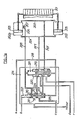
- FIGS. 1 and 1a respectively represent, on the one hand, a regulator as described in the document FR-A-2406079 recalled above and the device for regulating the nozzle section combined with this regulator, according to an embodiment of the invention; the pipes shown in these figures are connected to the points which are marked a, b, c, d and e.
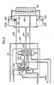
- FIG. 2 is a view similar to FIG. 1a, the members being in the position they occupy when the emergency regulator is in service, the combustion chambers of the turbojet engine being ignited.
- FIGS. 3 and 4 are detailed views of the piston of the pilot cylinder and of the regulation orifices which it controls.
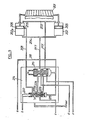
- FIG. 5 shows a variant of the device shown in FIGS. 1a and 2.
- Figure 8 schematically shows the device of Figure 7 in another operating position.
- FIG. 7 of the Applicant's French patent 77.30486 publication number 2 406 079 has been reproduced, with a few modifications which will result from the description below, while retaining the reference numbers already used in said FIG. patent, which will facilitate the identification of organs.
- the main regulator with its pump 52 in 65 the fuel flow line to the injectors of the combustion chambers, in 14 the emergency regulator with its pump 1, in 16 the valve with rotary plug 80 whose the pilot controls the rotation by the electric motor 17 when the pilot wants to control the standby flow, at 55 the transformer with mobile drawer 56, which, depending on the position it occupies, routes the fuel discharged by the pump of the main regulator 51 towards the injectors of the combustion chambers, then putting the line 64 intended for the supply of the fuel supplied by the emergency pump 1 back to 102, or vice versa (in the drawing the drawer 56 is shown in the position where the regulator main 51 with its pump 52 is in service).
- valve which can either return the discharge of the emergency pump 1 upstream of the valve 80 (it is the position of the valve valve 7 which is shown in Figure 1), or isolate the return flow so that the high pressure supplied by the emergency pump becomes active.
- a movable slide actuated by the pressure taken by the piping 69 on the discharge of the pump 1 and, in opposition, by the spring 70 and by the pressure taken in the piping 95 downstream of the electromagnetic valve 77. This valve is normally closed. It is opened by the pilot when he wants to put the emergency regulator into service.
- the device for regulating the section of the nozzle connected according to a, b, c will now be described with reference to FIG. 1a.
- the members are also in the position where the regulation is carried out by the main regulator.
- FIG. 1a there is shown schematically in 201 all of the movable flaps used to adjust the useful section of the nozzle of a turbojet.
- the constitution of such a device, capable of numerous variants, is in itself well known and does not need to be described in detail.
- a set of hydraulic cylinders distributed around the axis of the nozzle and each actuating a flap or a group of flaps.
- These various jacks supplied in parallel are of usual construction, as shown for jack 202, with a pipe 203 for the admission of the opening pressure of the nozzle designated hereinafter by POT and a pipe 204 for the admission of the nozzle closing pressure designated by PFT, In this way, a displacement of the piston 205 of the cylinders, from right to left of FIG. 1a, corresponds to the opening of the nozzle, while a displacement of the left to right corresponds to the closure.
- One of the jacks 202p playing the role of pilot jack, is shown in the upper part of FIG. 1a. It is also connected like the others to the pipes 203 and 204, but also comprises in an intermediate zone of its wall, suitably chosen, two holes 206-207, for example staggered on a generator, at an interval adapted to the thickness of the piston, so that in a certain position thereof it simultaneously closes these two holes. These are both connected to a pipe 208 which, by the operation of a drawer 209, can either be closed at 210 (FIG. 1a) therefore put out of action, or connected by 211 (FIG. 2) with the return of the pumps.
- a pipe 208 which, by the operation of a drawer 209, can either be closed at 210 (FIG. 1a) therefore put out of action, or connected by 211 (FIG. 2) with the return of the pumps.
- a kind of switching 214 which has the function of substituting for the pressures supplied by the main regulator 51, for the control of the nozzle cylinders 202 (pressures POT and PFT), those supplied by the emergency regulator 14 when the latter is put into action, and vice versa.
- the electromagnetic valve 77 is closed, so that the chamber 70a is brought to the same pressure as the chamber 68 via the orifice 76.
- the slide 67 occupies the position (shown in FIG. 1) for which it returns the tubing 66 connected at a to 212 the pipe 218.
- the switching device 214 the slide 219 of the transformer 220 is placed, by its spring 221, in the figured position for which the pipes 203 and 204 of the jacks are supplied by the main regulator 51 of which the pressure outputs are connected at points d and e.
- the drawer 209 is put by its spring 222 in the figured position where it closes the tube 208 leading to the holes 206 and 207 of the pilot cylinder 202p. These holes therefore remain out of action and the regulation of the nozzle is carried out according to the laws which are specific to the main regulator.
- the nozzle can be and remain wide open, which corresponds to the position of the pistons 205 shown in FIG. 1a.
- the drawer 219 then cuts the communication of the pipes 203 and 204 with the main regulator and, on the contrary, allows the fuel discharged at c by the emergency pump to pass towards these pipes through the orifices 223 and 224 unmasked by the drawer 209.
- the nozzle is fully open, which corresponds to the position of the pistons 205 of the jacks shown in FIG. La, the fuel arriving through the piping 203 and that filling the right chambers of the jacks can leak through the piping 208 towards the return 211.
- the action of the PFT pressure becomes preponderant compared to the POT pressure and the jacks reduce the section of the nozzle allowing an increase in the thrust.
- the closing movement continues until the piston of the pilot cylinder comes to the right of the holes 206 and 207 by closing them.
- the arrangement of the two successive bores has the advantage of ensuring a precise position of the jack whatever the direction of the forces on the rod.
- the plug 80 is placed in a position such that it feeds the pipe 18 through the lights 82 and the tap 77 is opened with electromagnetic control to produce the opening of the valve 92 sending fuel to the ignition injectors of the chambers. combustion.
- the fuel sent to b maintains the pressure above the drawer 209, so that the pressures above and below this drawer being approximately equal the spring 222 keeps the drawer 209 in the position of FIG. 1a, while the drawer 219 has taken the position of FIG. 2.
- the nozzle is then completely open for re-ignition.
- the through holes 223, 224 of the emergency fuel, controlled by the slide 209, are provided with diaphragms. These diaphragms are useful for adjusting the speed of movement of the flaps of the nozzle during transient movements and their section is adjusted for this purpose.
- the orifices 206 and 207 are completely closed, their interval being for this purpose suitably adapted to the thickness of the piston.
- the pressures POT and PFT are then both equal to the pressure supplied by the emergency pump in c.
- the wall of the pilot cylinder 202p does not includes only a hole 206.
- the transformer 219 is unchanged, as is the piping circuit.
- the slide 209 is modified by the arrangement of an axial channel 209a which, in its emergency operating position shown in FIG. 5, puts back the pressure POT.
- the slide valve 219 of the transformer and the slide valve 209 being in the position shown in FIG. 5, the PFT pressure is connected by c to the discharge pressure of the emergency pump, while the POT pressure is connected to the return by the axial hole 209a of the slide 209.
- the flaps of the nozzle therefore move towards the closure until the piston of the pilot cylinder passes to the right of the hole 206 as shown in FIG. 5.
- the pressure PFT leaks back and the leakage rate, through the diaphragm passage 224, generates a pressure drop which reduces the PFT pressure until the piston of the pilot cylinder and, consequently, the flaps of the nozzle.
- the cylinder of the pilot cylinder 202p does not have a bore on its wall.
- a tube 225 fixed on the bottom of the cylinder, and penetrating into an axial bore 226 of the piston and its rod, the external surface of the tube 225 and the surface of the bore 226 being adapted to each other, for example by running in, so as to minimize fluid leakage between the tube and the bore while allowing movement of the piston relative to the tube without excessive friction.
- the tube 225 is pierced with an orifice 227 which can be closed or uncovered by the piston 205 in the movement of this piston.
- the device can be modified as shown in FIG. 7.
- the tube 225 is not pierced laterally but its freely open end 228 cooperates with a small piston 229, disposed in a bore 226 of the piston rod of the pilot cylinder, a bore which is in communication via a channel 230 with the chamber located to the right of the piston which receives the POT pressure, which thus prevails in the bore 226 to the right of the small auxiliary piston 229.
- the piston 229 can play inside the bore 226 to allow the continuation of the movement of the piston 205 to the left after the end 228 of the tube 225 has come into application on the piston 229. Or when the piston 205 moves to the right for closing the nozzle, the valve formed by the end 228 of the tube 225 and the piston 229 remains closed at the start of this movement, as shown in the diagram in FIG. 8. The piston 229 remains fixed until said piston comes into abutment against the internal shoulder 231 of the main piston 205, moment from which the end 228 of the tube 225 is uncovered allowing the pressure to drop in the left chamber of the jack, as shown in figure 7.
Description
La présente invention concerne un dispositif de commande et de régulation de la section d'ouverture d'une tuyère propulsive.The present invention relates to a device for controlling and regulating the opening section of a propellant nozzle.
On connaît déjà par exemple des turboréacteurs d'aviation équipés d'un régulateur principal qui dans les conditions normales, règle le débit de carburant envoyé aux chambres de combustion, et d'un régulateur auxiliaire ou régulateur de secours que le pilote peut substituer au régulateur principal en cas de panne de celui-ci, pour permettre une continuation du vol jusqu'au terrain le plus proche.Aviation turbojet engines are already known, for example, equipped with a main regulator which under normal conditions regulates the flow of fuel sent to the combustion chambers, and an auxiliary regulator or emergency regulator which the pilot can replace the regulator. main in the event of its failure, to allow a continuation of the flight to the nearest terrain.
Une combinaison de ce genre a déjà été décrite dans la demande de brevet française 77.30486 (numéro de publication 2406 079) déposée par la Demanderesse le 11 octobre 1977.A combination of this kind has already been described in French patent application 77.30486 (publication number 2406 079) filed by the Applicant on October 11, 1977.
Par ailleurs, FR-A 1 514 925 décrit un dispositif de commande d'une tuyère réglable dans lequel en cas de défaillance d'un dispositif primaire, celui-ci est verrouillé dans une position déterminée et une intervention du pilote commande un dispositif secondaire de secours.Furthermore, FR-A 1 514 925 describes a device for controlling an adjustable nozzle in which in the event of a failure of a primary device, the latter is locked in a determined position and an intervention by the pilot controls a secondary device for rescue.
US A-2 834182 décrit un système de commande de tuyère comportant un circuit de secours en cas de panne du circuit électrique principal. Ce circuit de secours, enclenché par le pilote, commande un distributeur d'alimentation du vérin de commande.US A-2 834182 describes a nozzle control system comprising an emergency circuit in the event of failure of the main electrical circuit. This emergency circuit, initiated by the pilot, controls a power distributor for the control jack.
L'invention apporte une solution au problème que peut poser l'obtention automatique d'une poussée de propulsion suffisante quand on passe au vol avec régulateur de secours en service, en évitant toute intervention manuelle directe du pilote au niveau du dispositif de commande de tuyère.The invention provides a solution to the problem which the automatic obtaining of a sufficient propulsion thrust can pose when passing over the flight with an emergency regulator in service, avoiding any direct manual intervention by the pilot at the nozzle control device. .
Cette solution, comportant l'emploi d'une tuyère équipée d'un réglage de section commandé par au moins un vérin hydraulique et permettant de faire varier la poussée par variation de cette section, se caractérise en ce que les organes de commutation de la marche normale en marche secours comportent un tiroir ou organe équivalent qui coopère avec un conduit relié à au moins un orifice que comporte le vérin, ou l'un d'eux quand il y en a plusieurs, en plus de ses tuyauteries d'alimentation fournissant les pressions d'ouverture et de fermeture de la tuyère, de manière que selon la position du piston de vérin, l'orifice est tantôt obturé, tantôt découvert, établissant la communication avec l'une ou l'autre des chambres du vérin pendant que le tiroir obture ledit conduit pendant la marche normale et le met au contraire à l'échappement vers le retour de la pompe du système d'alimentation lors de la marche en secours, de telle sorte que la pression différentielle engendrée dans le vérin hydraulique commande la tuyère en secours, la section de la tuyère prenant une valeur intermédiaire qui assure automatiquement au moteur une poussée suffisante tout en évitant le risque de pompage de compresseur. Une autre caractéristique de l'invention consiste en ce que le tiroir peut recevoir, par une manoeuvre du pilote au début de la commutation susdite, une commande momentanée le maintenant dans sa position de marche normale, de sorte que le vérin se met ou reste alors dans la position correspondant à la pleine ouverture de la tuyère afin de faciliter un rallumage des chambres de combustion si c'est nécessaire.This solution, comprising the use of a nozzle equipped with a section adjustment controlled by at least one hydraulic cylinder and making it possible to vary the thrust by variation of this section, is characterized in that the gear switching members normal in emergency operation include a drawer or equivalent member which cooperates with a conduit connected to at least one orifice that comprises the jack, or one of them when there are several, in addition to its supply pipes supplying the opening and closing pressures of the nozzle, so that, depending on the position of the cylinder piston, the orifice is sometimes closed, sometimes uncovered, establishing communication with one or other of the chambers of the cylinder while the drawer closes said conduit during normal operation and instead puts it in the exhaust towards the return of the pump of the supply system during emergency operation, so that the differential pressure generated in the hydraulic cylinder lique controls the back-up nozzle, the section of the nozzle taking an intermediate value which automatically provides the engine with sufficient thrust while avoiding the risk of compressor pumping. Another characteristic of the invention consists in that the drawer can receive, by a maneuver of the pilot at the start of the above-mentioned switching, a momentary command keeping it in its normal operating position, so that the actuator is then put or remains in the position corresponding to the full opening of the nozzle to facilitate re-ignition of the combustion chambers if necessary.
Le fluide hydraulique utilisé pour la commande des vérins est, de préférence, le carburant lui- même, sous la pression fournie par la pompe du régulateur principal pendant la marche normale ou sous la pression fournie par la pompe du régulateur de secours, lors de la marche en secours.The hydraulic fluid used to control the cylinders is preferably the fuel itself, under the pressure supplied by the pump of the main regulator during normal operation or under the pressure supplied by the pump of the emergency regulator, when rescue.
La description qui va suivre en regard des dessins annexés donnés à titre d'exemples non limitatifs, fera bien comprendre comment l'invention peut être réalisée, les particularités qui ressortent tant du texte que des dessins faisant, bien entendu, partie de ladite invention.The description which follows with reference to the appended drawings given by way of nonlimiting examples will make it clear how the invention can be implemented, the features which emerge both from the text and from the drawings which, of course, form part of said invention.
Les figures 1 et 1a représentent respectivement, d'une part, un régulateur tel que décrit dans le document FR-A-2406079 rappelé ci-dessus et le dispositif de régulation de la section de tuyère combiné avec ce régulateur, selon un mode de réalisation de l'invention; les tuyauteries représentées sur ces figures se raccordent aux points qui sont marqués a, b, c, d et e.FIGS. 1 and 1a respectively represent, on the one hand, a regulator as described in the document FR-A-2406079 recalled above and the device for regulating the nozzle section combined with this regulator, according to an embodiment of the invention; the pipes shown in these figures are connected to the points which are marked a, b, c, d and e.
De plus, sur les figures, les organes sont représentés dans la position qu'ils occupent quand le régulateur principal est en service.In addition, in the figures, the members are shown in the position they occupy when the main regulator is in service.
La figure 2 est une vue semblable à la figure 1a, les organes étant dans la position qu'ils occupent quand le régulateur de secours est en service, les chambres de combustion du turboréacteur étant allumées.FIG. 2 is a view similar to FIG. 1a, the members being in the position they occupy when the emergency regulator is in service, the combustion chambers of the turbojet engine being ignited.
Les figures 3 et 4 sont des vues de détail du piston du vérin-pilote et des orifices de régulation qu'il contrôle.FIGS. 3 and 4 are detailed views of the piston of the pilot cylinder and of the regulation orifices which it controls.
La figure 5 montre une variante du dispositif représenté sur les figures la et 2.FIG. 5 shows a variant of the device shown in FIGS. 1a and 2.
Les figures 6 et 7 représentent deux autres variantes.Figures 6 and 7 show two other variants.
La figure 8 montre schématiquement le dispositif de la figure 7 dans une autre position de fonctionnement.Figure 8 schematically shows the device of Figure 7 in another operating position.
Sur la figure 1, on a reproduit, avec quelques modifications qui résulteront de la description ci-après, la figure 7 du brevet français de la Demanderesse 77.30486 (numéro de publication 2 406 079), en conservant les numéros de référence déjà utilisés dans ledit brevet, ce qui facilitera l'identification des organes.In FIG. 1, FIG. 7 of the Applicant's French patent 77.30486 (publication number 2 406 079) has been reproduced, with a few modifications which will result from the description below, while retaining the reference numbers already used in said FIG. patent, which will facilitate the identification of organs.
Les trois branchements marqués a, b, c, qui ont été ajoutés à la figure 7 du brevet susdit, se raccordent à ceux marqués des mêmes références sur la figure 1a ou, l'on a représenté un dispositif de contrôle de la section de sortie de la tuyère, selon une forme de réalisation de l'objet de l'invention.The three connections marked a, b, c, which have been added to FIG. 7 of the aforementioned patent, are connected to those marked with the same references in FIG. 1a or, a device for controlling the outlet section has been represented. of the nozzle, according to one embodiment of the object of the invention.
On ne décrira pas en détail les organes du régulateur de secours représenté figure 1 et l'on pourra se référer à la description qui en a été donnée dans le brevet susdit.We will not describe in detail the bodies of the emergency regulator shown in Figure 1 and we may refer to the description which was given in the above patent.
Brièvement, on voit en 51 le régulateur principal avec sa pompe 52, en 65 le conduit de départ du carburant vers les injecteurs des chambres de combustion, en 14 le régulateur de secours avec sa pompe 1, en 16 le robinet avec boisseau tournant 80 dont le pilote commande la rotation par le moteur électrique 17 quand le pilote veut piloter le débit en secours, en 55 le transiteur avec tiroir mobile 56, lequel, selon la position qu'il occupe, achemine le carburant refoulé par la pompe du régulateur principal 51 vers les injecteurs des chambres de combustion, en mettant alors au retour par 102 le conduit 64 destiné à l'amenée du carburant fourni par la pompe de secours 1, ou réciproquement (sur le dessin le tiroir 56 est représenté dans la position où le régulateur principal 51 avec sa pompe 52 est en service). On voit encore en 7 une soupape qui peut soit mettre au retour le refoulement de la pompe de secours 1 en amont du boisseau 80 (c'est la position du tiroir de la soupape 7 qui est représentée sur la figure 1), soit isoler le refoulement du retour pour que la haute pression fournie par la pompe de secours devienne active. On voit aussi en 67 un tiroir mobile actionné par la pression prise par la tuyauterie 69 sur le refoulement de la pompe 1 et, en opposition, par le ressort 70 et par la pression prise dans la tuyauterie 95 en aval du robinet électromagnétique 77. Ce robinet est normalement fermé. Il est ouvert par le pilote quand celui-ci veut mettre en service le régulateur de secours.Briefly, we see in 51 the main regulator with its
Le dispositif de régulation de la section de la tuyère raccordé selon a, b, c va maintenant être décrit en regard de la figure 1a. Sur cette figure, les organes sont également dans la position où la régulation est effectuée par le régulateur principal.The device for regulating the section of the nozzle connected according to a, b, c will now be described with reference to FIG. 1a. In this figure, the members are also in the position where the regulation is carried out by the main regulator.
Sur la figure 1 a, on a représenté schématiquement en 201 l'ensemble des volets mobiles servant à régler la section utile de la tuyère d'un turboréacteur. La constitution d'un tel dispositif, susceptible d'ailleurs de nombreuses variantes, est en elle-même bien connue et n'a pas besoin d'être décrite en détail.In Figure 1a, there is shown schematically in 201 all of the movable flaps used to adjust the useful section of the nozzle of a turbojet. The constitution of such a device, capable of numerous variants, is in itself well known and does not need to be described in detail.
Le mouvement de ces volets pour augmenter ou réduire la section utile de la tuyère est commandé par un ensemble de vérins hydrauliques répartis autour de l'axe de la tuyère et actionnant chacun un volet ou un groupe de volets. Ces divers vérins alimentés en parallèle sont de constitution habituelle, comme représenté pour le vérin 202, avec une tubulure 203 pour l'admission de la pression d'ouverture de la tuyère désignée ci-après par POT et une tubulure 204 pour l'admission de la pression de fermeture de la tuyère désignée par PFT, De la sorte, un déplacement du piston 205 des vérins, de la droite vers la gauche de la figure 1a, correspond à l'ouverture de la tuyère, tandis qu'un déplacement de la gauche vers la droite correspond à la fermeture.The movement of these flaps to increase or reduce the useful section of the nozzle is controlled by a set of hydraulic cylinders distributed around the axis of the nozzle and each actuating a flap or a group of flaps. These various jacks supplied in parallel are of usual construction, as shown for
L'un des vérins 202p, jouant le rôle de vérin-pilote, est représenté à la partie supérieure de la figure 1a. Il est également raccordé comme les autres aux tubulures 203 et 204, mais comporte en outre dans une zone intermédiaire de sa paroi, convenablement choisie, deux perçages 206-207, par exemple échelonnés sur une génératrice, à un intervalle adapté à l'épaisseur du piston, de manière que dans une certaine position de celui-ci il obture simultanément ces deux perçages. Ceux-ci sont reliés l'un et l'autre à une tubulure 208 qui, par le fonctionnement d'un tiroir 209, peut être soit obturée en 210 (figure la) donc mise hors d'action, soit reliée par 211 (figure 2) avec le retour des pompes.One of the
Entre le régulateur principal 51 et le régulateur de secours 14 est disposée une sorte de commutation 214 qui a pour fonction de substituer aux pressions fournies par le régulateur principal 51, pour la commande des vérins de tuyère 202 (pressions POT et PFT), celles fournies par le régulateur de secours 14 quand celui-ci est mis en action, et réciproquement.Between the
Dans la position des organes représentés sur les figures 1 et 1a, le régulateur de secours n'étant pas en action et seul étant en action le régulateur principal 51, le robinet électromagnétique 77 est fermé, de sorte que la chambre 70a est mise à la même pression que la chambre 68 par l'intermédiaire de l'orifice 76. Sous l'action du ressort 70, le tiroir 67 occupe la position (représentée figure 1) pour laquelle il met au retour en 212 la tubulure 66 reliée en a à la tubulure 218. De la sorte, dans le dispositif de commutation 214, le tiroir 219 du transiteur 220 est placé, par son ressort 221, dans la position figurée pour laquelle les tubulures 203 et 204 des vérins sont alimentées par le régulateur principal 51 dont les sorties de pression sont raccordées aux points d et e. De plus, le tiroir 209 est mis par son ressort 222 dans la position figurée où il obture la tubulure 208 aboutissant aux perçages 206 et 207 du vérin-pilote 202p. Ces perçages restent donc hors d'action et la régulation de la tuyère s'effectue selon les lois qui sont propres au régulateur principal.In the position of the members represented in FIGS. 1 and 1a, the emergency regulator not being in action and only being in action the
En particulier, la tuyère peut être et rester ouverte en grand, ce qui correspond à la position des pistons 205 représentée sur la figure 1a.In particular, the nozzle can be and remain wide open, which corresponds to the position of the
Si maintenant en cas de panne du régulateur principal 51, on met en service le régulateur de secours 14 en agissant sur le robinet électromagnétique 77, le boisseau 80 étant placé de façon qu'il n'alimente pas la conduite 18 par les lumières 82 (figure 1) comme décrit dans le brevet susdit, il en résulte deux choses:
- - tout d'abord la pression dans la chambre 70a est mise au retour pompe par l'intermédiaire du robinet électromagnétique 77, la pression de la
tubulure 69 étant maintenue à la haute pression pousse letiroir 67 dans la position opposée à celle que représente la figure 1 et lestubulures 66 et 218 sont isolées duretour 212. - - par le
clapet surpresseur 30 qui reçoit le carburant refoulé par la pompe de secours, la haute pression de cette pompe est admise dans lestubulures 66 et 218, ce qui détermine, d'une part, le déplacement dutransiteur 55 vers la droite et l'envoi du carburant de secours vers les chambres de combustion et, d'autre part, le déplacement destiroirs 209 et 219 dans la position que représente la figure 2.
- - first of all, the pressure in the chamber 70a is brought to the pump return by means of the
electromagnetic tap 77, the pressure of thetubing 69 being maintained at high pressure pushes theslide 67 into the position opposite to that represented by the Figure 1 and thepipes return 212. - - by the
pressure relief valve 30 which receives the fuel discharged by the emergency pump, the high pressure of this pump is admitted in thepipes transformer 55 to the right and the sending of the emergency fuel to the combustion chambers and, on the other hand, the displacement of thedrawers
Comme on le voit, le tiroir 219 coupe alors la communication des tuyauteries 203 et 204 avec le régulateur principal et permet au contraire au carburant refoulé en c par la pompe de secours de passer vers ces tuyauteries à travers les orifices 223 et 224 démasqués par le tiroir 209.As can be seen, the
En même temps, celui-ci a mis au retour par 211 la tubulure 208 communiquant avec les,perçages latéraux 206 et 207 du vérin-pilote 202p.At the same time, the latter placed the
En supposant que dans cette période où l'on vient de quitter le fonctionnement normal, la tuyère soit pleinement ouverte, ce qui correspond à la position des pistons 205 des vérins représentés sur la figure la, le carburant arrivant par la tuyauterie 203 et celui remplissant les chambres de droite des vérins peut fuir par la tuyauterie 208 vers le retour 211. Autrement dit, l'action de la pression PFT devient prépondérante par rapport à la pression POT et les vérins diminuent la section de la tuyère en permettant une augmentation de la poussée. Le mouvement de fermeture se poursuit jusqu'à ce que le piston du vérin-pilote vienne au droit des perçages 206 et 207 en les obturant. La disposition des deux perçages successifs a l'avantage d'assurer une position précise du vérin quel que soit le sens des efforts sur la tige.Assuming that in this period when we have just left normal operation, the nozzle is fully open, which corresponds to the position of the
Le fonctionnement qui précède suppose qu'il n'y a pas eu extinction des chambres de combustion avant de passer au régime de secours.The above operation assumes that the combustion chambers were not extinguished before switching to the emergency mode.
Si cette extinction a eu lieu, il faut rallumer les chambres de combustion.If this extinction has taken place, the combustion chambers must be relighted.
Pour cela, on place le boisseau 80 dans une position telle qu'il alimente la conduite 18 par les lumières 82 et on ouvre le robinet 77 à commande électromagnétique pour produire l'ouverture du clapet 92 envoyant du carburant aux injecteurs d'allumage des chambres de combustion. En même temps, le carburant envoyé en b maintient la pression au-dessus du tiroir 209, de sorte que les pressions au-dessus et au-dessous de ce tiroir étant à peu près égales le ressort 222 maintient le tiroir 209 dans la position de la figure 1a, tandis que le tiroir 219 a pris la position de la figure 2.For this, the plug 80 is placed in a position such that it feeds the
Dans cette configuration des tiroirs, les vérins 202 sont alimentés de la manière suivante:
- - la pression PFT est mise au retour en 211
par le tiroir 209. - - la pression POT est égale à la haute pression de la pompe de secours transmise en c.
- - the PFT pressure is returned to 211 by the
drawer 209. - - the POT pressure is equal to the high pressure of the emergency pump transmitted in c.
La tuyère est alors complètement ouverte pour le rallumage.The nozzle is then completely open for re-ignition.
Quand le rallumage a été effectué, le pilote fait tourner le boisseau 80 qui quitte la position de rallumage. Entre temps, l'ouverture du clapet 91 pour l'envoi du carburant aux injecteurs d'allumage a fait chuter la pression dans la tuyauterie 18 et par conséquent par b sur la face supérieure du tiroir 209. Ce tiroir qui reste soumis sur sa face inférieure à la pression du fluide qui lui est envoyé par le clapet 30 et par a est déplacé à l'encontre du ressort 222 pour prendre la position représentée sur la figure 2 et l'on revient au mode de réglage précédemment décrit.When the re-ignition has been carried out, the pilot turns the plug 80 which leaves the re-ignition position. Meanwhile, the opening of the
On voit sur la figure 2 que les orifices de passage 223, 224 du carburant secours, contrôlés par le tiroir 209, sont munis de diaphragmes. Ces diaphragmes sont utiles pour régler la vitesse de déplacement des volets de la tuyère durant les mouvements transitoires et leur section est ajustée à cet effet.It can be seen in FIG. 2 that the through
Ainsi, dans le réglage précédemment décrit, quand la tuyère se déplace vers sa position de fermeture et que le piston du vérin-pilote 202p commence à obturer les orifices 206 et 207 le vérin-pilote réalise avec le diaphragme 223 une sorte de potentiomètre hydraulique. De la sorte, au fur et à mesure du mouvement des volets de tuyère vers la fermeture, la pression POT augmente rapidement jusqu'à l'obtention de l'équilibre des vérins. La position de stabilisation dépend des efforts à fournir par les vérins, lesquels varient avec les conditions de fonctionnement du turboréacteur.Thus, in the previously described setting, when the nozzle moves to its closed position and the piston of the
A un certain moment, les orifices 206 et 207 sont complètement obturés, leur intervalle étant à cet effet convenablement adapté à l'épaisseur du piston. Les pressions POT et PFT sont alors l'une et l'autre égales à la pression fournie par la pompe de secours en c.At a certain moment, the
L'effort sur chaque vérin se réduit à l'effet de la différence des surfaces actives des faces opposées des pistons, en raison de la section de leur tige. Cet effort peut être encore trop élevé dans certains conditions et conduire la tuyère à continuer son mouvement vers la fermeture, cela jusqu'au moment où les orifices 206 se trouvent découverts. Le débit de fuite provoqué ainsi à travers le passage à diaphragme 224 y engendre une perte de charge qui fait chuter la pression PFT en conduisant à la stabilisation de la tuyère. Suivant les conditions de fonctionnement du réacteur, le dispositif décrit conduit donc à une régulation de la tuyère dans une position qui n'est pas rigoureusement définie et qui peut varier entre les deux extrêmes schématisés par les figures 3 et 4.The force on each cylinder is reduced to the effect of the difference in the active surfaces of the opposite faces of the pistons, due to the cross section of their rod. This effort may still be too high under certain conditions and lead the nozzle to continue its movement towards closing, this until the
Ceci suppose naturellement que la pression fournie en c par la pompe de secours soit suffisante pour que le cas de la figure 3 soit permis, ce qui sera généralement réalisé dans la plus grande partie du domaine de vol secours. Dans le cas contraire, la tuyère s'ouvrirait partiellement jusqu'à ce que l'effort à fournir, qui diminue quand la section de la tuyère augmente, corresponde au niveau de pression disponible en c.This naturally presupposes that the pressure supplied at c by the emergency pump is sufficient for the case of FIG. 3 to be allowed, which will generally be achieved in most of the emergency flight domain. Otherwise, the nozzle would partially open until the force to be supplied, which decreases when the section of the nozzle increases, corresponds to the level of pressure available in c.
Dans la variante de réalisation que représente la figure 5, la paroi du vérin-pilote 202p ne comporte qu'un perçage 206.In the alternative embodiment shown in FIG. 5, the wall of the
Le transiteur 219 est inchangé de même que le circuit des tuyauteries.The
Le tiroir 209 est modifié par l'aménagement d'un canal axial 209a qui, dans sa position de marche en secours représentée sur la figure 5, met au retour la pression POT.The
Le fonctionnement en marche normale, c'est-à-dire avec le régulateur principal, reste inchangé par rapport à celui qui a été décrit ci-dessus, en regard des figures 1 et la.The operation in normal operation, that is to say with the main regulator, remains unchanged with respect to that which has been described above, with reference to FIGS. 1 and 1a.
Dans le fonctionnement secours, le tiroir 219 du transiteur et le tiroir 209 étant dans la position représentée figure 5, la pression PFT est reliée par c à la pression de refoulement de la pompe de secours, tandis que la pression POT est reliée au retour par le perçage axial 209a du tiroir 209. Les volets de la tuyère se déplacent donc vers la fermeture jusqu'au moment où le piston du vérin-pilote passe à la droite du perçage 206 comme représenté sur la figure 5. A ce moment, la pression PFT fuit vers le retour et le débit de fuite, à travers le passage à diaphragme 224, engendre une perte de charge qui fait diminuer la pression PFT jusqu'à la stabilisation du piston du vérin-pilote et, par conséquent, des volets de la tuyère. Quand l'orifice 206 est complètement découvert, la pression PFT devient pratiquement égale à la pression au retour de la pompe de secours et l'effort sur chaque vérin se réduit à l'effet de la section différentielle due à la tige du piston, sous l'effet de la pression de retour qui règne de chaque côté du piston,In emergency operation, the
Dans le mode de réalisation représenté sur la figure 6, le cylindre du vérin-pilote 202p ne présente pas de perçage sur sa paroi. Dans l'axe du cylindre, est disposé un tube 225, fixé sur le fond du cylindre, et pénétrant dans un alésage axial 226 du piston et de sa tige, la surface externe du tube 225 et la surface de l'alésage 226 étant adaptées l'une à l'autre, par exemple par rodage, de manière à réduire au minimum les fuites de fluide entre le tube et l'alésage tout en permettant un mouvement du piston par-rapport au tube sans frottement excessif. En un point convenable de sa paroi, le tube 225 est percé d'un orifice 227 qui peut être obturé ou découvert par le piston 205 dans le mouvement de ce piston.In the embodiment shown in Figure 6, the cylinder of the
Comme on le comprend, si on relie les orifices d'extrémité du cylindre aux pressions POT, PFT, selon un schéma semblable à celui de la figure 5, et l'intérieur du tube 225 à la conduite 208 à travers le fond du cylindre, le dispositif fonctionnera de façon tout à fait semblable à ce qui a été décrit en regard de la figure 5.As will be understood, if the end ports of the cylinder are connected to the pressures POT, PFT, according to a diagram similar to that of FIG. 5, and the interior of the
Si l'on veut éviter l'inconvénient qui peut résulter de la nécessité d'effectuer un bon centrage entre le tube 225 et le corps du vérin-pilote, on peut modifier le dispositif comme représenté sur la figure 7.If we want to avoid the inconvenience that may result from the need to perform good centering between the
Dans cette variante, le tube 225 n'est pas percé latéralement mais son extrémité librement ouverte 228 coopère avec un petit piston 229, disposé dans un alésage 226 de la tige du piston du vérin-pilote, alésage qui est en communication par un canal 230 avec la chambre située à la droite du piston qui reçoit la pression POT, laquelle règne ainsi dans l'alésage 226 à la droite du petit piston auxiliaire 229.In this variant, the
Le fonctionnement de cette variante se comprend aisément.The operation of this variant is easily understood.
Quand le piston du vérin-pilote se trouve vers la gauche de la figure 7, c'est-à-dire en position "tuyère ouverte", l'extrémité libre du tube 225 s'appuie contre le piston auxiliaire 229. L'extrémité 228 du tube 225 et la face coopérante du piston auxiliaire 229 étant dressées bien planes, le tube 225 et le piston 229 constituent ensemble un clapet qui est fermé.When the piston of the pilot cylinder is to the left of FIG. 7, that is to say in the "open nozzle" position, the free end of the
Le piston 229 peut jouer à l'intérieur de l'alésage 226 pour permettre la continuation du mouvement du piston 205 vers la gauche après que l'extrémité 228 du tube 225 soit venue en application sur le piston 229. Ouand le piston 205 se déplace vers la droite pour la fermeture de la tuyère, le clapet formé par l'extrémité 228 du tube 225 et le piston 229 reste fermé au début de ce mouvement, comme le montre le schéma de la figure 8. Le piston 229 reste fixe jusqu'à ce que ledit piston vienne en butée contre l'épaulement interne 231 du piston principal 205, moment à partir duquel l'extrémité 228 du tube 225 se trouve découverte en permettant la chute de la pression dans la chambre de gauche du vérin, comme représenté dans la figure 7.The
Claims (6)
Applications Claiming Priority (2)
| Application Number | Priority Date | Filing Date | Title |
|---|---|---|---|
| FR8219949 | 1982-11-29 | ||
| FR8219949A FR2536793A1 (en) | 1982-11-29 | 1982-11-29 | DEVICE FOR CONTROLLING AND REGULATING THE OPENING SECTION OF A PROPULSIVE TUBE |
Publications (2)
| Publication Number | Publication Date |
|---|---|
| EP0112198A1 EP0112198A1 (en) | 1984-06-27 |
| EP0112198B1 true EP0112198B1 (en) | 1986-09-03 |
Family
ID=9279601
Family Applications (1)
| Application Number | Title | Priority Date | Filing Date |
|---|---|---|---|
| EP83402152A Expired EP0112198B1 (en) | 1982-11-29 | 1983-11-07 | Control and regulation apparatus for the opening section of a propulsive nozzle |
Country Status (4)
| Country | Link |
|---|---|
| US (1) | US4501117A (en) |
| EP (1) | EP0112198B1 (en) |
| DE (1) | DE3365895D1 (en) |
| FR (1) | FR2536793A1 (en) |
Families Citing this family (1)
| Publication number | Priority date | Publication date | Assignee | Title |
|---|---|---|---|---|
| RU2634506C1 (en) * | 2016-12-15 | 2017-10-31 | Публичное Акционерное Общество "Уфимское Моторостроительное Производственное Объединение" (Пао "Умпо") | Control method of aircraft jet turbine engine |
Citations (1)
| Publication number | Priority date | Publication date | Assignee | Title |
|---|---|---|---|---|
| FR2406079A1 (en) * | 1977-10-11 | 1979-05-11 | Snecma | GAS TURBINE REGULATION DEVICE |
Family Cites Families (8)
| Publication number | Priority date | Publication date | Assignee | Title |
|---|---|---|---|---|
| US2726507A (en) * | 1952-01-14 | 1955-12-13 | Solar Aircraft Co | Jet power plant controls |
| US2818703A (en) * | 1954-07-01 | 1958-01-07 | Gen Electric | Jet engine fuel, pressure ratio, and nozzle area control |
| US2834182A (en) * | 1955-06-21 | 1958-05-13 | Charles H Culbertson | High altitude compensation of two position exhaust nozzle control |
| FR1295470A (en) * | 1961-04-25 | 1962-06-08 | Methods and devices for manufacturing solid propellant blocks, in particular for rockets | |
| DE1287862B (en) * | 1963-09-26 | 1969-01-23 | ||
| FR1395470A (en) * | 1964-05-25 | 1965-04-09 | Dowty Fuel Syst Ltd | Aircraft gas turbine control system |
| US4137707A (en) * | 1977-07-22 | 1979-02-06 | General Electric Company | Integrated control system for a gas turbine engine |
| US4142364A (en) * | 1977-07-22 | 1979-03-06 | General Electric Company | Back-up control for gas turbine engine |
-
1982
- 1982-11-29 FR FR8219949A patent/FR2536793A1/en active Granted
-
1983
- 1983-11-07 DE DE8383402152T patent/DE3365895D1/en not_active Expired
- 1983-11-07 EP EP83402152A patent/EP0112198B1/en not_active Expired
- 1983-11-16 US US06/552,383 patent/US4501117A/en not_active Expired - Lifetime
Patent Citations (1)
| Publication number | Priority date | Publication date | Assignee | Title |
|---|---|---|---|---|
| FR2406079A1 (en) * | 1977-10-11 | 1979-05-11 | Snecma | GAS TURBINE REGULATION DEVICE |
Also Published As
| Publication number | Publication date |
|---|---|
| EP0112198A1 (en) | 1984-06-27 |
| FR2536793B1 (en) | 1985-03-08 |
| FR2536793A1 (en) | 1984-06-01 |
| US4501117A (en) | 1985-02-26 |
| DE3365895D1 (en) | 1986-10-09 |
Similar Documents
| Publication | Publication Date | Title |
|---|---|---|
| CA2813923C (en) | Lubricating device having a bypass valve | |
| FR2637942A1 (en) | FUEL DELIVERY VALVE, IN PARTICULAR FOR A TURBOMOTEUR, AND METHOD FOR OPERATING SUCH A TURBOMOTEUR | |
| CA2619352C (en) | Fuel injector device for a turbine engine | |
| FR2467752A1 (en) | HYDRAULIC BRAKE SYSTEM | |
| EP0689006B1 (en) | Method and device for supplying fuel and for cooling the take-off injector in a combustion chamber with two burner heads | |
| FR2692658A1 (en) | Device for controlling at least one directing device, controlling the passage of combustion air, of a burner for gas turbine engine mechanisms. | |
| EP0031770A1 (en) | Supercharged internal-combustion engine, particularly Diesel engine | |
| EP0227495B1 (en) | Steering device for a guided missile by means of lateral nozzles | |
| FR3079879A1 (en) | DISCHARGE VALVE WITH REGULATED OPENING | |
| EP0112198B1 (en) | Control and regulation apparatus for the opening section of a propulsive nozzle | |
| EP0591018A1 (en) | Arc plasma torch and method of application | |
| FR2672944A1 (en) | PROPORTIONAL DISTRIBUTOR AND CONTROL ARRANGEMENT OF A PLURALITY OF HYDRAULIC RECEIVERS COMPRISING FOR EACH RECEIVER SUCH A DISTRIBUTOR. | |
| FR2618528A1 (en) | IMPROVEMENTS IN AUXILIARY COMBUSTION CHAMBERS, FOR SUPERCHARGED INTERNAL COMBUSTION ENGINES, AND INTERNAL COMBUSTION ENGINES EQUIPPED WITH SUCH A CHAMBER | |
| EP0278814B1 (en) | Fuel dose regulating device for turbo machines | |
| EP0582497B1 (en) | Control system for a plurality of hydraulic actuators | |
| FR2890691A1 (en) | "FUEL FLOW CONTROL SYSTEM FOR GAS TURBINE ENGINE HEATING APPARATUS" | |
| FR2711433A1 (en) | Coaxial flow rate regulator | |
| FR2985284A1 (en) | Device for controlling pitch of blades of non-ducted propeller of turbojet of aircraft, has flow reduction unit to limit flow of fluid leaving chambers under effect of displacement of piston in event of interruption of supply of fluid | |
| FR2718190A1 (en) | Fuel injection control valve for a turbomachine. | |
| FR2468775A1 (en) | HYDRAULIC DISTRIBUTOR | |
| EP0434531B1 (en) | Device for initiating auto-reverse movement of a double acting hydraulic cylinder | |
| EP0635679B1 (en) | Injection and control device for atmospheric gas burners of heating appliances, in particular the infrared type | |
| FR3079875A1 (en) | TURBOMACHINE DISCHARGE DEVICE COMPRISING A VALVE | |
| FR2740106A1 (en) | DEVICE FOR CONTROLLING SPACEWISE ENGINE BY VANTING GAS BY MOBILE TUYERE | |
| FR2482670A1 (en) | FUEL INJECTOR |
Legal Events
| Date | Code | Title | Description |
|---|---|---|---|
| PUAI | Public reference made under article 153(3) epc to a published international application that has entered the european phase |
Free format text: ORIGINAL CODE: 0009012 |
|
| 17P | Request for examination filed |
Effective date: 19831117 |
|
| AK | Designated contracting states |
Designated state(s): DE FR GB IT SE |
|
| ITF | It: translation for a ep patent filed |
Owner name: BARZANO' E ZANARDO MILANO S.P.A. |
|
| GRAA | (expected) grant |
Free format text: ORIGINAL CODE: 0009210 |
|
| AK | Designated contracting states |
Kind code of ref document: B1 Designated state(s): DE FR GB IT SE |
|
| REF | Corresponds to: |
Ref document number: 3365895 Country of ref document: DE Date of ref document: 19861009 |
|
| PLBE | No opposition filed within time limit |
Free format text: ORIGINAL CODE: 0009261 |
|
| STAA | Information on the status of an ep patent application or granted ep patent |
Free format text: STATUS: NO OPPOSITION FILED WITHIN TIME LIMIT |
|
| 26N | No opposition filed | ||
| REG | Reference to a national code |
Ref country code: FR Ref legal event code: CL |
|
| ITTA | It: last paid annual fee | ||
| EAL | Se: european patent in force in sweden |
Ref document number: 83402152.9 |
|
| PGFP | Annual fee paid to national office [announced via postgrant information from national office to epo] |
Ref country code: SE Payment date: 20011008 Year of fee payment: 19 |
|
| PGFP | Annual fee paid to national office [announced via postgrant information from national office to epo] |
Ref country code: FR Payment date: 20011023 Year of fee payment: 19 |
|
| PGFP | Annual fee paid to national office [announced via postgrant information from national office to epo] |
Ref country code: GB Payment date: 20011107 Year of fee payment: 19 |
|
| PGFP | Annual fee paid to national office [announced via postgrant information from national office to epo] |
Ref country code: DE Payment date: 20011129 Year of fee payment: 19 |
|
| REG | Reference to a national code |
Ref country code: GB Ref legal event code: IF02 |
|
| REG | Reference to a national code |
Ref country code: FR Ref legal event code: TP Ref country code: FR Ref legal event code: CD |
|
| PG25 | Lapsed in a contracting state [announced via postgrant information from national office to epo] |
Ref country code: GB Free format text: LAPSE BECAUSE OF NON-PAYMENT OF DUE FEES Effective date: 20021107 |
|
| PG25 | Lapsed in a contracting state [announced via postgrant information from national office to epo] |
Ref country code: SE Free format text: LAPSE BECAUSE OF NON-PAYMENT OF DUE FEES Effective date: 20021108 |
|
| PG25 | Lapsed in a contracting state [announced via postgrant information from national office to epo] |
Ref country code: DE Free format text: LAPSE BECAUSE OF NON-PAYMENT OF DUE FEES Effective date: 20030603 |
|
| GBPC | Gb: european patent ceased through non-payment of renewal fee | ||
| EUG | Se: european patent has lapsed | ||
| PG25 | Lapsed in a contracting state [announced via postgrant information from national office to epo] |
Ref country code: FR Free format text: LAPSE BECAUSE OF NON-PAYMENT OF DUE FEES Effective date: 20030731 |
|
| REG | Reference to a national code |
Ref country code: FR Ref legal event code: ST |