EP0112163B1 - Fibre optic cable arrangements - Google Patents
Fibre optic cable arrangements Download PDFInfo
- Publication number
- EP0112163B1 EP0112163B1 EP83307592A EP83307592A EP0112163B1 EP 0112163 B1 EP0112163 B1 EP 0112163B1 EP 83307592 A EP83307592 A EP 83307592A EP 83307592 A EP83307592 A EP 83307592A EP 0112163 B1 EP0112163 B1 EP 0112163B1
- Authority
- EP
- European Patent Office
- Prior art keywords
- cable
- fibre optic
- conductor
- optic cable
- housing
- Prior art date
- Legal status (The legal status is an assumption and is not a legal conclusion. Google has not performed a legal analysis and makes no representation as to the accuracy of the status listed.)
- Expired - Lifetime
Links
- 239000000835 fiber Substances 0.000 title claims abstract description 102
- 230000005684 electric field Effects 0.000 claims abstract description 11
- 239000004020 conductor Substances 0.000 claims description 107
- 239000000463 material Substances 0.000 claims description 19
- 239000000945 filler Substances 0.000 claims description 10
- 230000001681 protective effect Effects 0.000 claims description 9
- 238000005728 strengthening Methods 0.000 claims description 5
- 230000005540 biological transmission Effects 0.000 claims description 4
- 230000015572 biosynthetic process Effects 0.000 claims description 3
- 230000000694 effects Effects 0.000 description 12
- 239000002184 metal Substances 0.000 description 9
- 238000010276 construction Methods 0.000 description 8
- 239000012212 insulator Substances 0.000 description 8
- 230000003287 optical effect Effects 0.000 description 8
- XLYOFNOQVPJJNP-UHFFFAOYSA-N water Substances O XLYOFNOQVPJJNP-UHFFFAOYSA-N 0.000 description 6
- 230000002411 adverse Effects 0.000 description 5
- 239000003921 oil Substances 0.000 description 4
- 230000001627 detrimental effect Effects 0.000 description 3
- 238000004519 manufacturing process Methods 0.000 description 3
- 239000013521 mastic Substances 0.000 description 3
- 239000013307 optical fiber Substances 0.000 description 3
- 230000007704 transition Effects 0.000 description 3
- 229910001369 Brass Inorganic materials 0.000 description 2
- 238000013459 approach Methods 0.000 description 2
- 230000000712 assembly Effects 0.000 description 2
- 238000000429 assembly Methods 0.000 description 2
- 230000000903 blocking effect Effects 0.000 description 2
- 239000010951 brass Substances 0.000 description 2
- 239000011248 coating agent Substances 0.000 description 2
- 238000000576 coating method Methods 0.000 description 2
- 230000008021 deposition Effects 0.000 description 2
- 238000009826 distribution Methods 0.000 description 2
- 230000007613 environmental effect Effects 0.000 description 2
- 239000003344 environmental pollutant Substances 0.000 description 2
- 230000003628 erosive effect Effects 0.000 description 2
- 238000009434 installation Methods 0.000 description 2
- 230000007774 longterm Effects 0.000 description 2
- 231100000719 pollutant Toxicity 0.000 description 2
- 229910052573 porcelain Inorganic materials 0.000 description 2
- 239000000565 sealant Substances 0.000 description 2
- 238000007789 sealing Methods 0.000 description 2
- 229920000181 Ethylene propylene rubber Polymers 0.000 description 1
- 239000004831 Hot glue Substances 0.000 description 1
- 239000000853 adhesive Substances 0.000 description 1
- 230000001070 adhesive effect Effects 0.000 description 1
- 230000008901 benefit Effects 0.000 description 1
- 125000000484 butyl group Chemical group [H]C([*])([H])C([H])([H])C([H])([H])C([H])([H])[H] 0.000 description 1
- 229920005549 butyl rubber Polymers 0.000 description 1
- 238000004891 communication Methods 0.000 description 1
- 150000001875 compounds Chemical class 0.000 description 1
- 229920001940 conductive polymer Polymers 0.000 description 1
- 238000011109 contamination Methods 0.000 description 1
- 230000008878 coupling Effects 0.000 description 1
- 238000010168 coupling process Methods 0.000 description 1
- 238000005859 coupling reaction Methods 0.000 description 1
- 238000001514 detection method Methods 0.000 description 1
- 238000011161 development Methods 0.000 description 1
- 230000018109 developmental process Effects 0.000 description 1
- 239000003989 dielectric material Substances 0.000 description 1
- 230000005611 electricity Effects 0.000 description 1
- 238000002474 experimental method Methods 0.000 description 1
- 239000006260 foam Substances 0.000 description 1
- 239000003365 glass fiber Substances 0.000 description 1
- 238000005470 impregnation Methods 0.000 description 1
- 238000012423 maintenance Methods 0.000 description 1
- 230000013011 mating Effects 0.000 description 1
- 230000007246 mechanism Effects 0.000 description 1
- 239000000203 mixture Substances 0.000 description 1
- 238000012986 modification Methods 0.000 description 1
- 230000004048 modification Effects 0.000 description 1
- 238000012544 monitoring process Methods 0.000 description 1
- 235000019271 petrolatum Nutrition 0.000 description 1
- 229920000642 polymer Polymers 0.000 description 1
- 238000004382 potting Methods 0.000 description 1
- 230000002035 prolonged effect Effects 0.000 description 1
- 230000005855 radiation Effects 0.000 description 1
- 239000011347 resin Substances 0.000 description 1
- 229920005989 resin Polymers 0.000 description 1
- 150000003839 salts Chemical class 0.000 description 1
- 238000007493 shaping process Methods 0.000 description 1
- 229920002379 silicone rubber Polymers 0.000 description 1
- 239000007787 solid Substances 0.000 description 1
- 239000000126 substance Substances 0.000 description 1
- 238000009736 wetting Methods 0.000 description 1
Images


Classifications
-
- G—PHYSICS
- G02—OPTICS
- G02B—OPTICAL ELEMENTS, SYSTEMS OR APPARATUS
- G02B6/00—Light guides; Structural details of arrangements comprising light guides and other optical elements, e.g. couplings
- G02B6/44—Mechanical structures for providing tensile strength and external protection for fibres, e.g. optical transmission cables
- G02B6/4401—Optical cables
- G02B6/4415—Cables for special applications
- G02B6/4416—Heterogeneous cables
- G02B6/4417—High voltage aspects, e.g. in cladding
- G02B6/442—Insulators
-
- G—PHYSICS
- G02—OPTICS
- G02B—OPTICAL ELEMENTS, SYSTEMS OR APPARATUS
- G02B6/00—Light guides; Structural details of arrangements comprising light guides and other optical elements, e.g. couplings
- G02B6/44—Mechanical structures for providing tensile strength and external protection for fibres, e.g. optical transmission cables
- G02B6/4401—Optical cables
- G02B6/4415—Cables for special applications
- G02B6/4416—Heterogeneous cables
- G02B6/4417—High voltage aspects, e.g. in cladding
- G02B6/442—Insulators
- G02B6/4421—Insulators with helical structure of optical fibre, e.g. fibres wound around insulators
Definitions
- This invention relates to fibre optic cables, and in particular to fibre optic cables suitable for installation closely adjacent to, or in physical contact with high voltage equipment such as a high voltage conductor, and also to arrangements including fibre optic cables.
- high voltage equipment equipment, for example a conductor, rated at 1kV or above, and may be for example a 33kV or 400kV power conductor.
- the present invention provides a fibre optic cable or cable arrangement whereby the cable may be used in close proximity to, and subject to the electric field of, high voltage equipment, for example high voltage conductors, switchgear, transformers, motors and generators, and whereby the fibre optic cable may be routed through or around equipment at different potentials, including earth potential, without adversely affecting the operation of the cable.
- high voltage equipment for example high voltage conductors, switchgear, transformers, motors and generators
- the fibre optic cable may transmit optically encoded data, such data may be in either digital or analogue form, and such data may be used for the monitoring and control of an electrical network of which the conductor, for example, forms part.
- the cable may be employed for the transmission of data not relevant to the operation of the network, such data including telecommunications and similar signals normally carried by fibre optic links.
- the fibre optic cable could itself serve as a sensor to monitor the operating parameters of an electrical system, including those of the conductor.
- a fibre optic cable having an outer jacket of electrically conductive material along one portion of its length, and an outer jacket of substantially electrically non-tracking material along an other portion of its length, whereby the cable is suitable for operation in a region of high electric potential and for extending from said region to another region at an appreciably lower potential.
- the lower potential may be earth potential.
- the non-tracking outer jacket material used in the lower potential region, and preferably also in the transition region from the high potential region, may be a replacement for said conductive outer jacket material, or alternatively may be provided as a further layer thereover.
- the non-tracking jacket is substantially non-wetting and weather resistant.
- Stress control in high voltage cable terminations can be effected either resistively or capacitively by coupling with the energised centre conductor of the cable.
- a fibre optic cable however, has no such conductor and in some respects can be considered to be more similar to a high voltage insulator.
- a high voltage insulator is designed to control surface leakage currents by the provision of sheds on its surface. The sheds have several functions: increasing the creepage distance, often to more than three times the actual phase-to-ground distance; provision of numerous "dry" areas of relatively high resistance, which can maintain the leakage currents at acceptably low levels; and the provision of protected areas which limit the deposition of pollutants.
- the diameter of a fibre optic cable is typically one tenth to one hundredth that of a high voltage insulator and the fibre optic cable has negligible strength.
- the provision of shedded areas to produce the same result as in typical high voltage insulators is clearly impractical and other solutions must therefore be sought to both problems.
- Insulators are of solid core or occasionally oil filled construction to eliminate, or at least to reduce, internal discharge activity which might result in failure.
- optical fibre cables are frequently of "loose tube” construction, or laid up in such a way as to form extended internal voids. Since air is a good dielectric material it might be supposed that such voids in so small a structure would have negligible affect. However, experience and experiment have shown that such voids are detrimental to longer term service life and must either be eliminated or their potentially detrimental effects curtailed in some other way.
- the invention also relates to an arrangement comprising a fibre optic cable in accordance with the invention and high voltage electrical equipment, wherein said one portion of the cable is mounted adjacent to or in contact with said equipment so as to be subject to the electric field thereof, and wherein said other portion of the cable extends from said equipment to a location at an appreciably lower potential.
- the equipment may be an elongate high voltage conductor.
- the cable may extend along the conductor, for example by being helically wound around the conductor, which may be an overhead line conductor.
- Such a construction also permits the fibre optic cable to be used in close proximity to other high voltage equipment, for example switchgear or transformers.
- the fibre optic cable of the invention may be of any suitable configuration, and may, for example, comprise one or more optic fibres, each within its individual sheath or sheaths, and where more than one fibre is present, these may be grouped together within a single outer sheath.
- the cable may comprise a non metallic strength member and one or more fibre optic elements mounted within the jacket, and a compatible, protective filler material surrounding the strengthening member and the fibre optic element.
- the filler is arranged substantially to eliminate, or at least inhibit, the formation or existence of significant elongate voids, or the significant transmission of moisture within the structure in the event of puncture of said outer protective jacket.
- the same filler may be used to achieve each of these results, or separate fillers may be required.
- the compatible filler may be incorporated into the construction during manufacture, and may comprise a similar material to the jacket; a gum-like material, for example based on silicone, butyl, or ethylene propylene elastomers; a wax or jelly-like material for example a petroleum jelly; or an oil which may be incorporated during manufacture or subsequently drawn into the interstices of the construction.
- the filler may be of the same material as, and integral with, the cable jacket, such that filling of the cable, for example by complete impregnation of a braided component thereof, is effected when the jacket is added during manufacture.
- the jacket and filler may be subsequently cross-linked by high energy radiation or chemical means.
- the cable may comprise a strength member and one or more fibre optic elements mounted within the jacket.
- the more straightforward construction, and the conductive outer jacket of the cable in its said one portion make it particularly, though not exclusively, suited to installation adjacent to a live conductor at high voltages whereas the cable in its said other portion is particularly though not exclusively, suited to the transition from high voltage to ground potential.
- the two portions of cable thus form a single fibre optic cable that extends not only in a region of high potential, but that also can effect the transition from high potential to ground potential.
- the material of the outer jacket of the fibre optic cable of the invention is selected in dependence on the electrical environment in which it is located.
- a conductive outer jacket of a material having a resistance of less than about 106 ohms per cm of its length is suitable.
- Such a material ensures in general, that the potential of the cable jacket is sufficiently close to that of the conductor so that any surface discharge activity that may take place on the cable will be insufficient to cause any damage thereto.
- the outer jacket must have a resistance of at least about 107 or 108 ohms per cm length and be non-tracking.
- the fibre optic cable may be provided with a non-tracking jacket and be disposed within a metal tube.
- a metal tube would enhance the mechanical protection and moisture proofing of the cable.
- the metal tube would be removed at the cable end and thus subject the cable to axial ingress of moisture.
- water blocking of the cable would be advantageous. Filling or blocking the cable is particularly important where the cable extends between locations at appreciably different voltages, for example from a conductor at phase voltage to ground potential.
- ingress of moisture at any part of the cable may cause long term damage to its optical properties, if water comes into contact with the glass fibre, for example.
- the cable according to the invention may be located in a tubular member, and may but and need not be environmentally sealed.
- a protective housing for the tube may be perforated, so as to avoid the build-up of moisture for example.
- the fibre optic cable of the invention may be incorporated into an arrangement comprising high voltage equipment and electrically conductive means for mounting on the cable so as to conduct to a point at each potential any leakage current flowing along the cable jacket.
- the high voltage equipment may be a high voltage electrical conductor.
- the means for conducting leakage current to earth which may be an earth leakage current collector or a means for reducing the leakage current density, may conveniently comprise two electrically-conducting half-shells clamped directly on to the cable.
- the earth leakage current collector may further comprise means, similar to the said electrically conductive means, for connecting such member to earth and thus for earthing any leakage current flowing therealong.
- Some earthing means may be used in combination with fibre optic cables and arrangements in accordance with the present invention.
- the earth leakage current collector may alternatively be provided by a hybrid arrangement comprising a pair of insulating, for example porcelain, half shells that are mounted on the cable and that abut a pair of metal earthing half-shells that are mounted on the cable in the direction of the lower potential from the insulating half shells.
- a hybrid arrangement comprising a pair of insulating, for example porcelain, half shells that are mounted on the cable and that abut a pair of metal earthing half-shells that are mounted on the cable in the direction of the lower potential from the insulating half shells.
- the fibre optic cable of the invention may alternatively or additionally be incorporated into an assembly comprising high voltage equipment, for example, a high voltage conductor, and electrical stress control means, wherein any electrical stress, arising from the electric field produced by the conductor, to which the cable is subjected, is substantially insufficient to cause damage to the fibre optic cable, for example by puncturing that allows water ingress, or other adverse effects such as radiated interference, or spurious optical signals.
- high voltage equipment for example, a high voltage conductor
- electrical stress control means wherein any electrical stress, arising from the electric field produced by the conductor, to which the cable is subjected, is substantially insufficient to cause damage to the fibre optic cable, for example by puncturing that allows water ingress, or other adverse effects such as radiated interference, or spurious optical signals.
- the cable may extend along or alongside, and preferably be helically wrapped around, the conductor.
- the invention thus allows a fibre optic cable to be mounted externally of a high voltage conductor, for example, and to be removed therefrom, or to provide for splicing thereto, at any position along the length of the conductor, and to be brought safely to a location of appreciably different electrical potential, without having to terminate, splice, or otherwise interfere with the conductor itself.
- the invention also allows a fibre optic cable to extend safely from a sensor associated with high voltage electrical equipment to a much lower, for example earth, potential.
- the stress control means may be arranged to enclose the fibre optic cable in the region where the cable leaves the immediate vicinity of the field of the conductor.
- the electrical stress control means comprises an electrically-conductive housing, of conductive polymeric material, or metal, for example, that is mounted on the equipment, and the cable is arranged to leave the equipment and pass towards a site of significantly different electrical potential, eg earth potential, through the appreciably-reduced field environment of the housing.
- a site of significantly different electrical potential eg earth potential
- the housing may thus provide an enclosure that is substantially free from the electric field associated with the high voltage conductor, so that the fibre optic cable, which is initially at the voltage of the conductor along which it may, in use, extend, can leave the conductor in the vicinity of the housing and can safely be lead away from the high voltage conductor to, or at least towards, a position at a much lower potential.
- the housing need extend away from the conductor only so far as to ensure that when the fibre optic cable exits therefrom into any electric field of the conductor, the field strength is too small to effect any substantial damage of the cable or have such adverse effects as discussed above.
- the configuration of the housing may be such as to reduce the effect of the electric stress from the field of the conductor.
- the cable exit of the housing may open outwards away from the conductor, being conical or bell-shape for example.
- the configuration, including the shaping and size, of the housing may be different for high voltage conductors of different voltage ratings, so as to optimise the electrical protection of the fibre optic cable.
- the function of the housing is to act in a manner similar to that of a Faraday Cage, and thus it need not completely physically enclose the fibre optic cable.
- the housing will not, in general, be required to carry any appreciable electric current.
- the stress control effect may be achieved by a partially open configuration, for example a lattice work wrapping of electrically conductive material around the region where the fibre optic cable leaves the immediate vicinity of the electric field of the high voltage conductor.
- an electrically-conductive housing may be arranged to protect the cable at the location where the cable is brought to earth potential.
- the dousing has a passage therethrough and an inlet and an outlet spaced from but in communication with the passage, whereby the high voltage conductor extends through the passage,and supports the housing, and the fibre optic cable is arranged to leave the conductor just outside the housing, to enter through the inlet and to exit from the housing through said outlet.
- the fibre optic cable should leave the conductor, and thus enter the housing, at a position close enough to the housing such that no significant potential drop exists along the fibre optic cable.
- the fibre optic cable should not extend laterally of the high voltage conductor for more than about three times the diameter of the conductor before entering the conductive housing.
- the fibre optic cable may enter the housing into the passage together with the conductor, and thus leave the conductor within the housing itself.
- the housing may comprise two half shells that are secured together, by screws for example, so as to allow the conductor to pass therethrough and so as to extend transversely thereof, preferably flaring outwardly, to guide the fibre optic cable away from the conductor.
- the housing may be split at one end, for example by being bifurcated, so that it can be pushed on to the conductor, and may be provided with a closure cap, as a screw fit, push fit or snap-on for example.
- the housing may be a two-part housing with a suitable closure mechanism, or be of a one-part wraparound configuration.
- the housing may be substantially elongate, or may have some other shape, for example a T-shape whereby the arms of the T extend along the conductor.
- the housing is generally elongate, having bifurcations at one end leading to a transverse passage receiving the conductor, with an outlet at the other end of the housing leading the fibre optic cable away from the conductor.
- the housing is environmentally sealed on to the high voltage conductor, advantageously by means of electrically conducting mastic or sealant.
- Environmental protection, for example from water or salt or other pollutants, of the fibre optic cable after leaving the housing may be provided by an electrically-insulating, non-tracking preferably tubular, member that interengages with the housing and leads the cable away therefrom, advantageously all the way to the earthed location.
- This member may be convoluted and/or shedded on its outer surface.
- U.S. Patent No. 3746424 discloses an isolating device for guiding an optical fibre bundle from a current measuring device associated with a high voltage conductor to a detection device at earth potential, in which the isolating device has a plurality of skirts along its length.
- the fibre optic bundle there is no provision for, for example, the fibre optic bundle to extend externally of the conductor so as to be subject to its electric field.
- optical fibre cable may be achieved by completely filling the region between the cable and the enclosing housing and/or insulating member.
- One way of achieving this is to arrange for the insulating member to be shrinkable, for example heat-shrinkable, on to the optical cable, preferably with an internal sealant or adhesive coating, for example a mastic or a hot melt adhesive.
- Another way is to ensure that the region between the optical cable and the insulating member is filled with an oil, resin, foam, or other suitable insulating medium. With such provision, the sealing of the housing on to the conductor is not so important, and may be dispensed with entirely.
- the or a further stress control means may be located at a position where the cable, initially subject to a high voltage, approaches or reaches a much lower, for example earth, potential.
- Such stress control means may act as an earth leakage current collector and thus ensure safe earthing of the cable without causing any appreciable electrical damage thereto or minimise other adverse effects of the leakage current.
- the fibre optic cable of the invention may be incorporated into an arrangement that comprises any two or all three of the above-mentioned features, namely said electrical stress control means for minimising any electrical stress to which the fibre optic cable is subjected, means for earthing any leakage current flowing along the cable, and environmental protection means for the cable as it passes from a location at one potential to a location at an appreciably different potential, for example from high voltage to earth.
- One advantageous arrangement comprises a fibre optic cable associated with a high voltage conductor, which may be an overhead conductor, stress control means arranged such that substantially no electrical damage is caused to the cable where it leaves the conductor, a protective tubular member for guiding the cable towards a region of significantly lower electrical potential, for example earth, and further stress control means for electrically terminating the cable without electrical damage at said lower potential.
- the tubular member extending from the high voltage region may have a convoluted and/or shedded outer surface, for extending the creepage path length. Its inner surface may be convoluted.
- the tubular member may be insulating, non-tracking and weather resistant, and may be filled to prevent water deposition therealong.
- a fibre optic cable in accordance with the present invention and its association with a high voltage conductor, and an arrangement (or assembly) comprising the cable, conductor and an electrically-conductive housing, will now be described, by way of example, with reference to the accompanying drawings in which:
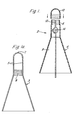
- a housing 2 is made from an electrically-conductive polymeric material, and provides electrical protection for a fibre optic cable that extends along a high voltage conductor.
- the conductor and cable are shown in outline in Figure 1, and will be described in more detail with reference to Figure 2.
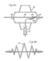
- the housing 2 comprises a first elongate part 4 that is open at each end and that has an upper generally right cylindrical portion 6 that continues downwards into a generally conical portion 8.
- the housing 2 has a second part 10, that provides a closure cap for the housing portion 6, and for this purpose the closure cap 10 has an internal thread and the cylindrical portion 6 has a mating external thread.
- the cylindrical portion 6 is bifurcated at its open end so that a slit 12 therein extends from the open end to generally circular openings in opposing side walls of the portion 6 that define a generally tubular passageway 14 therethrough.
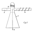
- FIG 2 shows the housing 2 of Figure 1 mounted on a high voltage uninsulated overhead conductor 16 that has a fibre optic cable 18 wound helically therearound.
- the cable 18 has the construction as herein-before described.
- the bifurcated cylindrical portion 6 of the housing 2 is spread apart so as to enlarge the slit 12 to an extent that the conductor 16 can pass therealong so as to be located within the housing passageway 14.
- the fibre optic cable 18 extends with the conductor 16 into the passageway 14, but within the housing 2 is lead off the conductor 16 and down through the open end of the conical housing portion 8.
- a conductive mastic material 20 is wrapped around the cable carrying conductor 16 where it extends into, through, and out of the housing 2 to prevent ingress of moisture into the housing along the passageway 14.
- the slit 12 is closed, and the housing cap 10 screwed on to the cylindrical portion 6, thereby sealing the top of the housing 2.
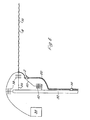
- Figure 1a shows one half 3 of a cast metal housing, that is secured to a corresponding half shell by screws or bolts so as to enclose the high voltage conductor.
- the housing formed from the half shells 3 functions electrically in the same way as the housing 2 of Figure 1, but each half shell extends integrally above and below the conductor, one on each side thereof.
- the conductor extends through a channel 5
- the fibre optic cable enters through aperture 7, and internal ribs 9 provide for securing of a protective tube (not shown) for guiding the fibre optic cable transversely away from the conductor.
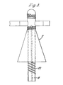
- the assembly has a housing 21 that differs from the housing 2 in its provision for entry of the fibre optic cable 18.
- the cable 18 passes away from the conductor 16 at a distance of about 50mm before the conductor enters the housing.
- the cable 18 then extends up to the housing cap 23 that has an aperture 25 that allows the cable to pass down into the housing 21.
- an inlet aperture 27 for the optical cable 18 is on the side of the cap, and the path of the cable 18 is then as shown by the broken lines in Figure 2a. Since the cable 18 enters the housing 21 through aperture 25, or 27, rather than entering along the conductor 16, as shown in Figure 2, there will be no chafing between the fibre optic cable 18, conductor 16 and the housing passage entrance. Furthermore, since the cable 18 is only away from the conductor 16 for a short distance before entering the conductive housing, no appreciable electrical stress is applied to the cable.
- the configuration of the housings 2 and 21 is such that in the region where the fibre optic cable 18 extends out from the conical portion 8 thereof, the electric stress on the cable 18 arising from the field associated with the conductor 16 is insufficient to cause damage to the cable or other adverse effects.
- parameters such as the length of the housing 2 and the angle of the conical portion 8 are selected in accordance with the voltage rating of the conductor 16. For a 33kV conductor, for example, the length of the housing extending therebelow is typically 5cm to 8cm, with the conical surface of the housing making an angle of approximately 10° with the vertical (as seen in the Figures).
- the further embodiment of the assembly shown in Figure 4 comprises a housing 24 that differs from the housing 2 in having an external screw-thread 26 at its lower open end, to which is externally threaded one end of a convoluted tubing 28.
- the protective assembly of Figure 4 has the advantage over the protective assembly of Figure 3 in that the housing 24 does not shield the tubing 28 from water, and thus minimises the risk of dry-band formation on the outer surface of the combination of housing and tubing, which, in the assembly of Figure 3, could in some circumstances give rise to electrical damage to the tubing by way of tracking and erosion.
- Figures 5a and 5b refer to alternative means 52 to the convoluted tubings 22 and 28 (of Fig. 3 and 4) for guiding a fibre optic cable 50 from a high voltage area to a lower voltage area, and is particularly, though not exclusively applicable in higher voltage applications, say above 132kV, where increased creepage path length is required.
- a fibre optic cable 50 which comprises five optical fibres 51 surrounding a strengthening member 53 in a fully water-blocked construction, is embedded in a non-tracking outer tube 52 that has sheds 54 on its outer surface.
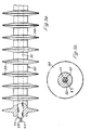
- housings 2,21 and 24 previously described are shown in Figures 6a, 6b and 6c.
- the housings of Figure 6a,6b and 6c are of open helical configuration, of metal, or fairly rigid conductive polymer, provide a substantially spherical enclosure, and are mounted on the overhead high voltage conductor.
- the housing 56 of Figure 6a is coiled around a generally vertical axis, and is clamped at diametrically-opposed locations 58,60 on to the conductor 62.
- a fibre optic cable 64 that extends helically along the condcutor 62 is guided therefrom within the housing 56 by a coiled member 66, and passes to a cable splice enclosure, shown diagramatically at 68, that is mounted on the housing 56. After splicing within the enclosure 68, the fibre optic cable leaves the housing 56 in a convoluted and/or shedded tube 70 as previously described.
- the housing 72 of Figure 6b differs from that of Figure 6a, in that it extends helically about an axis that is coincident with the overhead conductor.
- the detachment, splicing and subsequent guiding of the fibre optic cable is not shown, but may conveniently be as previously described.
- each of the enclosures 56 and 72 of Figures 6a and 6b usually have to be mounted on to the overhead conductor without it having to be cut; that is to say, they will have to be attached from the side rather than be slid on from an end of the conductor.
- the inherent rigidity required of these open configuration housings may make this rather difficult in some instances.
- the housing 73 of Figure 6c overcomes this difficulty, since it is formed from a metal or fairly rigid conductive polymeric tubular member that is secured at its mid point, put into a U-shape and then wound about a mandrel such that the limbs of the U extend axially in opposite directions.
- the housing 73 is mounted on the conductor by looping the mid point thereover and subsequently rotating the entire housing about the conductor until gripping engagement is achieved at each end of the housing.
- Figure 7 shows a housing 74 that is suitable for attachment to the convoluted tubing 80 that guides the fibre optic cable 82 from the overhead conductor to its station at earth potential and serves as a stress control arrangement, an earthing medium and earth leakage current collector. It may also serve as an enclosure for a fibre optic splice or connector.
- the housing 74 shown open in Figure 7, comprises two generally semi-cylindrical brass half-shells 76 each of which has an integrally-ridged neck portion 78 at each end for gripping the convoluted tubing 80 that guides the fibre optic cable 82.
- a further pair of generally semi-sylindrical brass half-shells 84 are located within the housing 74 and are clamped in contact with the half-shells 76 on closure of the housing.
- the non-tracking convoluted tubing 80 extends into the housing 74 and the fibre optic cable 82 exits therefrom and passes into a passageway formed by the half-shells 84.
- the larger upper part of the passageway encloses the fibre optic cable loosely, and is filled with a potting composition, and the narrower, lower part of the passageway grips the fibre optic cable firmly, but not so as to effect any damage thereto.
- the housing 74 makes direct electrical contact with the outer non-tracking tubing 80 and with the fibre optic cable 82.
- a conductive connecting stud 86 is mounted on the outside of one of the half-shells 76, and a conductor (not shown) extends therefrom to a point at earth potential.
- the housing 74 contains a splice enclosure, shown diagrammatically at 88, and the fibre optic cable passes therefrom into a further portion of the convoluted tubing 80 for onward transmission to a decoding station.
- the fibre optic cable may not need to be protected, such as by a convoluted tube, and that this may be so whether or not the high voltage stress control arrangement is applied to the cable.
- the outer pair of half shells 76 of the earth leakage current collector 74 may be dispensed with. In this case, the half shells 84 would be directly connected to earth potential.
- a high voltage conductor 30 with the fibre optic cable 18 spirally round thereon extends from one switchgear/transformer station (not shown), over a ten meter high support pole 32, and thence to a terminating switchgear/transformer station 34.
- the conductor 30 is secured to the pole 32 by tensioners 36 and is electrically isolated therefrom by insulators 38.
- the fibre optic cable 18 is lead away from the main conductor 30 along a drop wire 40, that at one end is crimped on to the conductor 30 and that at its other end is connected to a surge diverter 42 and thence to the pole 32 at earth potential.
- the drop wire 40 is at the same voltage, 33kV say, as the conductor 30.
- the fibre optic cable 18 is taken off the drop wire 40 in advance of the surge diverter 42 via the electrically-conductive housing 2 or 21, and thence through the insulated convoluted tubing 22 that is secured to the pole 32. At the bottom end of the pole the fibre optic cable 18 leaves the insulated tubing 22 and enters into switchgear (not shown), which is at earth potential. This occurs after the cable and tubing has been earthed, for example as shown by means of the housing 74.
- the conductor 30 will be accompanied by two other conductors, thus providing a three-phase power supply, but only one of the conductors will, in general be required to carry a fibre optic cable.
Landscapes
- Physics & Mathematics (AREA)
- General Physics & Mathematics (AREA)
- Optics & Photonics (AREA)
- Communication Cables (AREA)
- Ropes Or Cables (AREA)
- Cable Accessories (AREA)
- Organic Insulating Materials (AREA)
- Materials For Medical Uses (AREA)
- Insulated Conductors (AREA)
- Details Of Indoor Wiring (AREA)
Priority Applications (2)
| Application Number | Priority Date | Filing Date | Title |
|---|---|---|---|
| EP87202037A EP0303740B2 (en) | 1982-12-13 | 1983-12-13 | An assembly comprising a high voltage conductor and a fibre optic cable |
| AT83307592T ATE65330T1 (de) | 1982-12-13 | 1983-12-13 | Faseroptisches kabel. |
Applications Claiming Priority (4)
| Application Number | Priority Date | Filing Date | Title |
|---|---|---|---|
| GB8235441 | 1982-12-13 | ||
| GB8235441 | 1982-12-13 | ||
| GB838311048A GB8311048D0 (en) | 1983-04-22 | 1983-04-22 | Fibre optic cable arrangements |
| GB8311048 | 1983-04-22 |
Related Child Applications (3)
| Application Number | Title | Priority Date | Filing Date |
|---|---|---|---|
| EP87202037A Division EP0303740B2 (en) | 1982-12-13 | 1983-12-13 | An assembly comprising a high voltage conductor and a fibre optic cable |
| EP87202037.5 Division-Into | 1987-10-22 | ||
| EP90124925.0 Division-Into | 1990-12-20 |
Publications (3)
| Publication Number | Publication Date |
|---|---|
| EP0112163A2 EP0112163A2 (en) | 1984-06-27 |
| EP0112163A3 EP0112163A3 (en) | 1985-10-23 |
| EP0112163B1 true EP0112163B1 (en) | 1991-07-17 |
Family
ID=26284672
Family Applications (2)
| Application Number | Title | Priority Date | Filing Date |
|---|---|---|---|
| EP83307592A Expired - Lifetime EP0112163B1 (en) | 1982-12-13 | 1983-12-13 | Fibre optic cable arrangements |
| EP19900124925 Withdrawn EP0426204A3 (en) | 1982-12-13 | 1983-12-13 | Fibre optic cable arrangements |
Family Applications After (1)
| Application Number | Title | Priority Date | Filing Date |
|---|---|---|---|
| EP19900124925 Withdrawn EP0426204A3 (en) | 1982-12-13 | 1983-12-13 | Fibre optic cable arrangements |
Country Status (11)
| Country | Link |
|---|---|
| US (1) | US4772090A (no) |
| EP (2) | EP0112163B1 (no) |
| AT (1) | ATE123157T1 (no) |
| AU (1) | AU568618B2 (no) |
| CA (2) | CA1256727A (no) |
| DE (2) | DE3382788T3 (no) |
| GB (1) | GB2132788B (no) |
| IN (1) | IN162848B (no) |
| MY (1) | MY102488A (no) |
| NO (1) | NO171186C (no) |
| NZ (1) | NZ206555A (no) |
Families Citing this family (31)
| Publication number | Priority date | Publication date | Assignee | Title |
|---|---|---|---|---|
| GB8312892D0 (en) * | 1983-05-11 | 1983-06-15 | Raychem Ltd | Electrical insulator |
| GB8424584D0 (en) * | 1984-09-28 | 1984-11-07 | Bicc Plc | Overhead electric and optical transmission system |
| GB8428575D0 (en) * | 1984-11-12 | 1984-12-19 | Raychem Ltd | Electrical insulator |
| US4776665A (en) * | 1985-08-12 | 1988-10-11 | Siemens Aktiengesellschaft | Metal-free, self-bearing optical cable for high-tension overhead lines |
| US4770491A (en) * | 1986-05-19 | 1988-09-13 | Preformed Line Products Company | Dead end for fiber optic shield cable |
| US4832442A (en) * | 1987-07-17 | 1989-05-23 | United Ropeworks (U.S.A.) Inc. | Method and apparatus for aerial installation of fiber optic cables |
| GB2213952A (en) * | 1987-12-18 | 1989-08-23 | Focas Ltd | Optical fibre cable helically wound on electrical conductor |
| GB8817075D0 (en) * | 1988-07-18 | 1988-08-24 | Raychem Ltd | Oscillation suppressor |
| GB8817076D0 (en) * | 1988-07-18 | 1988-08-24 | Raychem Ltd | Oscillation suppression |
| US5018825A (en) * | 1989-06-14 | 1991-05-28 | Bicc Public Limited Company | Overhead optical transmission system |
| NL9001007A (nl) * | 1990-04-26 | 1991-11-18 | Nkf Kabel Bv | Mantelconstructie, in het bijzonder voor optische kabels, voor toepassing in hoogspanningsomgevingen. |
| GB2256284B (en) * | 1991-06-01 | 1995-06-07 | Northern Telecom Ltd | Voltage stress protection device |
| US5315684A (en) * | 1991-06-12 | 1994-05-24 | John Mezzalingua Assoc. Inc. | Fiber optic cable end connector |
| GB2268284B (en) * | 1992-06-19 | 1996-01-24 | Bicc Plc | Optical cable helically wound on a suspended conductor |
| US5339378A (en) * | 1993-10-06 | 1994-08-16 | The United States Of America As Represented By The Secretary Of The Navy | Torque-balanced extendable fiber optic cable |
| FR2725302B1 (fr) * | 1994-09-30 | 1997-03-14 | Sediver | Un isolateur electrique equipe de fibres optiques et son procede de fabrication |
| US5647046A (en) * | 1995-11-20 | 1997-07-08 | Alcoa Fujikura Limited | Wedge deadend to support aerial cables |
| GB9613745D0 (en) * | 1996-07-01 | 1996-09-04 | Bicc Plc | Optical connection in HV line |
| DE19713308C2 (de) * | 1997-03-29 | 1999-10-28 | Alcatel Sa | Verfahren zum Installieren eines Fernmeldekabels an einem Tragseil und Anordnung eines Fernmeldekabels an einem Tragseil |
| DE19802191B4 (de) * | 1998-01-16 | 2004-12-23 | Siemens Ag | Optischer Stromwandler mit einer Lichtwellenleiterwicklung und Verfahren zu seiner Herstellung |
| US6215940B1 (en) | 1998-06-01 | 2001-04-10 | 3M Innovative Properties Company | High voltage insulator for optical fibers |
| US6521835B1 (en) | 1999-06-14 | 2003-02-18 | K. & M. Realty Trust | Cable raceway for bridges and like structures with channel members having multiple degrees of freedom |
| US6389213B1 (en) | 2000-02-12 | 2002-05-14 | Alcoa Fujikura Limited | Deadend wedge design |
| US6831232B2 (en) | 2002-06-16 | 2004-12-14 | Scott Henricks | Composite insulator |
| US6776522B2 (en) * | 2002-10-09 | 2004-08-17 | Steven J. Syracuse | Apparatus and system for monitoring temperature of high voltage conductors |
| FR2941813B1 (fr) * | 2009-01-30 | 2016-02-26 | Areva T & D Sa | Protection de fibres optiques pour isolateurs electriques |
| EP2469661A1 (en) * | 2010-12-21 | 2012-06-27 | Alcatel Lucent | Connector with enclosure for electrical contacting means of the connector |
| US8774587B1 (en) * | 2013-01-26 | 2014-07-08 | Optisense Network, Llc | Stress control structure for optical fibers in a high voltage environment |
| US9347973B2 (en) | 2013-05-15 | 2016-05-24 | Gridview Optical Solutions, Llc | Stress control assembly and methods of making the same |
| GB2535160A (en) * | 2015-02-09 | 2016-08-17 | Skf Ab | Power generator assembly for rotating applications |
| GB2585960B (en) | 2019-11-29 | 2022-04-20 | Afl Telecommunications Europe Ltd | A system for guiding a dielectric cable from phase-to-ground potential |
Citations (6)
| Publication number | Priority date | Publication date | Assignee | Title |
|---|---|---|---|---|
| US3746424A (en) * | 1970-07-08 | 1973-07-17 | Siemens Ag | Weather-resistant light transmitting isolating device |
| FR2298807A2 (fr) * | 1975-01-21 | 1976-08-20 | Int Standard Electric Corp | Cable a fibres optiques |
| US4188088A (en) * | 1976-11-09 | 1980-02-12 | Aktieselskabet Nordiske Kabel-Og Traadfabriker | Optical element for use in optical transmission means |
| DE2929968A1 (de) * | 1979-07-24 | 1981-02-12 | Kabel Metallwerke Ghh | Lichtwellenleiter und verfahren zu seiner herstellung |
| GB2082790A (en) * | 1980-08-29 | 1982-03-10 | Nippon Telegraph & Telephone | Optical fibre in grooved central member type cable and manufacture |
| GB2085188A (en) * | 1980-09-26 | 1982-04-21 | Bicc Ltd | An improved optical cable |
Family Cites Families (15)
| Publication number | Priority date | Publication date | Assignee | Title |
|---|---|---|---|---|
| US3485940A (en) * | 1967-12-26 | 1969-12-23 | Allis Chalmers Mfg Co | Post type modular insulator containing optical and electrical components |
| US3700900A (en) * | 1969-02-06 | 1972-10-24 | Arne J Herleikson | Dual purpose transmission line |
| US3732425A (en) * | 1970-12-18 | 1973-05-08 | Gen Electric | Light conduit with double cladding |
| US3746870A (en) * | 1970-12-21 | 1973-07-17 | Gen Electric | Coated light conduit |
| DE2716922A1 (de) * | 1977-04-16 | 1978-10-19 | Rosenthal Technik Ag | Hochspannungs-freiluft-verbundisolator zur verwendung von signaluebertragungen |
| DE2901872A1 (de) * | 1979-01-18 | 1980-07-31 | Siemens Ag | Hochspannungsisoliereinrichtung, insbesondere isolator mit einem lichtleiter |
| DE3015732C2 (de) * | 1980-04-24 | 1983-06-01 | Philips Kommunikations Industrie AG, 8500 Nürnberg | Freileitungsseil mit in seinem Inneren angeordneten Lichtleitfasern |
| GB2083647B (en) * | 1980-09-15 | 1984-10-17 | Bicc Ltd | Overhead optic/electric transmission lines |
| AU543952B2 (en) * | 1981-06-03 | 1985-05-09 | Bicc Public Limited Company | Optical fibre joint for overhead transmission system |
| CA1217369A (en) * | 1981-06-18 | 1987-02-03 | Peter Harvey | Overhead electric transmission systems |
| ZA828667B (en) * | 1981-11-27 | 1983-09-28 | Bicc Plc | A flexible stranded body |
| US4496212A (en) * | 1982-02-18 | 1985-01-29 | Bicc Public Limited Company | Dead end fitting for use in overhead electric and optical transmission systems |
| JPS58162911A (ja) * | 1982-03-23 | 1983-09-27 | Furukawa Electric Co Ltd:The | 架空線添架用光通信線 |
| GB8424584D0 (en) * | 1984-09-28 | 1984-11-07 | Bicc Plc | Overhead electric and optical transmission system |
| US4610033A (en) * | 1984-12-14 | 1986-09-02 | Harvey Hubbell Incorporated | Insulator with fiber optic communication channel |
-
1983
- 1983-12-12 NZ NZ206555A patent/NZ206555A/en unknown
- 1983-12-12 AU AU22330/83A patent/AU568618B2/en not_active Expired
- 1983-12-12 CA CA000443062A patent/CA1256727A/en not_active Expired
- 1983-12-12 CA CA000443053A patent/CA1256726A/en not_active Expired
- 1983-12-12 NO NO834562A patent/NO171186C/no unknown
- 1983-12-13 AT AT87202037T patent/ATE123157T1/de not_active IP Right Cessation
- 1983-12-13 EP EP83307592A patent/EP0112163B1/en not_active Expired - Lifetime
- 1983-12-13 DE DE3382788T patent/DE3382788T3/de not_active Expired - Lifetime
- 1983-12-13 GB GB08333250A patent/GB2132788B/en not_active Expired
- 1983-12-13 DE DE8383307592T patent/DE3382345D1/de not_active Expired - Lifetime
- 1983-12-13 IN IN1521/CAL/83A patent/IN162848B/en unknown
- 1983-12-13 EP EP19900124925 patent/EP0426204A3/en not_active Withdrawn
-
1986
- 1986-09-05 US US06/904,578 patent/US4772090A/en not_active Expired - Lifetime
-
1987
- 1987-09-30 MY MYPI87002421A patent/MY102488A/en unknown
Patent Citations (6)
| Publication number | Priority date | Publication date | Assignee | Title |
|---|---|---|---|---|
| US3746424A (en) * | 1970-07-08 | 1973-07-17 | Siemens Ag | Weather-resistant light transmitting isolating device |
| FR2298807A2 (fr) * | 1975-01-21 | 1976-08-20 | Int Standard Electric Corp | Cable a fibres optiques |
| US4188088A (en) * | 1976-11-09 | 1980-02-12 | Aktieselskabet Nordiske Kabel-Og Traadfabriker | Optical element for use in optical transmission means |
| DE2929968A1 (de) * | 1979-07-24 | 1981-02-12 | Kabel Metallwerke Ghh | Lichtwellenleiter und verfahren zu seiner herstellung |
| GB2082790A (en) * | 1980-08-29 | 1982-03-10 | Nippon Telegraph & Telephone | Optical fibre in grooved central member type cable and manufacture |
| GB2085188A (en) * | 1980-09-26 | 1982-04-21 | Bicc Ltd | An improved optical cable |
Non-Patent Citations (1)
| Title |
|---|
| Distribution Developments, September 1982, pages 3-5 * |
Also Published As
| Publication number | Publication date |
|---|---|
| AU568618B2 (en) | 1988-01-07 |
| US4772090A (en) | 1988-09-20 |
| NO171186C (no) | 1993-02-03 |
| DE3382345D1 (de) | 1991-08-22 |
| EP0112163A2 (en) | 1984-06-27 |
| NO834562L (no) | 1984-06-14 |
| EP0426204A2 (en) | 1991-05-08 |
| MY102488A (en) | 1992-06-30 |
| IN162848B (no) | 1988-07-16 |
| GB8333250D0 (en) | 1984-01-18 |
| ATE123157T1 (de) | 1995-06-15 |
| EP0112163A3 (en) | 1985-10-23 |
| EP0426204A3 (en) | 1992-03-04 |
| AU2233083A (en) | 1984-06-21 |
| DE3382788D1 (de) | 1995-06-29 |
| DE3382788T3 (de) | 2001-11-15 |
| NZ206555A (en) | 1988-03-30 |
| GB2132788A (en) | 1984-07-11 |
| NO171186B (no) | 1992-10-26 |
| DE3382788T2 (de) | 1995-11-30 |
| GB2132788B (en) | 1987-09-23 |
| CA1256726A (en) | 1989-07-04 |
| CA1256727A (en) | 1989-07-04 |
Similar Documents
| Publication | Publication Date | Title |
|---|---|---|
| EP0112163B1 (en) | Fibre optic cable arrangements | |
| US3307137A (en) | Conductor termination | |
| US5936825A (en) | Rise pole termination/arrestor combination | |
| EP0172634A1 (en) | High voltage apparatus | |
| US5787217A (en) | Fiber optic ground wire cable | |
| US5687271A (en) | Shielded fiber optics cable for compatibility with high voltage power lines | |
| WO1998005098A1 (en) | Electric connection | |
| CA2376846A1 (en) | High-voltage bushing | |
| RU2484564C1 (ru) | Устройство для соединения между соединительными частями электроэнергетического оборудования | |
| US10957469B2 (en) | High voltage three-phase cable | |
| CA2076543C (en) | Electrical protection apparatus | |
| EP0303740B1 (en) | An assembly comprising a high voltage conductor and a fibre optic cable | |
| CA3162029A1 (en) | A system for guiding a dielectric cable from phase-to-ground potential | |
| KR102309365B1 (ko) | 내전압 시험 장치 | |
| Mackevich et al. | Insulation enhancement with heat-shrinkable components. III. Shielded power cable | |
| GB2169099A (en) | Fibre optic cable for use at high voltage | |
| GB2169100A (en) | Fibre optic cable for use at high voltage | |
| US8774587B1 (en) | Stress control structure for optical fibers in a high voltage environment | |
| NZ216818A (en) | Optical fibre cable: earthing of h.v. resistant sheath | |
| JPS59116704A (ja) | 光フアイバ−ケ−ブルおよびその用途 | |
| KR200177486Y1 (ko) | 절연케이블 | |
| KR20210111531A (ko) | 전력 케이블용 종단 접속함 | |
| KR20160112365A (ko) | 접속함용 슬리브 삽입 장치 및 방법 | |
| WO1992010772A1 (en) | An arrangement for use with high voltage equipment | |
| KR940005445Y1 (ko) | 지중선로 사고복구용 초고압케이블 |
Legal Events
| Date | Code | Title | Description |
|---|---|---|---|
| PUAI | Public reference made under article 153(3) epc to a published international application that has entered the european phase |
Free format text: ORIGINAL CODE: 0009012 |
|
| 17P | Request for examination filed |
Effective date: 19840110 |
|
| AK | Designated contracting states |
Designated state(s): AT BE CH DE FR IT LI NL SE |
|
| PUAL | Search report despatched |
Free format text: ORIGINAL CODE: 0009013 |
|
| AK | Designated contracting states |
Designated state(s): AT BE CH DE FR IT LI NL SE |
|
| 17Q | First examination report despatched |
Effective date: 19870320 |
|
| RAP1 | Party data changed (applicant data changed or rights of an application transferred) |
Owner name: FOCAS LIMITED |
|
| XX | Miscellaneous (additional remarks) |
Free format text: TEILANMELDUNGEN 87202037.5 UND 90124925.0 EINGEREICHT AM 13.12.83. |
|
| RAP1 | Party data changed (applicant data changed or rights of an application transferred) |
Owner name: FOCAS LIMITED |
|
| GRAA | (expected) grant |
Free format text: ORIGINAL CODE: 0009210 |
|
| AK | Designated contracting states |
Kind code of ref document: B1 Designated state(s): AT BE CH DE FR IT LI NL SE |
|
| REF | Corresponds to: |
Ref document number: 65330 Country of ref document: AT Date of ref document: 19910815 Kind code of ref document: T |
|
| XX | Miscellaneous (additional remarks) |
Free format text: TEILANMELDUNGEN 87202037.5 UND 90124925.0 EINGEREICHT AM 13.12.83. |
|
| REF | Corresponds to: |
Ref document number: 3382345 Country of ref document: DE Date of ref document: 19910822 |
|
| ET | Fr: translation filed | ||
| ITF | It: translation for a ep patent filed | ||
| PLBE | No opposition filed within time limit |
Free format text: ORIGINAL CODE: 0009261 |
|
| STAA | Information on the status of an ep patent application or granted ep patent |
Free format text: STATUS: NO OPPOSITION FILED WITHIN TIME LIMIT |
|
| 26N | No opposition filed | ||
| EAL | Se: european patent in force in sweden |
Ref document number: 83307592.2 |
|
| REG | Reference to a national code |
Ref country code: FR Ref legal event code: TP |
|
| REG | Reference to a national code |
Ref country code: CH Ref legal event code: PUE Owner name: FOCAS LIMITED TRANSFER- AFL TELECOMMUNICATIONS EUR Ref country code: CH Ref legal event code: PFA Free format text: FOCAS LIMITED,CHENEY MANOR INDUSTRIAL ESTATE,SWINDON/WILTS (GB) TRANSFER- FOCAS LIMITED,THE ADELPHI, 1-11 JOHN ADAM STREET,,LONDON WC2N 6HJ (GB) |
|
| BECA | Be: change of holder's address |
Owner name: *ALF TELECOMMUNICATIONS EUROPE LTDHAWKSWORTH INDUS |
|
| PGFP | Annual fee paid to national office [announced via postgrant information from national office to epo] |
Ref country code: AT Payment date: 20021104 Year of fee payment: 20 |
|
| PGFP | Annual fee paid to national office [announced via postgrant information from national office to epo] |
Ref country code: NL Payment date: 20021112 Year of fee payment: 20 |
|
| PGFP | Annual fee paid to national office [announced via postgrant information from national office to epo] |
Ref country code: SE Payment date: 20021122 Year of fee payment: 20 |
|
| PGFP | Annual fee paid to national office [announced via postgrant information from national office to epo] |
Ref country code: BE Payment date: 20021127 Year of fee payment: 20 |
|
| PGFP | Annual fee paid to national office [announced via postgrant information from national office to epo] |
Ref country code: CH Payment date: 20021129 Year of fee payment: 20 |
|
| PGFP | Annual fee paid to national office [announced via postgrant information from national office to epo] |
Ref country code: FR Payment date: 20021202 Year of fee payment: 20 |
|
| PGFP | Annual fee paid to national office [announced via postgrant information from national office to epo] |
Ref country code: DE Payment date: 20021230 Year of fee payment: 20 |
|
| PG25 | Lapsed in a contracting state [announced via postgrant information from national office to epo] |
Ref country code: LI Free format text: LAPSE BECAUSE OF EXPIRATION OF PROTECTION Effective date: 20031212 Ref country code: CH Free format text: LAPSE BECAUSE OF EXPIRATION OF PROTECTION Effective date: 20031212 |
|
| PG25 | Lapsed in a contracting state [announced via postgrant information from national office to epo] |
Ref country code: NL Free format text: LAPSE BECAUSE OF EXPIRATION OF PROTECTION Effective date: 20031213 Ref country code: AT Free format text: LAPSE BECAUSE OF EXPIRATION OF PROTECTION Effective date: 20031213 |
|
| BE20 | Be: patent expired |
Owner name: *ALF TELECOMMUNICATIONS EUROPE LTD Effective date: 20031213 |
|
| REG | Reference to a national code |
Ref country code: CH Ref legal event code: PL |
|
| NLV7 | Nl: ceased due to reaching the maximum lifetime of a patent |
Effective date: 20031213 |
|
| EUG | Se: european patent has lapsed |