EP0426204A2 - Fibre optic cable arrangements - Google Patents
Fibre optic cable arrangements Download PDFInfo
- Publication number
- EP0426204A2 EP0426204A2 EP90124925A EP90124925A EP0426204A2 EP 0426204 A2 EP0426204 A2 EP 0426204A2 EP 90124925 A EP90124925 A EP 90124925A EP 90124925 A EP90124925 A EP 90124925A EP 0426204 A2 EP0426204 A2 EP 0426204A2
- Authority
- EP
- European Patent Office
- Prior art keywords
- cable
- fibre optic
- housing
- optic cable
- conductor
- Prior art date
- Legal status (The legal status is an assumption and is not a legal conclusion. Google has not performed a legal analysis and makes no representation as to the accuracy of the status listed.)
- Withdrawn
Links
Images


Classifications
-
- G—PHYSICS
- G02—OPTICS
- G02B—OPTICAL ELEMENTS, SYSTEMS OR APPARATUS
- G02B6/00—Light guides; Structural details of arrangements comprising light guides and other optical elements, e.g. couplings
- G02B6/44—Mechanical structures for providing tensile strength and external protection for fibres, e.g. optical transmission cables
- G02B6/4401—Optical cables
- G02B6/4415—Cables for special applications
- G02B6/4416—Heterogeneous cables
- G02B6/4417—High voltage aspects, e.g. in cladding
- G02B6/442—Insulators
-
- G—PHYSICS
- G02—OPTICS
- G02B—OPTICAL ELEMENTS, SYSTEMS OR APPARATUS
- G02B6/00—Light guides; Structural details of arrangements comprising light guides and other optical elements, e.g. couplings
- G02B6/44—Mechanical structures for providing tensile strength and external protection for fibres, e.g. optical transmission cables
- G02B6/4401—Optical cables
- G02B6/4415—Cables for special applications
- G02B6/4416—Heterogeneous cables
- G02B6/4417—High voltage aspects, e.g. in cladding
- G02B6/442—Insulators
- G02B6/4421—Insulators with helical structure of optical fibre, e.g. fibres wound around insulators
Definitions
- This invention relates to arrangements including fibre optic cables, and in particular to arrangements including fibre optic cables suitable for installation closely adjacent to, or in physical contact with high voltage equipment such as a high voltage conductor.
- high voltage equipment equipment rated at 1kV or above, and may be for example a 33kV or 400kV power conductor.
- the present invention provides a fibre optic cable arrangement whereby the cable may be used in close proximity to, and subject to the electric field of, high voltage equipment, for example high voltage conductors, switchgear, transformers, motors and generators, and whereby the cable may be routed through or around equipment at different potentials, including earth potential, without adversely affecting the operation of the cable.
- high voltage equipment for example high voltage conductors, switchgear, transformers, motors and generators
- the fibre optic cable may transmit optically encoded data, such data may be in either digital or analogue form, and such data may be used for the monitoring and control of an electrical network of which the conductor, for example, forms part.
- the cable may be employed for the transmission of data not relevant to the operation of the network, such data including telecommunications and similar signals normally carried by fibre optic links.
- the fibre optic cable could itself serve as a sensor to monitor the operating parameters of an electrical system, including those of the conductor.
- an arrangement comprising high voltage equipment, a fibre optic cable that is located in a region so as to be subject to the electric field of the equipment and to the flow of leakage current along the cable jacket, and electrically conductive means mounted on the cable so as to conduct to a point at earth potential any leakage current flowing along the cable jacket.
- the high voltage equipment may be a high voltage electrical conductor, which may be an overhead line conductor, or it may be other equipment such as switchgear or a transformer.
- the cable may extend along or alongside, and preferably be helically wrapped around, the conductor.
- the means for conducting leakage current to earth which may be an earth leakage current collector or a means for reducing the leakage current density, may conveniently comprise two electrically-conducting half-shells clamped directly on to the cable.
- the earth leakage current collector may further comprise means, similar to the said electrically conductive means, for connecting such member to earth and thus for earthing any leakage current flowing therealong.
- the tubular or other protection member extends all the way along the fibre optic cable between the stress control means and the leakage current collecting means.
- the earth leakage current collector may alternatively be provided by a hybrid arrangement comprising a pair of insulating, for example porcelain, half shells that are mounted on the cable and that abut a pair of metal earthing half-shells that are mounted on the cable in the direction of the lower potential from the insulating half-shells.
- a hybrid arrangement comprising a pair of insulating, for example porcelain, half shells that are mounted on the cable and that abut a pair of metal earthing half-shells that are mounted on the cable in the direction of the lower potential from the insulating half-shells.
- Environmental protection, for example from water or salt or other pollutants, of the fibre optic cable as it is guided to the electrically conductive means may be provided by an electrically-insulating, non-tracking, weather resistant and preferably tubular member that interengages with the conductive means and extends with the cable away therefrom, advantageously all the way to the high voltage equipment.
- This member may be convoluted and/or shedded on its outer surface, for extending the creepage path length. Its inner surface may be convoluted, and it may be filled to prevent water deposition therealong.
- the fibre optic cable may be loosely disposed within the tubular member.
- U.S. Patent No. 3746424 discloses an isolating device for guiding an optical fibre bundle from a current measuring device associated with a high voltage conductor to a detection device at earth potential, in which the isolating device has a plurality of skirts along its length.
- the fibre optic bundle there is no provision for, for example, the fibre optic bundle to extend externally of the conductor so as to be subject to its electric field.
- the jacket of the fibre optic cable is of a substantially electrically non-tracking material, and may be electrically insulating, substantially, non-wetting and weather resistant.
- the cable may be applied to the surface of a conductor that is energised.
- the coating must be sufficiently robust to resist electrical activity resulting from the electrical field surrounding the conductor.
- Stress control in high voltage cable terminations can be effected either resistively or capacitively by coupling with the energised centre conductor of the cable.
- a fibre optic cable however, has no such conductor and in some respects can be considered to be more similar to a high voltage insulator.
- a high voltage insulator is designed to control surface leakage currents by the provision of sheds on its surface. The sheds have several functions: increasing the creepage distance, often to more than three times the actual phase-to-ground distance; provision of numerous "dry" areas of relatively high resistance, which can maintain the leakage currents at acceptably low levels; and the provision of protected areas which limit the deposition of pollutants.
- the diameter of a fibre optic cable is typically one tenth to one hundredth that of a high voltage insulator and the fibre optic cable has negligible strength.
- the provision of shedded areas to produce the same result as in typical high voltage insulators is clearly impractical and other solutions must therefore be sought to both problems.
- Insulators are of solid core or occasionally oil filled construction to eliminate, or at least to reduce, internal discharge activity which might result in failure.
- optical fibres are frequently of "loose tube” construction, or laid up in such a way as to form extended internal voids. Since air is a good dielectric material it might be supposed that such voids in so small a structure would have negligible affect. However, experience and experiment have shown that such voids are detrimental to longer term service life and must either be eliminated or their potentially detrimental effects curtailed in some other way.
- the fibre optic cable used in the arrangement of the invention may be of any suitable configuration, and may, for example, comprise one or more optic fibres, each within its individual sheath or sheaths, and where more than one fibre is present, these may be grouped together within a single outer sheath.
- fibre optic cable Two configurations of high voltage fibre optic cable are proposed which may be used separately or in conjunction with one another. It is envisaged that the fibre optic cable may have other components, in addition to those specifically mentioned.
- the first configuration of fibre optic cable may comprise a substantially non-tracking outer jacket, a non metallic strength member, one or more fibre optic elements and a compatible, protective filler.
- the filler is arranged substantially to eliminate, or at least inhibit, the formation or existence of significant elongate voids, or the significant transmission of moisture within the structure in the event of puncture of said outer protective jacket.
- the same filler may be used to achieve each of these results, or separate fillers may be required.
- the compatible filler may be incorporated into the construction during manufacture, and may comprise a similar material to the jacket; a gum-like material, for example based on silicone, butyl, or ethylene propylene elastomers; a wax or jelly-like material for example a petroleum jelly; or an oil which may be incorporated during manufacture or subsequently drawn into the interstices of the construction.
- the filler may be of the same material as, and integral with, the cable jacket, such that filling of the cable, for example by complete impregration of a braided component thereof, is effected when the jacket is added during manufacture.
- the jacket and filler may be subsequently cross-linked by high energy radiation or chemical means.
- the second configuration of high voltage fibre optic cable may comprise a conductive outer jacket, which may be of metal or polymer, a strength member and one or more fibre optic elements.
- the more straightforward construction, and the conductive outer sheath of the second configuration cable make it particularly, though not exclusively, suited to installation adjacent to a live conductor at high voltages, whereas the first configuration cable is particularly though not exclusively, suited to the transition from high voltage to ground potential.
- a cable of the second configuration being particularly suited to operation at a single potential, may be connected to a cable of the first configuration to effect a transition between high voltage and ground potential.
- the material of the outer jacket of the fibre optic cable would be selected in dependence on the electrical environment in which it is located.
- a conductive outer jacket of a material having a resistance of less than about 106 ohms per cm of its length would be suitable.
- Such a material ensures in general, that the potential of the cable jacket is sufficiently close to that of the conductor so that any surface discharge activity that may take place on the cable will be insufficient to cause any damage thereto.
- the cable jacket has a protective outer surface.
- the outer jacket should have a resistance of at least about 107 or 108 ohms per cm length and be non-tracking.
- the fibre optic cable may be provided with a non-tracking jacket and be disposed within a metal tube.
- a metal tube would enhance the mechanical protection and moisture proofing of the cable.
- the metal tube would be removed at the cable end and thus subject the cable to axial ingress of moisture.
- water blocking of the cable would be advantageous. Filling or blocking the cable is particularly important where the cable extends between locations at appreciably different voltages, for example from a conductor at phase voltage to ground potential.
- ingress of moisture at any part of the cable may cause long term damage to its optical properties, if water comes into contact with the glass fibre, for example.
- the non-tracking outer jacket material used in the lower potential may be a replacement for said conductive outer jacket material, or alternatively may be provided as a further layer thereover.
- the cable may be located in a tubular member, and may but and need not be environmentally sealed.
- a protective housing for the tube may be perforated, so as to avoid the build-up of moisture for example.
- the arrangement of the invention may also incorporate electrical stress control means, wherein any electrical stress, arising from the electric field produced by the conductor or other high voltage equipment, to which the fibre optic cable is subjected, is substantially insufficient to cause damage to the fibre optic cable, for example by puncturing that allows water ingress, or other adverse effects such as radiated interference, or spurious optical signals.
- the stress control means may be arranged to enclose the fibre optic cable in the region where the cable leaves the immediate vicinity of the field of the conductor.
- the electrical stress control means comprises an electrically-conductive housing, of conductive polymeric material, or metal, for example, that is mounted on the equipment, and the cable is arranged to leave the equipment and pass towards a site of significantly different electrical potential, eg earth potential, through the appreciably-reduced field environment of the housing.
- a site of significantly different electrical potential eg earth potential
- the housing may thus provide an enclosure that is substantially free from the electric field associated with the high voltage conductor, so that the fibre optic cable, which is initially at the voltage of the conductor along which it may, in use, extend, can leave the conductor in the vicinity of the housing and can safely be lead away from the high voltage conductor to, or at least towards, a position at a much lower potential.
- the housing need extend away from the conductor only so far as to ensure that when the fibre optic cable exits therefrom into any electric field of the conductor, the field strength is too small to effect any substantial damage of the cable or have such adverse effects as discussed above.
- the configuration of the housing may be such as to reduce the effect of the electric stress from the field of the conductor.
- the cable exit of the housing may open outwards away from the conductor, being conical or bell-shape for example.
- the configuration, including the shaping and size, of the housing may be different for high voltage conductors of different voltage ratings, so as to optimise the electrical protection of the fibre optic cable.
- the function of the housing is to act in a manner similar to that of a Faraday Cage, and thus it need not completely physically enclose the fibre optic cable.
- the housing will not, in general, be required to carry any appreciable electric current.
- the stress control effect may be achieved by a partially open configuration, for example a lattice work wrapping of electrically conductive material around the region where the fibre optic cable leaves the immediate vicinity of the electric field of the high voltage conductor.
- an electrically-conductive housing may be arranged to protect the cable at the location where the cable is brought to earth potential.
- the housing has a passage therethrough and an inlet and an outlet spaced from but in communication with the passage, whereby the high voltage conductor extends through the passage,and supports the housing, and the fibre optic cable is arranged to leave the conductor just outside the housing, to enter through the inlet and to exit from the housing through said outlet.
- the fibre optic cable should leave the conductor, and thus enter the housing, at a position close enough to the housing such that no significant potential drop exists along the fibre optic cable.
- the fibre optic cable should not extend laterally of the high voltage conductor for more than about three times the diameter of the conductor before entering the conductive housing.
- the fibre optic cable may enter the housing into the passage together with the conductor, and thus leave the conductor within the housing itself.
- the housing may comprise two half shells that are secured together, by screws for example, so as to allow the conductor to pass therethrough and so as to extend transversely thereof, preferably flaring outwardly, to guide the fibre optic cable away from the conductor.
- the housing may be split at one end, for example by being bifurcated, so that it can be pushed on to the conductor, and may be provided with a closure cap, as a screw fit, push fit or snap-on for example.
- the housing may be a two-part housing with a suitable closure mechanism, or be of a one-part wraparound configuration.
- the housing may be substantially elongate, or may have some other shape, for example a T-shape whereby the arms of the T extend along the conductor.
- the housing is generally elongate, having bifurcations at one end leading to a transverse passage receiving the conductor, with an outlet at the other end of the housing leading the fibre optic cable away from the conductor.
- the housing is environmentally sealed on to the high voltage conductor, advantageously by means of electrically conducting mastic or sealant.
- the invention thus allows a fibre optic cable to be mounted externally of a high voltage conductor, for example, and to be removed therefrom, or to provide for splicing thereto, at any position along the length of the conductor, and to be brought safely to a location of appreciably different electrical potential, without having to terminate, splice, or otherwise interfere with the conductor itself.
- the invention also allows a fibre optic cable to extend safely from a sensor associated with high voltage electrical equipment to a much lower, for example earth, potential.
- optical fibre may be achieved by completely filling the region between the cable and the enclosing housing and/or tubular insulating member, which preferably extends all the way between the stress control housing and the electrically conductive current collector means.
- One way of achieving this is to arrange for the insulating member to be shrinkable, for example heat-shrinkable, on to the optical cable, preferably with an internal sealant or adhesive coating, for example a mastic or a hot melt adhesive.
- Another way is to ensure that the region between the optical cable and the insulating member is filled with an oil, resin, foam, or other suitable insulating medium. With such provision, the sealing of the housing on to the conductor is not so important, and may be dispensed with entirely.
- the or a further stress control means may be located at the position where the cable, initially subject to a high voltage, approaches or reaches a much lower, for example earth, potential. Such stress control means may then act as the earth leakage current collector of the arrangement, and thus ensure safe earthing of the cable without causing any appreciable electrical damage thereto or minimise other adverse effects of the leakage current.
- a method of providing electrical protection for a fibre optic cable that is located in a region so as to be subject to the electric field of high voltage equipment and to the flow of leakage current along a jacket of the cable, wherein electrically conductive means is mounted on the cable and is arranged to conduct any leakage current flowing along the cable jacket to a point at earth potential.
- the invention may provide an arrangement that comprises both of the above-mentioned features, namely means for earthing any leakage current flowing along the cable, and environmental protection means for the cable as it passes from a location at one potential to a location at an appreciably different potential, for example from high voltage to earth.
- One advantageous arrangement fo the invention comprises a fibre optic cable associated with a high voltage conductor, which may be an overhead conductor, stress control means arranged such that substantially no electrical damage is caused to the cable where it leaves the conductor, a protective tubular member for guiding the cable towards a region of significantly lower electrical potential, for example earth, and further stress control means for electrically terminating the cable without electrical damage at said lower potential.
- a housing 2 is made from an electrically-conductive polymeric material, and provides electrical protection for a fibre optic cable that extends along a high voltage conductor.
- the conductor and cable are shown in outline in Figure 1, and will be described in more detail with reference to Figure 2.
- the housing 2 comprises a first elongate part 4 that is open at each end and that has an upper generally right cylindrical portion 6 that continues downwards into a generally conical portion 8.
- the housing 2 has a second part 10, that provides a closure cap for the housing portion 6, and for this purpose the closure cap 10 has an internal thread and the cylindrical portion 6 has a mating external thread.
- the cylindrical portion 6 is bifurcated at its open end so that a slit 12 therein extends from the open end to generally circular openings in opposing side walls of the portion 6 that define a generally tubular passageway 14 therethrough.
- FIG 2 shows the housing 2 of Figure 1 mounted on a high voltage uninsulated overhead conductor 16 that has a fibre optic cable 18 wound helically therearound.
- the cable 18 may have any suitable construction as hereinbefore described.
- the bifurcated cylindrical portion 6 of the housing 2 is spread apart so as to enlarge the slit 12 to an extent that the conductor 16 can pass therealong so as to be located within the housing passageway 14.
- the fibre optic cable 18 extends with the conductor 16 into the passageway 14, but within the housing 2 is lead off the conductor 16 and down through the open end of the conical housing portion 8.
- a conductive mastic material 20 is wrapped around the cable carrying conductor 16 where it extends into, through, and out of the housing 2 to prevent ingress of moisture into the housing along the passageway 14.
- the slit 12 is closed, and the housing cap 10 screwed on to the cylindrical portion 6, thereby sealing the top of the housing 2.
- Figure 1a shows one half 3 of a cast metal housing, that is secured to a corresponding half shell by screws or bolts so as to enclose the high voltage conductor.
- the housing formed from the half shells 3 functions electrically in the same way as the housing 2 of Figure 1, but each half shell extends integrally above and below the conductor, one on each side thereof.
- the conductor extends through a channel 5
- the fibre optic cable enters through aperture 7, and internal ribs 9 provide for securing of a protective tube (not shown) for guiding the fibre optic cable transversely away from the conductor.
- the assembly has a housing 21 that differs from the housing 2 in its provision for entry of the fibre optic cable 18.
- the cable 18 passes away from the conductor 16 at a distance of about 50mm before the conductor enters the housing.
- the cable 18 then extends up to the housing cap 23 that has an aperture 25 that allows the cable to pass down into the housing 21.
- an inlet aperture 27 for the optical cable 18 is on the side of the cap, and the path of the cable 18 is then as shown by the broken lines in Figure 2a. Since the cable 18 enters the housing 21 through aperture 25, or 27, rather than entering along the conductor 16, as shown in Figure 2, there will be no chafing between the fibre optic cable 18, conductor 16 and the housing passage entrance. Furthermore, since the cable 18 is only away from the conductor 16 for a short distance before entering the conductive housing, no appreciable electrical stress is applied to the cable.
- the configuration of the housings 2 and 21 is such that in the region where the fibre optic cable 18 extends out from the conical portion 8 thereof, the electric stress on the cable arising from the field associated with the conductor 16 is insufficient to cause damage to the cable or other adverse effects.
- parameters such as the length of the housing 2 and the angle of the conical portion 8 are selected in accordance with the voltage rating of the conductor 16. For a 33kV conductor, for example, the length of the housing extending therebelow is typically 5cm to 8cm, with the conical surface of the housing making an angle of approximately 10° with the vertical (as seen in the Figures).
- the further embodiment of the assembly shown in Figure 4 comprises a housing 24 that differs from the housing 2 in having an external screw-thread 26 at its lower open end, to which is externally threaded one end of a convoluted tubing 28.
- the protective assembly of Figure 4 has the advantage over the protective assembly of Figure 3 in that the housing 24 does not shield the tubing 28 from water, and thus minimises the risk of dry-band formation on the outer surface of the combination of housing and tubing, which, in the assembly of Figure 3, could in some circumstances give rise to electrical damage to the tubing by way of tracking and erosion.
- Figures 5a and 5b refer to alternative means to the convoluted tubings 22 and 28 for guiding a fibre optic cable from a high voltage area to a lower voltage area, and is particularly, though not exclusively applicable in higher voltage applications, say above 132kV, where increased creepage path length is required.
- a fibre optic cable 50 which comprises five fibre optical fibres surrounding a strengthening member in a fully water-blocked construction, is embedded in a non-tracking outer jacket 52 that has sheds 54 on its outer surface.
- housings 2,21 and 24 previously described are shown in Figures 6a, 6b and 6c.
- the housings of Figure 6a,6b and 6c are of open helical configuration, of metal, or fairly rigid conductive polymer, provide a substantially spherical enclosure, and are mounted on the overhead high voltage conductor.
- the housing 56 of Figure 6a is coiled around a generally vertical axis, and is clamped at diametrically-opposed locations 58,60 on to the conductor 62.
- a fibre optic cable 64 that extends helically along the condcutor 62 is guided therefrom within the housing 56 by a coiled member 66, and passes to a cable splice enclosure, shown diagramatically at 68, that is mounted on the housing 56. After splicing within the enclosure 68, the fibre optic cable leaves the housing 56 in a convoluted and/or shedded tube 70 as previously described.
- the housing 72 of Figure 6b differs from that of Figure 6a, in that it extends helically about an axis that is coincident with the overhead conductor.
- the detachment, splicing and subsequent guiding of the fibre optic cable is not shown, but may conveniently be as previously described.
- each of the enclosures 56 and 72 of Figures 6a and 6b usually have to be mounted on to the overhead conductor without it having to be cut; that is to say, they will have to be attached from the side rather than be slid on from an end of the conductor.
- the inherent rigidity required of these open configuration housings may make this rather difficult in some instances.
- the housing 73 of Figure 6c overcomes this difficulty, since it is formed from a metal or fairly rigid conductive polymeric tubular member that is secured at its mid point, put into a U-shape and then wound about a mandrel such that the limbs of the U extend axially in opposite directions.
- the housing 73 is mounted on the conductor by looping the mid point thereover and subsequently rotating the entire housing about the conductor until gripping engagement is achieved at each end of the housing.
- Figure 7 shows a housing 74 that is suitable for attachment to the convoluted tubing that guides the fibre optic cable from the overhead conductor to its station at earth potential and serves as a stress control arrangement, an earthing medium and earth leakage current collector. It may also serve as an enclosure for a fibre optic splice or connector.
- the housing 74 shown open in Figure 7, comprises two generally semi-cylindrical brass half-shells 76 each of which has an integrally-ridged neck portion 78 at each end for gripping the convoluted tubing 80 that guides the fibre optic cable 82.
- a further pair of generally semi-sylindrical brass half-shells 84 are located within the housing 74 and are clamped in contact with the half-shells 76 on closure of the housing.
- the non-tracking convoluted tubing 80 extends into the housing 74 and the fibre optic cable 82 exits therefrom and passes into a passageway formed by the half-shells 84.
- the larger upper part of the passageway encloses the fibre optic cable loosely, and is filled with a potting composition, and the narrower, lower part of the passageway grips the fibre optic cable firmly, but not so as to effect any damage thereto.
- the housing 74 makes direct electrical contact with the outer non-tracking tubing 80 and with the fibre optic cable 82.
- a conductive connecting stud 86 is mounted on the outside of one of the half-shells 76, and a conductor (not shown) extends therefrom to a point at earth potential.
- the housing 74 contains a splice enclosure, shown diagrammatically at 88, and the fibre optic cable passes therefrom into a further portion of the convoluted tubing 80 for onward transmission to a decoding station.
- the fibre optic cable may not need to be protected, such as by a convoluted tube, and that this may be so whether or not the high voltage stress control arrangement is applied to the cable.
- the outer pair of half shells 76 of the earth leakage current collector 74 may be dispensed with. In this case, the half shells 84 would be directly connected to earth potential.
- a high voltage conductor 30 with the fibre optic cable 18 spirally round thereon extends from one switchgear/transformer station (not shown), over a ten meter high support pole 32, and thence to a terminating switchgear/transformer station 34.
- the conductor 30 is secured to the pole 32 by tensioners 36 and is electrically isolated therefrom by insulators 38.
- the fibre optic cable 18 is lead away from the main conductor 30 along a drop wire 40, that at one end is crimped on to the conductor 30 and that at its other end is connected to a surge diverter 42 and thence to the pole 32 at earth potential.
- the drop wire 40 is at the same voltage, 33kV say, as the conductor 30.
- the fibre optic cable 18 is taken off the drop wire 40 in advance of the surge diverter 42 via the electrically-conductive housing 2 or 21, and thence through the insulated convoluted tubing 22 that is secured to the pole 32. At the bottom end of the pole the fibre optic cable 18 leaves the conductive tubing 22 and enters into switchgear (not shown), which is at earth potential. This occurs as shown by means of the housing 74.
- the conductor 30 will be accompanied by two other conductors, thus providing a three-phase power supply, but only one of the conductors will, in general be required to carry a fibre optic cable.
Abstract
Description
- This invention relates to arrangements including fibre optic cables, and in particular to arrangements including fibre optic cables suitable for installation closely adjacent to, or in physical contact with high voltage equipment such as a high voltage conductor.
- By high voltage equipment is meant equipment rated at 1kV or above, and may be for example a 33kV or 400kV power conductor.
- The use of a fibre optic cable in association with a high voltage conductor is known from UK Patent Application Publication Nos. 2083647A and 2101351A. These publications disclose arrangements in which a fibre optic cable extends inside a high voltage conductor and thus is not subject to its electric field gradient. The arrangements provide for the cable to leave the conductor in a metal housing and to extend through a porcelain chamber filled with insulating oil to a location at earth potential. An article in Distribution Developments (September, 1982) discloses the mounting of a fibre optic cable having an outer sheath manufactured from a non-tracking low erosion compound on an overhead conductor.
- It is an object of the invention to minimise detrimental effects of leakage current or induced current, such as radiated interference and spurious optical signals.
- It is another object of the present invention to prevent, or at least to reduce damage to a fibre optic cable that is to be located in the vicinity of a high voltage conductor, including the region where the cable leaves the conductor, and that accordingly is subject to flow of leakage current therealong.
- The present invention provides a fibre optic cable arrangement whereby the cable may be used in close proximity to, and subject to the electric field of, high voltage equipment, for example high voltage conductors, switchgear, transformers, motors and generators, and whereby the cable may be routed through or around equipment at different potentials, including earth potential, without adversely affecting the operation of the cable.
- The fibre optic cable may transmit optically encoded data, such data may be in either digital or analogue form, and such data may be used for the monitoring and control of an electrical network of which the conductor, for example, forms part. However, the cable may be employed for the transmission of data not relevant to the operation of the network, such data including telecommunications and similar signals normally carried by fibre optic links. Furthermore, it is envisaged that the fibre optic cable could itself serve as a sensor to monitor the operating parameters of an electrical system, including those of the conductor.
- In accordance with one aspect of the present invention, there is provided an arrangement comprising high voltage equipment, a fibre optic cable that is located in a region so as to be subject to the electric field of the equipment and to the flow of leakage current along the cable jacket, and electrically conductive means mounted on the cable so as to conduct to a point at earth potential any leakage current flowing along the cable jacket.
- The high voltage equipment may be a high voltage electrical conductor, which may be an overhead line conductor, or it may be other equipment such as switchgear or a transformer.
- The cable may extend along or alongside, and preferably be helically wrapped around, the conductor.
- The means for conducting leakage current to earth, which may be an earth leakage current collector or a means for reducing the leakage current density, may conveniently comprise two electrically-conducting half-shells clamped directly on to the cable. When the cable is itself enclosed within an environmentally-protecting member, as hereinafter described, the earth leakage current collector may further comprise means, similar to the said electrically conductive means, for connecting such member to earth and thus for earthing any leakage current flowing therealong. Advantageously, the tubular or other protection member extends all the way along the fibre optic cable between the stress control means and the leakage current collecting means.
- The earth leakage current collector may alternatively be provided by a hybrid arrangement comprising a pair of insulating, for example porcelain, half shells that are mounted on the cable and that abut a pair of metal earthing half-shells that are mounted on the cable in the direction of the lower potential from the insulating half-shells. Such an arrangement is disclosed and claimed in EP-A-0125884.
- Environmental protection, for example from water or salt or other pollutants, of the fibre optic cable as it is guided to the electrically conductive means may be provided by an electrically-insulating, non-tracking, weather resistant and preferably tubular member that interengages with the conductive means and extends with the cable away therefrom, advantageously all the way to the high voltage equipment. This member may be convoluted and/or shedded on its outer surface, for extending the creepage path length. Its inner surface may be convoluted, and it may be filled to prevent water deposition therealong. Alternatively, the fibre optic cable may be loosely disposed within the tubular member.
- U.S. Patent No. 3746424 discloses an isolating device for guiding an optical fibre bundle from a current measuring device associated with a high voltage conductor to a detection device at earth potential, in which the isolating device has a plurality of skirts along its length. However, there is no provision for, for example, the fibre optic bundle to extend externally of the conductor so as to be subject to its electric field.
- Advantageously, the jacket of the fibre optic cable, either along its whole length, or at least in the region where it extends from high voltage to a lower, for example earth, potential, is of a substantially electrically non-tracking material, and may be electrically insulating, substantially, non-wetting and weather resistant. Thus, if such a jacket, or coating, is applied to the fibre optic cable throughout its length, the cable may be applied to the surface of a conductor that is energised. For this latter application to be successful, that is to say for the arrangement to be such that integrity of the cable, and thus the transmitted optical signal, remains intact, the coating must be sufficiently robust to resist electrical activity resulting from the electrical field surrounding the conductor. Three formidable problems must be overcome before the arrangement can be expected to provide acceptable long term performance. These problems include: stress control at the point where the fibre optic cable leaves the high voltage conductor and where it approaches ground, or earth, potential; control of surface leakage currents which will flow along the surface of the fibre optic cable sheath as a result of contamination; and the maintenance of the integrity of the fibre optic cable after prolonged outdoor exposure to high electric stress. Problems of these general kinds are known within the electricity distribution industry, and in many instances typical devices including insulators, cable terminations and the like, which must of necessity encompass phase and ground potential, have been designed with these problems in mind.
- However, solutions appropriate to insulators or high voltage power cables are not appropriate to fibre optic cables.
- Stress control in high voltage cable terminations can be effected either resistively or capacitively by coupling with the energised centre conductor of the cable. A fibre optic cable, however, has no such conductor and in some respects can be considered to be more similar to a high voltage insulator. A high voltage insulator is designed to control surface leakage currents by the provision of sheds on its surface. The sheds have several functions: increasing the creepage distance, often to more than three times the actual phase-to-ground distance; provision of numerous "dry" areas of relatively high resistance, which can maintain the leakage currents at acceptably low levels; and the provision of protected areas which limit the deposition of pollutants.
- By comparison, the diameter of a fibre optic cable is typically one tenth to one hundredth that of a high voltage insulator and the fibre optic cable has negligible strength. The provision of shedded areas to produce the same result as in typical high voltage insulators is clearly impractical and other solutions must therefore be sought to both problems.
- Insulators are of solid core or occasionally oil filled construction to eliminate, or at least to reduce, internal discharge activity which might result in failure. By comparison optical fibres are frequently of "loose tube" construction, or laid up in such a way as to form extended internal voids. Since air is a good dielectric material it might be supposed that such voids in so small a structure would have negligible affect. However, experience and experiment have shown that such voids are detrimental to longer term service life and must either be eliminated or their potentially detrimental effects curtailed in some other way.
- The fibre optic cable used in the arrangement of the invention may be of any suitable configuration, and may, for example, comprise one or more optic fibres, each within its individual sheath or sheaths, and where more than one fibre is present, these may be grouped together within a single outer sheath.
- Two configurations of high voltage fibre optic cable are proposed which may be used separately or in conjunction with one another. It is envisaged that the fibre optic cable may have other components, in addition to those specifically mentioned.
- The first configuration of fibre optic cable may comprise a substantially non-tracking outer jacket, a non metallic strength member, one or more fibre optic elements and a compatible, protective filler.
- The filler is arranged substantially to eliminate, or at least inhibit, the formation or existence of significant elongate voids, or the significant transmission of moisture within the structure in the event of puncture of said outer protective jacket. The same filler may be used to achieve each of these results, or separate fillers may be required.
- The compatible filler may be incorporated into the construction during manufacture, and may comprise a similar material to the jacket; a gum-like material, for example based on silicone, butyl, or ethylene propylene elastomers; a wax or jelly-like material for example a petroleum jelly; or an oil which may be incorporated during manufacture or subsequently drawn into the interstices of the construction. The filler may be of the same material as, and integral with, the cable jacket, such that filling of the cable, for example by complete impregration of a braided component thereof, is effected when the jacket is added during manufacture.
- The jacket and filler may be subsequently cross-linked by high energy radiation or chemical means.
- The second configuration of high voltage fibre optic cable may comprise a conductive outer jacket, which may be of metal or polymer, a strength member and one or more fibre optic elements.
- The more straightforward construction, and the conductive outer sheath of the second configuration cable make it particularly, though not exclusively, suited to installation adjacent to a live conductor at high voltages, whereas the first configuration cable is particularly though not exclusively, suited to the transition from high voltage to ground potential. Thus, a cable of the second configuration, being particularly suited to operation at a single potential, may be connected to a cable of the first configuration to effect a transition between high voltage and ground potential.
- It will be appreciated that the material of the outer jacket of the fibre optic cable would be selected in dependence on the electrical environment in which it is located. For a cable subject to a high voltage field, for example by being wound on an uninsulated overhead power conductor, a conductive outer jacket of a material having a resistance of less than about 10⁶ ohms per cm of its length would be suitable. Such a material ensures in general, that the potential of the cable jacket is sufficiently close to that of the conductor so that any surface discharge activity that may take place on the cable will be insufficient to cause any damage thereto. However, if such a jacket were insulating, having a resistance of more than about 10⁷ or 10⁸ ohms per cm length, then it should either be encased in a further jacket of a non-tracking insulating material, or made entirely from such non-tracking insulating material. Thus, even though there may be an appreciable difference in potential between the conductor and the cable, the cable jacket has a protective outer surface. Where the fibre optic cable is required to extend between phase potential and ground potential, the outer jacket should have a resistance of at least about 10⁷ or 10⁸ ohms per cm length and be non-tracking. If the resistance of the outer jacket of such a cable were of significantly lower potential, then the leakage current flowing therealong, and the power dissipation, could be unacceptably high. Thus, it will be understood that at higher voltages electrical tracking along the cable surface has to be minimised, whilst at lower voltages the leakage current has to be maintained within an acceptable limit. The particular resistance limits will, accordingly, be dependant on the operating voltage to which the cable is subject.
- Although usually it will be desirable to provide filling for the fibre optic cable only when an insulating outer covering is provided, it may in some circumstances be advantageous to fill the cable when it has a conductive outer covering. For example, the fibre optic cable may be provided with a non-tracking jacket and be disposed within a metal tube. Such a tube would enhance the mechanical protection and moisture proofing of the cable. However, on splicing or terminating such a cable, the metal tube would be removed at the cable end and thus subject the cable to axial ingress of moisture. In such circumstances, water blocking of the cable would be advantageous. Filling or blocking the cable is particularly important where the cable extends between locations at appreciably different voltages, for example from a conductor at phase voltage to ground potential. However, ingress of moisture at any part of the cable may cause long term damage to its optical properties, if water comes into contact with the glass fibre, for example.
- The non-tracking outer jacket material used in the lower potential, and preferably also in the transition region from the high potential region, may be a replacement for said conductive outer jacket material, or alternatively may be provided as a further layer thereover.
- The cable may be located in a tubular member, and may but and need not be environmentally sealed. For example a protective housing for the tube may be perforated, so as to avoid the build-up of moisture for example.
- The arrangement of the invention may also incorporate electrical stress control means, wherein any electrical stress, arising from the electric field produced by the conductor or other high voltage equipment, to which the fibre optic cable is subjected, is substantially insufficient to cause damage to the fibre optic cable, for example by puncturing that allows water ingress, or other adverse effects such as radiated interference, or spurious optical signals.
- The stress control means may be arranged to enclose the fibre optic cable in the region where the cable leaves the immediate vicinity of the field of the conductor.
- Preferably, the electrical stress control means comprises an electrically-conductive housing, of conductive polymeric material, or metal, for example, that is mounted on the equipment, and the cable is arranged to leave the equipment and pass towards a site of significantly different electrical potential, eg earth potential, through the appreciably-reduced field environment of the housing.
- The housing may thus provide an enclosure that is substantially free from the electric field associated with the high voltage conductor, so that the fibre optic cable, which is initially at the voltage of the conductor along which it may, in use, extend, can leave the conductor in the vicinity of the housing and can safely be lead away from the high voltage conductor to, or at least towards, a position at a much lower potential. Thus, the housing need extend away from the conductor only so far as to ensure that when the fibre optic cable exits therefrom into any electric field of the conductor, the field strength is too small to effect any substantial damage of the cable or have such adverse effects as discussed above. To this end, the configuration of the housing may be such as to reduce the effect of the electric stress from the field of the conductor. Advantageously the cable exit of the housing may open outwards away from the conductor, being conical or bell-shape for example. It will be appreciated that the configuration, including the shaping and size, of the housing may be different for high voltage conductors of different voltage ratings, so as to optimise the electrical protection of the fibre optic cable. It will be understood that the function of the housing is to act in a manner similar to that of a Faraday Cage, and thus it need not completely physically enclose the fibre optic cable. Furthermore, the housing will not, in general, be required to carry any appreciable electric current. To these ends, the stress control effect may be achieved by a partially open configuration, for example a lattice work wrapping of electrically conductive material around the region where the fibre optic cable leaves the immediate vicinity of the electric field of the high voltage conductor.
- It is further envisaged that an electrically-conductive housing may be arranged to protect the cable at the location where the cable is brought to earth potential.
- Preferably the housing has a passage therethrough and an inlet and an outlet spaced from but in communication with the passage, whereby the high voltage conductor extends through the passage,and supports the housing, and the fibre optic cable is arranged to leave the conductor just outside the housing, to enter through the inlet and to exit from the housing through said outlet. It will be appreciated that the fibre optic cable should leave the conductor, and thus enter the housing, at a position close enough to the housing such that no significant potential drop exists along the fibre optic cable. Preferably, the fibre optic cable should not extend laterally of the high voltage conductor for more than about three times the diameter of the conductor before entering the conductive housing.
- Alternatively, the fibre optic cable may enter the housing into the passage together with the conductor, and thus leave the conductor within the housing itself.
- The housing may comprise two half shells that are secured together, by screws for example, so as to allow the conductor to pass therethrough and so as to extend transversely thereof, preferably flaring outwardly, to guide the fibre optic cable away from the conductor.
- The housing may be split at one end, for example by being bifurcated, so that it can be pushed on to the conductor, and may be provided with a closure cap, as a screw fit, push fit or snap-on for example. Alternatively, or in addition, the housing may be a two-part housing with a suitable closure mechanism, or be of a one-part wraparound configuration. The housing may be substantially elongate, or may have some other shape, for example a T-shape whereby the arms of the T extend along the conductor.
- In one configuration, the housing is generally elongate, having bifurcations at one end leading to a transverse passage receiving the conductor, with an outlet at the other end of the housing leading the fibre optic cable away from the conductor.
- Preferably the housing is environmentally sealed on to the high voltage conductor, advantageously by means of electrically conducting mastic or sealant.
- The invention thus allows a fibre optic cable to be mounted externally of a high voltage conductor, for example, and to be removed therefrom, or to provide for splicing thereto, at any position along the length of the conductor, and to be brought safely to a location of appreciably different electrical potential, without having to terminate, splice, or otherwise interfere with the conductor itself.
- The invention also allows a fibre optic cable to extend safely from a sensor associated with high voltage electrical equipment to a much lower, for example earth, potential.
- Further protection of the optical fibre may be achieved by completely filling the region between the cable and the enclosing housing and/or tubular insulating member, which preferably extends all the way between the stress control housing and the electrically conductive current collector means. One way of achieving this is to arrange for the insulating member to be shrinkable, for example heat-shrinkable, on to the optical cable, preferably with an internal sealant or adhesive coating, for example a mastic or a hot melt adhesive. Another way is to ensure that the region between the optical cable and the insulating member is filled with an oil, resin, foam, or other suitable insulating medium. With such provision, the sealing of the housing on to the conductor is not so important, and may be dispensed with entirely.
- In an alternative configuration of the arrangement of the invention when also comprising electrical stress control means, the or a further stress control means may be located at the position where the cable, initially subject to a high voltage, approaches or reaches a much lower, for example earth, potential. Such stress control means may then act as the earth leakage current collector of the arrangement, and thus ensure safe earthing of the cable without causing any appreciable electrical damage thereto or minimise other adverse effects of the leakage current.
- In accordance with another aspect of the present invention, there is provided a method of providing electrical protection for a fibre optic cable that is located in a region so as to be subject to the electric field of high voltage equipment and to the flow of leakage current along a jacket of the cable, wherein electrically conductive means is mounted on the cable and is arranged to conduct any leakage current flowing along the cable jacket to a point at earth potential.
- It will be appreciated that depending on the operating conditions, the invention may provide an arrangement that comprises both of the above-mentioned features, namely means for earthing any leakage current flowing along the cable, and environmental protection means for the cable as it passes from a location at one potential to a location at an appreciably different potential, for example from high voltage to earth.
- One advantageous arrangement fo the invention comprises a fibre optic cable associated with a high voltage conductor, which may be an overhead conductor, stress control means arranged such that substantially no electrical damage is caused to the cable where it leaves the conductor, a protective tubular member for guiding the cable towards a region of significantly lower electrical potential, for example earth, and further stress control means for electrically terminating the cable without electrical damage at said lower potential.
- A method of providing electrical protection for a fibre optic cable that is associated with a high voltage conductor, and an arrangement comprising the cable,conductor and electrically conductive current collecting means, will now be described, by way of example, with reference to the accompanying drawings in which:
- Figure 1
- is a sectional elevation of a housing of a stress control means;
- Figure 1a
- is a sectional elevation of half of another embodiment of a housing of a stress control means;
- Figure 2
- is a side elevation of one embodiment of the arrangement, including the housing of Figure 1;
- Figures 2a,3 and 4
- are side elevations of other embodiments of the arrangement;
- Figures 5a and 5b
- show in partly cutaway and cross-section respectively a modification of part of the arrangements of Figures 2,2a,3 and 4;
- Figures 6a,6b and 6c
- are diagramatic representations of a portion of further arrangements that comprise other embodiments of the stress control means;
- Figure 7
- is a vertical section through another housing that is suitable for effecting ground connection of the fibre optic cable; and
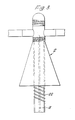
- Figure 8
- is a schematic representation of the arrangement of Figure 3 positioned adjacent the termination of a high voltage conductor at a transformer station, and including the earthing housing of Figure 7.
- Referring to Figure 1, a
housing 2 is made from an electrically-conductive polymeric material, and provides electrical protection for a fibre optic cable that extends along a high voltage conductor. The conductor and cable are shown in outline in Figure 1, and will be described in more detail with reference to Figure 2. Thehousing 2 comprises a first elongate part 4 that is open at each end and that has an upper generally right cylindrical portion 6 that continues downwards into a generally conical portion 8. Thehousing 2 has a second part 10, that provides a closure cap for the housing portion 6, and for this purpose the closure cap 10 has an internal thread and the cylindrical portion 6 has a mating external thread. - The cylindrical portion 6 is bifurcated at its open end so that a
slit 12 therein extends from the open end to generally circular openings in opposing side walls of the portion 6 that define a generallytubular passageway 14 therethrough. - Figure 2 shows the
housing 2 of Figure 1 mounted on a high voltageuninsulated overhead conductor 16 that has afibre optic cable 18 wound helically therearound. Thecable 18 may have any suitable construction as hereinbefore described. The bifurcated cylindrical portion 6 of thehousing 2 is spread apart so as to enlarge theslit 12 to an extent that theconductor 16 can pass therealong so as to be located within thehousing passageway 14. Thefibre optic cable 18 extends with theconductor 16 into thepassageway 14, but within thehousing 2 is lead off theconductor 16 and down through the open end of the conical housing portion 8. Aconductive mastic material 20 is wrapped around thecable carrying conductor 16 where it extends into, through, and out of thehousing 2 to prevent ingress of moisture into the housing along thepassageway 14. Theslit 12 is closed, and the housing cap 10 screwed on to the cylindrical portion 6, thereby sealing the top of thehousing 2. - Figure 1a shows one half 3 of a cast metal housing, that is secured to a corresponding half shell by screws or bolts so as to enclose the high voltage conductor. The housing formed from the half shells 3 functions electrically in the same way as the
housing 2 of Figure 1, but each half shell extends integrally above and below the conductor, one on each side thereof. Thus, the conductor extends through a channel 5, the fibre optic cable enters throughaperture 7, and internal ribs 9 provide for securing of a protective tube (not shown) for guiding the fibre optic cable transversely away from the conductor. - Referring to Figure 2a, the assembly has a
housing 21 that differs from thehousing 2 in its provision for entry of thefibre optic cable 18. In this arrangement, thecable 18 passes away from theconductor 16 at a distance of about 50mm before the conductor enters the housing. Thecable 18 then extends up to thehousing cap 23 that has anaperture 25 that allows the cable to pass down into thehousing 21. In another alternative configuration, aninlet aperture 27 for theoptical cable 18 is on the side of the cap, and the path of thecable 18 is then as shown by the broken lines in Figure 2a. Since thecable 18 enters thehousing 21 throughaperture conductor 16, as shown in Figure 2, there will be no chafing between thefibre optic cable 18,conductor 16 and the housing passage entrance. Furthermore, since thecable 18 is only away from theconductor 16 for a short distance before entering the conductive housing, no appreciable electrical stress is applied to the cable. - The configuration of the
housings fibre optic cable 18 extends out from the conical portion 8 thereof, the electric stress on the cable arising from the field associated with theconductor 16 is insufficient to cause damage to the cable or other adverse effects. To this end, parameters such as the length of thehousing 2 and the angle of the conical portion 8 are selected in accordance with the voltage rating of theconductor 16. For a 33kV conductor, for example, the length of the housing extending therebelow is typically 5cm to 8cm, with the conical surface of the housing making an angle of approximately 10° with the vertical (as seen in the Figures). - In the modified assembly shown in Figure 3, further, mechanical, protection of the
fibre optic cable 18 is provided on leaving the housing by enclosing it within aconvoluted tube 22 of electrically insulating polymeric material.Tube 22 engages internally with a threadedsection 23 of the cylindrical housing portion 6, and extends downwards from the open end of thehousing 2. - The further embodiment of the assembly shown in Figure 4 comprises a
housing 24 that differs from thehousing 2 in having an external screw-thread 26 at its lower open end, to which is externally threaded one end of aconvoluted tubing 28. - The protective assembly of Figure 4 has the advantage over the protective assembly of Figure 3 in that the
housing 24 does not shield thetubing 28 from water, and thus minimises the risk of dry-band formation on the outer surface of the combination of housing and tubing, which, in the assembly of Figure 3, could in some circumstances give rise to electrical damage to the tubing by way of tracking and erosion. - Figures 5a and 5b refer to alternative means to the
convoluted tubings fibre optic cable 50, which comprises five fibre optical fibres surrounding a strengthening member in a fully water-blocked construction, is embedded in a non-trackingouter jacket 52 that has sheds 54 on its outer surface. - Alternative housings to
housings - The
housing 56 of Figure 6a is coiled around a generally vertical axis, and is clamped at diametrically-opposedlocations conductor 62. Afibre optic cable 64 that extends helically along thecondcutor 62 is guided therefrom within thehousing 56 by a coiledmember 66, and passes to a cable splice enclosure, shown diagramatically at 68, that is mounted on thehousing 56. After splicing within theenclosure 68, the fibre optic cable leaves thehousing 56 in a convoluted and/or sheddedtube 70 as previously described. - The
housing 72 of Figure 6b differs from that of Figure 6a, in that it extends helically about an axis that is coincident with the overhead conductor. The detachment, splicing and subsequent guiding of the fibre optic cable is not shown, but may conveniently be as previously described. - It will be appreciated that each of the
enclosures housing 73 of Figure 6c overcomes this difficulty, since it is formed from a metal or fairly rigid conductive polymeric tubular member that is secured at its mid point, put into a U-shape and then wound about a mandrel such that the limbs of the U extend axially in opposite directions. Thehousing 73 is mounted on the conductor by looping the mid point thereover and subsequently rotating the entire housing about the conductor until gripping engagement is achieved at each end of the housing. - Figure 7 shows a
housing 74 that is suitable for attachment to the convoluted tubing that guides the fibre optic cable from the overhead conductor to its station at earth potential and serves as a stress control arrangement, an earthing medium and earth leakage current collector. It may also serve as an enclosure for a fibre optic splice or connector. - The
housing 74, shown open in Figure 7, comprises two generally semi-cylindrical brass half-shells 76 each of which has an integrally-ridgedneck portion 78 at each end for gripping theconvoluted tubing 80 that guides thefibre optic cable 82. A further pair of generally semi-sylindrical brass half-shells 84 are located within thehousing 74 and are clamped in contact with the half-shells 76 on closure of the housing. The non-trackingconvoluted tubing 80 extends into thehousing 74 and thefibre optic cable 82 exits therefrom and passes into a passageway formed by the half-shells 84. The larger upper part of the passageway encloses the fibre optic cable loosely, and is filled with a potting composition, and the narrower, lower part of the passageway grips the fibre optic cable firmly, but not so as to effect any damage thereto. Thus, thehousing 74 makes direct electrical contact with the outernon-tracking tubing 80 and with thefibre optic cable 82. A conductive connectingstud 86 is mounted on the outside of one of the half-shells 76, and a conductor (not shown) extends therefrom to a point at earth potential. - The
housing 74 contains a splice enclosure, shown diagrammatically at 88, and the fibre optic cable passes therefrom into a further portion of theconvoluted tubing 80 for onward transmission to a decoding station. - It is to be understood that in many instances, the fibre optic cable may not need to be protected, such as by a convoluted tube, and that this may be so whether or not the high voltage stress control arrangement is applied to the cable. Thus, referring to Figure 7, if there is no requirement for the protective insulating, non-tracking
convoluted tubing 80 to protect thefibre optic cable 82, then the outer pair ofhalf shells 76 of the earth leakagecurrent collector 74 may be dispensed with. In this case, thehalf shells 84 would be directly connected to earth potential. - Referring to Figure 8, a high voltage conductor 30 with the
fibre optic cable 18 spirally round thereon extends from one switchgear/transformer station (not shown), over a ten meterhigh support pole 32, and thence to a terminating switchgear/transformer station 34. The conductor 30 is secured to thepole 32 by tensioners 36 and is electrically isolated therefrom by insulators 38. Just before reaching thepole 32, thefibre optic cable 18 is lead away from the main conductor 30 along adrop wire 40, that at one end is crimped on to the conductor 30 and that at its other end is connected to asurge diverter 42 and thence to thepole 32 at earth potential. Thus, thedrop wire 40 is at the same voltage, 33kV say, as the conductor 30. Thefibre optic cable 18 is taken off thedrop wire 40 in advance of thesurge diverter 42 via the electrically-conductive housing convoluted tubing 22 that is secured to thepole 32. At the bottom end of the pole thefibre optic cable 18 leaves theconductive tubing 22 and enters into switchgear (not shown), which is at earth potential. This occurs as shown by means of thehousing 74. - It will be appreciated that usually the conductor 30 will be accompanied by two other conductors, thus providing a three-phase power supply, but only one of the conductors will, in general be required to carry a fibre optic cable.
- It is to be understood that features of fibre optic cables and cable arrangements mentioned herein may be combined together in any suitable combination to achieve particular objects.
- Attention is drawn to the parent application from which this present application is divided; this application is EP 83307592.2 (Publication NO. 0 112 163) which describes and claims a fibre optic cable suitable for operation in a region of high electric potential and for extending from said region to another region at an appreciably lower potential, said cable having an outer jacket of electrically-conductive material along one portion of its length intended to extend in said high potential region, and an outer jacket of substantially electrically non-tracking material along another portion of its length intended to extend in said lower potential region. Also, in a further Divisional Application No. 87202073.5 (Publication No. 0 303 740) there is described and claimed an arrangement comprising high voltage equipment and a fibre optic cable adjacent to or in contact with said equipment, wherein the cable is arranged to be connected to earth potential at at least one of its ends.
Claims (10)
- An arrangement comprising high voltage equipment, a fibre optic cable that is located in a region so as to be subject to the electric field of the equipment and to the flow of leakage current along the cable jacket, and electrically-conductive means mounted on the cable in said region so as to conduct to a point at earth potential leakage current flowing along the cable jacket.
- An arrangement as claimed in claim 1 wherein said electrically-conductive means comprises two inter-engaging half-shells.
- An arrangement as claimed in claim 2 wherein a pair of insulating half-shells mounted on the cable in abutment with the conductive half-shells such that the conductive half-shells are disposed in the direction of lower electric potential from the insulating half-shells, said insulating half-shells being formed from porcelain.
- An arrangement as claimed in any preceding claim wherein the fibre optic cable is guided to the electrically conductive means in a tubular member which is convoluted and/or has a shedded outer surface.
- An arrangement as claimed in claim 4 wherein the tubular member is of electrically insultating and non-tracking material.
- An arrangement as claimed in any preceding claim wherein the fibre optic cable extends along or alongside an elongate conductor which constitutes a high voltage equipment.
- An arrangement as claimed in any one of the preceding claims wherein a first portion of the fibre optic cable is subject to the electric field of the high voltage equipment and has an electrically conductive outer surface and wherein said first portion is joined to a second portion of the fibre optic cable that extends away from the said equipment with the outer surface of said second cable portion being substantially electrically non-tracking.
- An arrangement as claimed in claim 7 wherein the fibre optic cable comprises a substantially non-tracking outer jacket, a non-metallic strengthening member and at least one fibre optic element mounted within the jacket and protective filler material surrounding the strengthening member and the fibre optic element, said filler material being arranged to inhibit the formation of voids within the cable, or is arranged to inhibit transmission of moisture within the cable.
- A method of providing electrical protection for a fibre optic cable that is located in a region so as to be subject to the electric field of high voltage equipment and to the flow of leakage current along a jacket of the cable, wherein electrically-conductive means is mounted on the cable and is arranged to conduct a leakage current flowing along the cable jacket to a point at earth potential.
- A method as claimed in claim 9 wherein said electrically-conductive means comprises a housing which comprises two inter-engaging half-shells that are clamped together around the cable and wherein also two insulating half-shells are clamped together around the cable in abutment with said housing with the housing disposed in the direction of lower electric potential from the insulating half-shells.
Applications Claiming Priority (4)
| Application Number | Priority Date | Filing Date | Title |
|---|---|---|---|
| GB8235441 | 1982-12-13 | ||
| GB8235441 | 1982-12-13 | ||
| GB8311048 | 1983-04-22 | ||
| GB838311048A GB8311048D0 (en) | 1983-04-22 | 1983-04-22 | Fibre optic cable arrangements |
Related Parent Applications (1)
| Application Number | Title | Priority Date | Filing Date |
|---|---|---|---|
| EP83307592.2 Division | 1983-12-13 |
Publications (2)
| Publication Number | Publication Date |
|---|---|
| EP0426204A2 true EP0426204A2 (en) | 1991-05-08 |
| EP0426204A3 EP0426204A3 (en) | 1992-03-04 |
Family
ID=26284672
Family Applications (2)
| Application Number | Title | Priority Date | Filing Date |
|---|---|---|---|
| EP19900124925 Withdrawn EP0426204A3 (en) | 1982-12-13 | 1983-12-13 | Fibre optic cable arrangements |
| EP83307592A Expired - Lifetime EP0112163B1 (en) | 1982-12-13 | 1983-12-13 | Fibre optic cable arrangements |
Family Applications After (1)
| Application Number | Title | Priority Date | Filing Date |
|---|---|---|---|
| EP83307592A Expired - Lifetime EP0112163B1 (en) | 1982-12-13 | 1983-12-13 | Fibre optic cable arrangements |
Country Status (11)
| Country | Link |
|---|---|
| US (1) | US4772090A (en) |
| EP (2) | EP0426204A3 (en) |
| AT (1) | ATE123157T1 (en) |
| AU (1) | AU568618B2 (en) |
| CA (2) | CA1256727A (en) |
| DE (2) | DE3382788T3 (en) |
| GB (1) | GB2132788B (en) |
| IN (1) | IN162848B (en) |
| MY (1) | MY102488A (en) |
| NO (1) | NO171186C (en) |
| NZ (1) | NZ206555A (en) |
Cited By (2)
| Publication number | Priority date | Publication date | Assignee | Title |
|---|---|---|---|---|
| GB2256284B (en) * | 1991-06-01 | 1995-06-07 | Northern Telecom Ltd | Voltage stress protection device |
| WO2010086355A1 (en) * | 2009-01-30 | 2010-08-05 | Areva T&D Sas | Optical fibre protection for electrical insulators |
Families Citing this family (29)
| Publication number | Priority date | Publication date | Assignee | Title |
|---|---|---|---|---|
| GB8312892D0 (en) * | 1983-05-11 | 1983-06-15 | Raychem Ltd | Electrical insulator |
| GB8424584D0 (en) * | 1984-09-28 | 1984-11-07 | Bicc Plc | Overhead electric and optical transmission system |
| GB8428575D0 (en) * | 1984-11-12 | 1984-12-19 | Raychem Ltd | Electrical insulator |
| US4776665A (en) * | 1985-08-12 | 1988-10-11 | Siemens Aktiengesellschaft | Metal-free, self-bearing optical cable for high-tension overhead lines |
| US4770491A (en) * | 1986-05-19 | 1988-09-13 | Preformed Line Products Company | Dead end for fiber optic shield cable |
| US4832442A (en) * | 1987-07-17 | 1989-05-23 | United Ropeworks (U.S.A.) Inc. | Method and apparatus for aerial installation of fiber optic cables |
| GB2213952A (en) * | 1987-12-18 | 1989-08-23 | Focas Ltd | Optical fibre cable helically wound on electrical conductor |
| GB8817076D0 (en) * | 1988-07-18 | 1988-08-24 | Raychem Ltd | Oscillation suppression |
| GB8817075D0 (en) * | 1988-07-18 | 1988-08-24 | Raychem Ltd | Oscillation suppressor |
| US5018825A (en) * | 1989-06-14 | 1991-05-28 | Bicc Public Limited Company | Overhead optical transmission system |
| NL9001007A (en) * | 1990-04-26 | 1991-11-18 | Nkf Kabel Bv | COATING CONSTRUCTION, IN PARTICULAR FOR OPTICAL CABLES, FOR APPLICATION IN HIGH VOLTAGE ENVIRONMENTS. |
| US5315684A (en) * | 1991-06-12 | 1994-05-24 | John Mezzalingua Assoc. Inc. | Fiber optic cable end connector |
| GB2268284B (en) * | 1992-06-19 | 1996-01-24 | Bicc Plc | Optical cable helically wound on a suspended conductor |
| US5339378A (en) * | 1993-10-06 | 1994-08-16 | The United States Of America As Represented By The Secretary Of The Navy | Torque-balanced extendable fiber optic cable |
| FR2725302B1 (en) * | 1994-09-30 | 1997-03-14 | Sediver | AN ELECTRICAL ISOLATOR EQUIPPED WITH OPTICAL FIBERS AND ITS MANUFACTURING METHOD |
| US5647046A (en) * | 1995-11-20 | 1997-07-08 | Alcoa Fujikura Limited | Wedge deadend to support aerial cables |
| GB9613745D0 (en) * | 1996-07-01 | 1996-09-04 | Bicc Plc | Optical connection in HV line |
| DE19713308C2 (en) * | 1997-03-29 | 1999-10-28 | Alcatel Sa | Method for installing a telecommunication cable on a support cable and arrangement of a telecommunication cable on a support cable |
| DE19802191B4 (en) * | 1998-01-16 | 2004-12-23 | Siemens Ag | Optical current transformer with an optical fiber winding and method for its production |
| US6215940B1 (en) | 1998-06-01 | 2001-04-10 | 3M Innovative Properties Company | High voltage insulator for optical fibers |
| US6521835B1 (en) | 1999-06-14 | 2003-02-18 | K. & M. Realty Trust | Cable raceway for bridges and like structures with channel members having multiple degrees of freedom |
| US6389213B1 (en) | 2000-02-12 | 2002-05-14 | Alcoa Fujikura Limited | Deadend wedge design |
| US6831232B2 (en) | 2002-06-16 | 2004-12-14 | Scott Henricks | Composite insulator |
| US6776522B2 (en) * | 2002-10-09 | 2004-08-17 | Steven J. Syracuse | Apparatus and system for monitoring temperature of high voltage conductors |
| EP2469661A1 (en) * | 2010-12-21 | 2012-06-27 | Alcatel Lucent | Connector with enclosure for electrical contacting means of the connector |
| US8774587B1 (en) * | 2013-01-26 | 2014-07-08 | Optisense Network, Llc | Stress control structure for optical fibers in a high voltage environment |
| US9347973B2 (en) | 2013-05-15 | 2016-05-24 | Gridview Optical Solutions, Llc | Stress control assembly and methods of making the same |
| GB2535160A (en) * | 2015-02-09 | 2016-08-17 | Skf Ab | Power generator assembly for rotating applications |
| GB2585960B (en) | 2019-11-29 | 2022-04-20 | Afl Telecommunications Europe Ltd | A system for guiding a dielectric cable from phase-to-ground potential |
Citations (3)
| Publication number | Priority date | Publication date | Assignee | Title |
|---|---|---|---|---|
| FR2118113A1 (en) * | 1970-12-18 | 1972-07-28 | Gen Electric | |
| US3700900A (en) * | 1969-02-06 | 1972-10-24 | Arne J Herleikson | Dual purpose transmission line |
| DE2716922A1 (en) * | 1977-04-16 | 1978-10-19 | Rosenthal Technik Ag | HV outdoor insulator for signal transmission - is glass fibre reinforced plastics rods, in which some of reinforcing fibres are replaced by optical fibres with reflecting layer |
Family Cites Families (18)
| Publication number | Priority date | Publication date | Assignee | Title |
|---|---|---|---|---|
| US3485940A (en) * | 1967-12-26 | 1969-12-23 | Allis Chalmers Mfg Co | Post type modular insulator containing optical and electrical components |
| CH528067A (en) * | 1970-07-08 | 1972-09-15 | Siemens Ag | Outdoor-resistant insulation device |
| US3746870A (en) * | 1970-12-21 | 1973-07-17 | Gen Electric | Coated light conduit |
| GB1461540A (en) * | 1975-01-21 | 1977-01-13 | Standard Telephones Cables Ltd | Optical fibre cables |
| DK139490B (en) * | 1976-11-09 | 1979-02-26 | Nordiske Kabel Traad | Light conducting element for use in optical transmission. |
| DE2901872A1 (en) * | 1979-01-18 | 1980-07-31 | Siemens Ag | High voltage insulator with internal optical fibre - has optical fibre located between inner constructional layers for control transmission to power line |
| DE2929968A1 (en) * | 1979-07-24 | 1981-02-12 | Kabel Metallwerke Ghh | Glass optical waveguide fibre - which is continuously covered with foamed polymer and seam:welded metal tube to protect fibre against mechanical stress |
| DE3015732C2 (en) * | 1980-04-24 | 1983-06-01 | Philips Kommunikations Industrie AG, 8500 Nürnberg | Overhead cable with optical fibers arranged in its interior |
| JPS5744107A (en) * | 1980-08-29 | 1982-03-12 | Nippon Telegr & Teleph Corp <Ntt> | Optical fiber cable and its manufacture |
| ATE14942T1 (en) * | 1980-09-15 | 1985-08-15 | Bicc Plc | ELECTRICAL AND OPTICAL OVERLAND LINE. |
| GB2085188B (en) * | 1980-09-26 | 1984-05-23 | Bicc Ltd | An improved optical cable |
| AU543952B2 (en) * | 1981-06-03 | 1985-05-09 | Bicc Public Limited Company | Optical fibre joint for overhead transmission system |
| ZA824260B (en) * | 1981-06-18 | 1983-04-27 | Bicc Plc | Overhead electric transmission systems |
| ZA828667B (en) * | 1981-11-27 | 1983-09-28 | Bicc Plc | A flexible stranded body |
| AU553706B2 (en) * | 1982-02-18 | 1986-07-24 | Bicc Public Limited Company | Overhead electric transmission systems |
| JPS58162911A (en) * | 1982-03-23 | 1983-09-27 | Furukawa Electric Co Ltd:The | Optical communication line for joint use of overhead line |
| GB8424584D0 (en) * | 1984-09-28 | 1984-11-07 | Bicc Plc | Overhead electric and optical transmission system |
| US4610033A (en) * | 1984-12-14 | 1986-09-02 | Harvey Hubbell Incorporated | Insulator with fiber optic communication channel |
-
1983
- 1983-12-12 CA CA000443062A patent/CA1256727A/en not_active Expired
- 1983-12-12 AU AU22330/83A patent/AU568618B2/en not_active Expired
- 1983-12-12 NZ NZ206555A patent/NZ206555A/en unknown
- 1983-12-12 NO NO834562A patent/NO171186C/en unknown
- 1983-12-12 CA CA000443053A patent/CA1256726A/en not_active Expired
- 1983-12-13 DE DE3382788T patent/DE3382788T3/en not_active Expired - Lifetime
- 1983-12-13 EP EP19900124925 patent/EP0426204A3/en not_active Withdrawn
- 1983-12-13 AT AT87202037T patent/ATE123157T1/en not_active IP Right Cessation
- 1983-12-13 GB GB08333250A patent/GB2132788B/en not_active Expired
- 1983-12-13 IN IN1521/CAL/83A patent/IN162848B/en unknown
- 1983-12-13 EP EP83307592A patent/EP0112163B1/en not_active Expired - Lifetime
- 1983-12-13 DE DE8383307592T patent/DE3382345D1/en not_active Expired - Lifetime
-
1986
- 1986-09-05 US US06/904,578 patent/US4772090A/en not_active Expired - Lifetime
-
1987
- 1987-09-30 MY MYPI87002421A patent/MY102488A/en unknown
Patent Citations (3)
| Publication number | Priority date | Publication date | Assignee | Title |
|---|---|---|---|---|
| US3700900A (en) * | 1969-02-06 | 1972-10-24 | Arne J Herleikson | Dual purpose transmission line |
| FR2118113A1 (en) * | 1970-12-18 | 1972-07-28 | Gen Electric | |
| DE2716922A1 (en) * | 1977-04-16 | 1978-10-19 | Rosenthal Technik Ag | HV outdoor insulator for signal transmission - is glass fibre reinforced plastics rods, in which some of reinforcing fibres are replaced by optical fibres with reflecting layer |
Cited By (3)
| Publication number | Priority date | Publication date | Assignee | Title |
|---|---|---|---|---|
| GB2256284B (en) * | 1991-06-01 | 1995-06-07 | Northern Telecom Ltd | Voltage stress protection device |
| WO2010086355A1 (en) * | 2009-01-30 | 2010-08-05 | Areva T&D Sas | Optical fibre protection for electrical insulators |
| FR2941813A1 (en) * | 2009-01-30 | 2010-08-06 | Areva T & D Sa | OPTICAL FIBER PROTECTION FOR ELECTRIC ISOLATORS |
Also Published As
| Publication number | Publication date |
|---|---|
| GB8333250D0 (en) | 1984-01-18 |
| CA1256726A (en) | 1989-07-04 |
| NO171186C (en) | 1993-02-03 |
| ATE123157T1 (en) | 1995-06-15 |
| CA1256727A (en) | 1989-07-04 |
| EP0112163B1 (en) | 1991-07-17 |
| GB2132788B (en) | 1987-09-23 |
| GB2132788A (en) | 1984-07-11 |
| MY102488A (en) | 1992-06-30 |
| NO834562L (en) | 1984-06-14 |
| NO171186B (en) | 1992-10-26 |
| DE3382345D1 (en) | 1991-08-22 |
| EP0112163A3 (en) | 1985-10-23 |
| DE3382788D1 (en) | 1995-06-29 |
| AU568618B2 (en) | 1988-01-07 |
| DE3382788T3 (en) | 2001-11-15 |
| EP0112163A2 (en) | 1984-06-27 |
| NZ206555A (en) | 1988-03-30 |
| DE3382788T2 (en) | 1995-11-30 |
| EP0426204A3 (en) | 1992-03-04 |
| US4772090A (en) | 1988-09-20 |
| IN162848B (en) | 1988-07-16 |
| AU2233083A (en) | 1984-06-21 |
Similar Documents
| Publication | Publication Date | Title |
|---|---|---|
| EP0112163B1 (en) | Fibre optic cable arrangements | |
| US3307137A (en) | Conductor termination | |
| US5787217A (en) | Fiber optic ground wire cable | |
| US5936825A (en) | Rise pole termination/arrestor combination | |
| EP0172634A1 (en) | High voltage apparatus | |
| EP0253622B1 (en) | Terminated electric cable | |
| HUT63008A (en) | Optical cable and its protective cover | |
| CA2076543C (en) | Electrical protection apparatus | |
| US10957469B2 (en) | High voltage three-phase cable | |
| RU2484564C1 (en) | Device for connection between connective parts of electric power equipment | |
| EP0303740B1 (en) | An assembly comprising a high voltage conductor and a fibre optic cable | |
| GB2169099A (en) | Fibre optic cable for use at high voltage | |
| KR102309365B1 (en) | Apparatus for voltage withstand test | |
| GB2169100A (en) | Fibre optic cable for use at high voltage | |
| NZ216818A (en) | Optical fibre cable: earthing of h.v. resistant sheath | |
| US8774587B1 (en) | Stress control structure for optical fibers in a high voltage environment | |
| JPS59116704A (en) | Optical fiber cable and usage thereof | |
| EP1151340A1 (en) | Protection of dielectric cables | |
| Dyer | Insulated power cables used in underground applications | |
| KR200177486Y1 (en) | Insulated cable | |
| WO1992010772A1 (en) | An arrangement for use with high voltage equipment | |
| KR20210111531A (en) | Termination connection box for power cable | |
| AU644888C (en) | An electrical cable | |
| WO1995022777A1 (en) | Conductor termination | |
| WO1998000742A1 (en) | Optical connection in hv line |
Legal Events
| Date | Code | Title | Description |
|---|---|---|---|
| PUAI | Public reference made under article 153(3) epc to a published international application that has entered the european phase |
Free format text: ORIGINAL CODE: 0009012 |
|
| AC | Divisional application: reference to earlier application |
Ref document number: 112163 Country of ref document: EP |
|
| AK | Designated contracting states |
Kind code of ref document: A2 Designated state(s): AT BE CH DE FR IT LI NL SE |
|
| PUAL | Search report despatched |
Free format text: ORIGINAL CODE: 0009013 |
|
| AK | Designated contracting states |
Kind code of ref document: A3 Designated state(s): AT BE CH DE FR IT LI NL SE |
|
| 17P | Request for examination filed |
Effective date: 19920629 |
|
| 17Q | First examination report despatched |
Effective date: 19920825 |
|
| STAA | Information on the status of an ep patent application or granted ep patent |
Free format text: STATUS: THE APPLICATION IS DEEMED TO BE WITHDRAWN |
|
| 18D | Application deemed to be withdrawn |
Effective date: 19940322 |