EP0111652A2 - Anzeigerschutzvorrichtung gegen Feuchtigkeit und Vandalismus - Google Patents
Anzeigerschutzvorrichtung gegen Feuchtigkeit und Vandalismus Download PDFInfo
- Publication number
- EP0111652A2 EP0111652A2 EP83109618A EP83109618A EP0111652A2 EP 0111652 A2 EP0111652 A2 EP 0111652A2 EP 83109618 A EP83109618 A EP 83109618A EP 83109618 A EP83109618 A EP 83109618A EP 0111652 A2 EP0111652 A2 EP 0111652A2
- Authority
- EP
- European Patent Office
- Prior art keywords
- base
- cover
- pins
- enclosure
- channels
- Prior art date
- Legal status (The legal status is an assumption and is not a legal conclusion. Google has not performed a legal analysis and makes no representation as to the accuracy of the status listed.)
- Withdrawn
Links
- 238000007789 sealing Methods 0.000 claims abstract description 16
- 230000006378 damage Effects 0.000 claims abstract 4
- 230000002093 peripheral effect Effects 0.000 description 3
- XLYOFNOQVPJJNP-UHFFFAOYSA-N water Substances O XLYOFNOQVPJJNP-UHFFFAOYSA-N 0.000 description 3
- 229910001369 Brass Inorganic materials 0.000 description 2
- 239000010951 brass Substances 0.000 description 2
- 239000000463 material Substances 0.000 description 2
- 239000004033 plastic Substances 0.000 description 2
- 238000009825 accumulation Methods 0.000 description 1
- DHKHKXVYLBGOIT-UHFFFAOYSA-N acetaldehyde Diethyl Acetal Natural products CCOC(C)OCC DHKHKXVYLBGOIT-UHFFFAOYSA-N 0.000 description 1
- 125000002777 acetyl group Chemical class [H]C([H])([H])C(*)=O 0.000 description 1
- 238000005260 corrosion Methods 0.000 description 1
- 230000007797 corrosion Effects 0.000 description 1
- 230000000694 effects Effects 0.000 description 1
- 239000013536 elastomeric material Substances 0.000 description 1
- 239000011521 glass Substances 0.000 description 1
- 239000007769 metal material Substances 0.000 description 1
- 239000002991 molded plastic Substances 0.000 description 1
- 230000000737 periodic effect Effects 0.000 description 1
- 125000003011 styrenyl group Chemical class [H]\C(*)=C(/[H])C1=C([H])C([H])=C([H])C([H])=C1[H] 0.000 description 1
Images

Classifications
-
- G—PHYSICS
- G12—INSTRUMENT DETAILS
- G12B—CONSTRUCTIONAL DETAILS OF INSTRUMENTS, OR COMPARABLE DETAILS OF OTHER APPARATUS, NOT OTHERWISE PROVIDED FOR
- G12B9/00—Housing or supporting of instruments or other apparatus
- G12B9/02—Casings; Housings; Cabinets
- G12B9/04—Details, e.g. cover
-
- G—PHYSICS
- G01—MEASURING; TESTING
- G01D—MEASURING NOT SPECIALLY ADAPTED FOR A SPECIFIC VARIABLE; ARRANGEMENTS FOR MEASURING TWO OR MORE VARIABLES NOT COVERED IN A SINGLE OTHER SUBCLASS; TARIFF METERING APPARATUS; MEASURING OR TESTING NOT OTHERWISE PROVIDED FOR
- G01D11/00—Component parts of measuring arrangements not specially adapted for a specific variable
- G01D11/24—Housings ; Casings for instruments
Definitions
- This invention relates to tamperproof and moisture proof enclosures for data readout devices which are located remote from a measuring device, such as utility meters which are usually located within the house, the readout device being located on an exterior wall of the house.
- the enclosure disclosed in that patent is comprised of a base plate with a cover each of which have cooperating sealing means which provide a moisture proof chamber within the enclosure when the cover is on the base plate. It is necessary to prevent unauthorized access to the interior of the enclosure, otherwise the circuitry within the enclosure could be altered by some knowledgeable person to provide a spurious readout.
- the cover is secured to the base plate by means of four brass screws which are accessible from the exterior of the enclosure.
- a conventional means of preventing unauthorized access to the interior of the enclosure in such a design would be to provide holes in the screws through which a wire is passed, the ends of the wire being connected by a lead seal impressed thereon by the utility. Thus, removal of the cover would be impossible without affecting integrity of the seal.
- the cover and the base plate may be made of relatively inexpensive plastic material, such as a modified styrene based plastic, it is necessary that the screws be of some metallic material and preferably of brass to prevent corrosion.
- Such a means of securing the cover to the base plate is relatively expensive and, in order to to minimize the cost of producing and installing the enclosures while still maintaining security against unauthorized access to the interior, the instant invention provides an improved means for securing the cover to the base plate.
- the improved means of securing the cover to the base plate is comprised of forming rearwardly facing vertically extending channels on the back surface of the base plate.
- the cover is then provided with a peripheral wall portion which overlies the ends of these channels when the cover is secured on the base plate and ports are provided in the peripheral wall which register with each end of the channels.
- Locking pins are then inserted through the openings in the wall of the cover and the channels.
- One end of the locking pins has an abutment which prevents them from being withdrawn or removed from the channels in one direction.
- the other end of the locking pins extend beyond the enclosure proper and are provided with holes through which a wire may be threaded, the ends of the wire then being sealed together with a conventional utility seal.
- the pins may not be withdrawn without destroying the seal and, therefore, unauthorized access to the interior of the enclosure is thereby prevented at minimum expense.
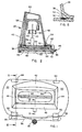
- an enclosure embodying the instant invention is comprised of a base 20 and an cover 22 secured to the base in a manner to be described.
- the base is formed of a molded plastic material and has a laterally extending front wall 24.
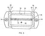
- Two spaced rearwardly opening vertically extending channels 26 and 28 are formed between vertically extending and rearwarding projecting walls 29 and 30 and walls 32 and 33, respectively.
- Holes 34 are provided at opposite ends of the base 20 to receive bolts or screws for securing the base to any desired support structure such as the wall of a residence.
- a U-shaped support bracket 36 is formed on the front wall 24 of the base and has a groove 38 for the reception of one end of a circuit board 40.
- the cover or housing 22 is formed of a top wall 42, two side walls 44 and 46 and a bottom wall 48, all of which converge from a rear wall 50 to form a chamber within the cover 22.
- a rectangular groove 52 is formed in the front face of the base in circumscribing relationship to the support ledge 36.
- a deformable seal 54 made of elastomeric material is received in groove 52.
- the seal 54 sealingly engages a sealing lip 58 formed on the interior of the cover at the juncture of the walls 42, 44, 46 and 48 with wall 50.
- the sealing lip 58 is coextensive with the seal 54 and is placed in sealing engagement therewith when the cover is secured in place as hereinafter described.
- an opening 60 for the reception of a closure member 62 for closing the chamber within the cover 22.
- An "0" ring 65 is received in a groove in a portion of the closure member which projects into the opening 60, the "0" ring having a slight interference fit with the wall surrounding the opening to hold the closure member in place and to provide a seal against leakage of moisture into the interior of the closure.
- Extending rearwardly from the opening 60 is a wall 64 at the rear edge of which at opposed points on the wall 64 project two pairs (only one pair shown) of oppositely spaced support clips 60 which support the front end of the circuit board 40 when the cover 22 is secured in position.
- a wall 70 extends rearwardly from wall 50 at the rear portion of the cover and circumscribes the entire rear portion of the cover 22.
- Vertically aligned ports 72 and 74 formed in wall 70 register with opposite ends of the channel 26, and vertically aligned ports 76 and 78 in wall 70 register with the ends of channel 28 when the cover 22 is placed over the base 20 so that the wall 70 on the cover 22 circumscribes the periphery of the base 20.
- two passages passing completely through both the wall 70 of the cover and the base are provided for the reception of two identical locking pins 80.
- the locking pins 80 which may be of glass reinfoced acetal, are comprised of a elongated shank portion 82 of generally rectangular cross section and a laterally extending head portion 84 at one end.
- the opposite end of the shank portion 82 is beveled as shown at 86 and has a hole 88 extending through it.
- Pressure pads 90 and 92 are formed on the front surface of the leg portion 82 which bear up against the front wall of channels 26 and 28 when the locking pins are in the channels to provide a suitable sealing pressure between the sealing lip 58 and the seal 54.
- the base 20 is first secured to the structure by means of bolts of screws passing through holes 31 at either side of the base.
- the rear end of the circuit board 40 is then inserted into the groove 38 formed in support bracket 36.
- the cover 22 is then placed over the base with the walls 70 closely circumscribing the peripheral wall of the base in which position the ports 72 and 74 and 76 and 78 are aligned with their respective channels 26 and 28.
- the support clips 60 engage the front portions of the circuit board to provide additional support for the board.
- the locking pins 80 are then inserted into passages provided by channels 26 and 28 and their aligned openings in the wall 70 of the cover.
- the nose or end portion of the pins 80 having the holes 88 will project outside of the enclosure beyond the lower run of wall 70 and the head portion 84 will be snugly received in the openings 72 and 76.
- the head portions 84 will overlie and abut against the front wall 24 on the base thereby preventing any further downward movement of the locking pins 80.
- a wire 96 may then be passed through the openings 88 in both pins and the ends of the wire sealed by a conventional utility seal 98, usually of lead, to prevent withdrawal of the pins in the upward direction.
- the closure member 62 When it is desired to obtain a reading from the meter to which the circuit board is electrically connected, the closure member 62 is removed and a readout gun having a receptacle is inserted into the opening at the front end of the enclosure into engagement with the terminal portions of the circuit board 40. After the data has been transferred into the accumulation device carried by the meter reader, the readout gun is withdrawn and the cover replaced.
Landscapes
- Physics & Mathematics (AREA)
- General Physics & Mathematics (AREA)
- Casings For Electric Apparatus (AREA)
- Connector Housings Or Holding Contact Members (AREA)
- Lock And Its Accessories (AREA)
Applications Claiming Priority (2)
| Application Number | Priority Date | Filing Date | Title |
|---|---|---|---|
| US06/436,255 US4520423A (en) | 1982-10-25 | 1982-10-25 | Tamperproof, moisture proof readout enclosure |
| US436255 | 1989-11-13 |
Publications (2)
| Publication Number | Publication Date |
|---|---|
| EP0111652A2 true EP0111652A2 (de) | 1984-06-27 |
| EP0111652A3 EP0111652A3 (de) | 1987-01-21 |
Family
ID=23731732
Family Applications (1)
| Application Number | Title | Priority Date | Filing Date |
|---|---|---|---|
| EP83109618A Withdrawn EP0111652A3 (de) | 1982-10-25 | 1983-09-27 | Anzeigerschutzvorrichtung gegen Feuchtigkeit und Vandalismus |
Country Status (3)
| Country | Link |
|---|---|
| US (1) | US4520423A (de) |
| EP (1) | EP0111652A3 (de) |
| CA (1) | CA1199073A (de) |
Cited By (1)
| Publication number | Priority date | Publication date | Assignee | Title |
|---|---|---|---|---|
| AT397740B (de) * | 1992-01-21 | 1994-06-27 | Siemens Ag Oesterreich | Vorrichtung zum abschirmen einer elektromagnetischen strahlung von einer elektronischen bauteile aufweisenden leiterplatte |
Families Citing this family (15)
| Publication number | Priority date | Publication date | Assignee | Title |
|---|---|---|---|---|
| USD296440S (en) | 1985-02-11 | 1988-06-28 | Delta Technical Services Limited | Data logger |
| USD298137S (en) | 1985-04-24 | 1988-10-18 | Datapaq Limited | Data logging device components |
| US4721478A (en) * | 1985-08-23 | 1988-01-26 | Thomas & Betts Corporation | Water sealed electrical connector |
| US4674763A (en) * | 1986-04-14 | 1987-06-23 | Albert Schlagenhaufer | Ski damping device |
| US5066906A (en) * | 1989-09-22 | 1991-11-19 | Landis & Gyr Metering, Inc. | Time of use register for use with a utility meter |
| US4994734A (en) * | 1989-09-25 | 1991-02-19 | General Electric Company | Register circuit board for electronic energy meter |
| US5298894A (en) * | 1992-06-17 | 1994-03-29 | Badger Meter, Inc. | Utility meter transponder/antenna assembly for underground installations |
| US6218995B1 (en) | 1997-06-13 | 2001-04-17 | Itron, Inc. | Telemetry antenna system |
| US6121562A (en) * | 1997-06-30 | 2000-09-19 | Siemens Energy & Automation, Inc. | Circuit breaker terminal shield with integral securing and installation and removal features method |
| US6144001A (en) * | 1997-06-30 | 2000-11-07 | Siemens Energy & Automation, Inc. | Circuit breaker terminal shield with integral securing and installation and removal features apparatus, means and system |
| AU1197899A (en) | 1997-10-24 | 1999-05-17 | Itron Inc. | Passive radiator |
| USD515042S1 (en) * | 2001-11-13 | 2006-02-14 | R & B Inc. | Top of a rocker switch and lens |
| DE10302114B4 (de) * | 2002-01-25 | 2009-02-26 | Black & Decker Inc., Newark | Handgeführtes, kraftgetriebenes Werkzeug mit vereinfachter Montage von Kupplungsmechanismus und Getriebe |
| US7066691B2 (en) * | 2002-01-25 | 2006-06-27 | Black & Decker Inc. | Power drill/driver |
| USD502149S1 (en) * | 2003-11-13 | 2005-02-22 | R&B, Inc. | Top of a rocker switch and lens |
Family Cites Families (10)
| Publication number | Priority date | Publication date | Assignee | Title |
|---|---|---|---|---|
| US863224A (en) * | 1907-01-08 | 1907-08-13 | Gen Electric | Electric meter. |
| US2794155A (en) * | 1956-01-04 | 1957-05-28 | Emerson Radio & Phonograph Cor | Handling and locking structure for switchboard panel units |
| US3011098A (en) * | 1957-08-30 | 1961-11-28 | Honeywell Regulator Co | Meter |
| US3334276A (en) * | 1966-09-29 | 1967-08-01 | Jess R Bateman | Meter switch and locking device |
| US3599047A (en) * | 1970-02-11 | 1971-08-10 | Harry Magarian | Lockable switch for power meters |
| US3675085A (en) * | 1971-08-13 | 1972-07-04 | Square D Co | Panel board for stacked electrical devices with sealing covers |
| US3748654A (en) * | 1972-01-21 | 1973-07-24 | Rockwell Mfg Co | Remote meter read-out station with pull-off cover |
| CH607550A5 (de) * | 1975-10-23 | 1978-12-29 | Wirth Gallo & Co | |
| JPS5524648A (en) * | 1978-08-09 | 1980-02-21 | Sumio Tomita | Meter sealer for electric and gas service |
| US4331012A (en) * | 1980-02-19 | 1982-05-25 | Swisher James A | Lockable meter retention ring |
-
1982
- 1982-10-25 US US06/436,255 patent/US4520423A/en not_active Expired - Lifetime
-
1983
- 1983-09-27 EP EP83109618A patent/EP0111652A3/de not_active Withdrawn
- 1983-09-30 CA CA000438168A patent/CA1199073A/en not_active Expired
Cited By (1)
| Publication number | Priority date | Publication date | Assignee | Title |
|---|---|---|---|---|
| AT397740B (de) * | 1992-01-21 | 1994-06-27 | Siemens Ag Oesterreich | Vorrichtung zum abschirmen einer elektromagnetischen strahlung von einer elektronischen bauteile aufweisenden leiterplatte |
Also Published As
| Publication number | Publication date |
|---|---|
| CA1199073A (en) | 1986-01-07 |
| EP0111652A3 (de) | 1987-01-21 |
| US4520423A (en) | 1985-05-28 |
Similar Documents
| Publication | Publication Date | Title |
|---|---|---|
| US4520423A (en) | Tamperproof, moisture proof readout enclosure | |
| US6982651B2 (en) | Automatic meter reading module | |
| US4295181A (en) | Module for an integrated circuit system | |
| DK34887A (da) | Udtagsdaase til koaksialkonnektorer | |
| EP0213574A3 (de) | Reserve-Batterie-Anordnung | |
| US4674778A (en) | Locking ring for electrical measuring device | |
| US6954144B1 (en) | Water pit transmitter assembly | |
| US5181166A (en) | Securing mechanism for an electricity metering device | |
| AU2002308535A1 (en) | Automatic meter reading module | |
| US4209154A (en) | Device for securing an apparatus in a wall | |
| US3748654A (en) | Remote meter read-out station with pull-off cover | |
| US4823572A (en) | Lockable terminal cover for bottom connected metering devices | |
| US5075182A (en) | Battery holder battery handle and battery indicator | |
| US6721184B1 (en) | Module for connecting actuators and/or sensors | |
| US5134544A (en) | Cable retaining mechanism for an electricity metering device | |
| US5196783A (en) | Vent for electricity metering device | |
| US4106344A (en) | Housing for electro-mechanical counter | |
| SI0752589T1 (en) | Electricity meter | |
| US5886297A (en) | Method and apparatus for sealing, on a non-permanent basis, a housing for enclosing electronic equipment | |
| FR2663472B1 (fr) | Dispositif de verrouillage de deux elements de boitier d'un connecteur electrique. | |
| JP3340235B2 (ja) | 火災報知設備用機器 | |
| JPH0130792Y2 (de) | ||
| EP0529757A1 (de) | Gehäuse | |
| US3739275A (en) | Weatherproof electrical meter | |
| US1995878A (en) | Meter casing |
Legal Events
| Date | Code | Title | Description |
|---|---|---|---|
| PUAI | Public reference made under article 153(3) epc to a published international application that has entered the european phase |
Free format text: ORIGINAL CODE: 0009012 |
|
| AK | Designated contracting states |
Designated state(s): DE FR GB NL |
|
| PUAL | Search report despatched |
Free format text: ORIGINAL CODE: 0009013 |
|
| AK | Designated contracting states |
Kind code of ref document: A3 Designated state(s): DE FR GB NL |
|
| 17P | Request for examination filed |
Effective date: 19870717 |
|
| 17Q | First examination report despatched |
Effective date: 19890306 |
|
| RAP1 | Party data changed (applicant data changed or rights of an application transferred) |
Owner name: M & FC HOLDING COMPANY, INC. |
|
| STAA | Information on the status of an ep patent application or granted ep patent |
Free format text: STATUS: THE APPLICATION IS DEEMED TO BE WITHDRAWN |
|
| 18D | Application deemed to be withdrawn |
Effective date: 19910329 |
|
| RIN1 | Information on inventor provided before grant (corrected) |
Inventor name: SUTHERLAND, RAY |