EP0111532B1 - Azimuth damper - Google Patents
Azimuth damper Download PDFInfo
- Publication number
- EP0111532B1 EP0111532B1 EP83901958A EP83901958A EP0111532B1 EP 0111532 B1 EP0111532 B1 EP 0111532B1 EP 83901958 A EP83901958 A EP 83901958A EP 83901958 A EP83901958 A EP 83901958A EP 0111532 B1 EP0111532 B1 EP 0111532B1
- Authority
- EP
- European Patent Office
- Prior art keywords
- damper
- fluid
- housing
- drum wheel
- gap
- Prior art date
- Legal status (The legal status is an assumption and is not a legal conclusion. Google has not performed a legal analysis and makes no representation as to the accuracy of the status listed.)
- Expired
Links
- 239000012530 fluid Substances 0.000 claims abstract description 30
- 238000013016 damping Methods 0.000 claims abstract description 28
- 239000000463 material Substances 0.000 claims abstract description 7
- 239000003822 epoxy resin Substances 0.000 claims abstract description 6
- 229920000647 polyepoxide Polymers 0.000 claims abstract description 6
- 239000000835 fiber Substances 0.000 claims abstract description 5
- 239000012528 membrane Substances 0.000 claims description 5
- 230000002093 peripheral effect Effects 0.000 claims description 4
- 230000003287 optical effect Effects 0.000 description 5
- OKTJSMMVPCPJKN-UHFFFAOYSA-N Carbon Chemical compound [C] OKTJSMMVPCPJKN-UHFFFAOYSA-N 0.000 description 2
- FYYHWMGAXLPEAU-UHFFFAOYSA-N Magnesium Chemical compound [Mg] FYYHWMGAXLPEAU-UHFFFAOYSA-N 0.000 description 2
- 229910052799 carbon Inorganic materials 0.000 description 2
- 229910052749 magnesium Inorganic materials 0.000 description 2
- 239000011777 magnesium Substances 0.000 description 2
- 229910000831 Steel Inorganic materials 0.000 description 1
- 206010044565 Tremor Diseases 0.000 description 1
- 230000001133 acceleration Effects 0.000 description 1
- 230000000694 effects Effects 0.000 description 1
- 229920002545 silicone oil Polymers 0.000 description 1
- 239000010959 steel Substances 0.000 description 1
Images
Classifications
-
- F—MECHANICAL ENGINEERING; LIGHTING; HEATING; WEAPONS; BLASTING
- F16—ENGINEERING ELEMENTS AND UNITS; GENERAL MEASURES FOR PRODUCING AND MAINTAINING EFFECTIVE FUNCTIONING OF MACHINES OR INSTALLATIONS; THERMAL INSULATION IN GENERAL
- F16F—SPRINGS; SHOCK-ABSORBERS; MEANS FOR DAMPING VIBRATION
- F16F15/00—Suppression of vibrations in systems; Means or arrangements for avoiding or reducing out-of-balance forces, e.g. due to motion
- F16F15/10—Suppression of vibrations in rotating systems by making use of members moving with the system
- F16F15/16—Suppression of vibrations in rotating systems by making use of members moving with the system using a fluid or pasty material
-
- F—MECHANICAL ENGINEERING; LIGHTING; HEATING; WEAPONS; BLASTING
- F16—ENGINEERING ELEMENTS AND UNITS; GENERAL MEASURES FOR PRODUCING AND MAINTAINING EFFECTIVE FUNCTIONING OF MACHINES OR INSTALLATIONS; THERMAL INSULATION IN GENERAL
- F16D—COUPLINGS FOR TRANSMITTING ROTATION; CLUTCHES; BRAKES
- F16D35/00—Fluid clutches in which the clutching is predominantly obtained by fluid adhesion
-
- Y—GENERAL TAGGING OF NEW TECHNOLOGICAL DEVELOPMENTS; GENERAL TAGGING OF CROSS-SECTIONAL TECHNOLOGIES SPANNING OVER SEVERAL SECTIONS OF THE IPC; TECHNICAL SUBJECTS COVERED BY FORMER USPC CROSS-REFERENCE ART COLLECTIONS [XRACs] AND DIGESTS
- Y10—TECHNICAL SUBJECTS COVERED BY FORMER USPC
- Y10T—TECHNICAL SUBJECTS COVERED BY FORMER US CLASSIFICATION
- Y10T74/00—Machine element or mechanism
- Y10T74/12—Gyroscopes
- Y10T74/1296—Flywheel structure
-
- Y—GENERAL TAGGING OF NEW TECHNOLOGICAL DEVELOPMENTS; GENERAL TAGGING OF CROSS-SECTIONAL TECHNOLOGIES SPANNING OVER SEVERAL SECTIONS OF THE IPC; TECHNICAL SUBJECTS COVERED BY FORMER USPC CROSS-REFERENCE ART COLLECTIONS [XRACs] AND DIGESTS
- Y10—TECHNICAL SUBJECTS COVERED BY FORMER USPC
- Y10T—TECHNICAL SUBJECTS COVERED BY FORMER US CLASSIFICATION
- Y10T74/00—Machine element or mechanism
- Y10T74/21—Elements
- Y10T74/2121—Flywheel, motion smoothing-type
- Y10T74/2122—Flywheel, motion smoothing-type with fluid balancing means
Definitions
- the present invention relates a fluid damper for damping aiming movements, for instance when tracking a target, comprising a substantially disc-shaped, cylindrical damper housing with a bottom part and a cover, a drum wheel supported for rotation in said housing and an inner gap spacing provided between the drum wheel and the damper housing which gap is filled with a highly viscous damping fluid.
- Waver, overshoot and other undesirable effects of a human operator should be eliminated by the damper. Even a. very small deviation of the guidance control signals in response to waver is capable of causing a deviation in the missile trajectory so that the missile passes at the side of the target.
- a fluid damper of the above mentioned kind which has a linearly increasing damping torque up to certain angular velocity, i.e. velocities up to approximately 30 mrad/s, but in which the linear increase of the damping torque is minimized for velocities exceeding said value to permit a rapid target acquisition.
- the maximum damping torque can be easily controlled by adjusting the clamping force of the slipping ring within the damper housing, i.e. between the bottom part and the cover of the housing.
- the slipping ring is made of material which is temperature stable and which can be made a high accuracy with respect to its dimensions.
- a material preferably could be carbon fibre reinforced epoxy resin material.
- an additional spacing is formed which communicates with said fluid gap spacing and which is separated from it by means of a membrane to even out pressure differences of the damping fluid by a relative movement of the membrane with respect to the damper housing.
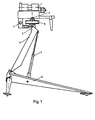
- Figure 1 schematically illustrates a target tracking device to be incorporated for instance in a weapon system in which the operator should keep the line of sight on a target with high aiming accuracy.
- the target tracking device further comprises an optical sight 1 through which the target and its background can be observed by the operator.
- the sight In order to make it possible to follow a moving target the sight is supported for rotation in both elevation and traverse, i.e. about a horizontal elevation axis 2 and a vertical azimuthal axis 3.
- the sight is aimed by the operator by means of a handle 4.
- the sight 1 is mounted on a support 5 provided with a tripode 6 supported on the ground.
- the support is provided with telescopic legs 7 to permit the support to be raised and lowered.
- an azimuth damper 8 is arranged between the support 5 and the sight 1.
- the damper comprises two main parts which are supported for rotation relative to each other about an axis of rotation which coincides with the azimuthal axis. The damper is described more in detail in connection with Fig. 2 below.
- a damper is required for eliminating undesired vibrations such as human trembling or waver and overshoot.
- a damper is used only for the azimuthal axis but of course a damper could be used also for the elevation axis.
- a damper for the azimuthal axis is more important as both the angular velocity and acceleration about the azimuthal axis exceeds the same for elevation axis.
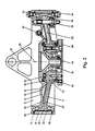
- FIG. 2 shows one example of a damper according to the invention.
- the damper comprises a substantially cylindrical, thin outer housing 9 in which a drum wheel 10 is supported for rotation.
- the housing 9 comprises a circular bottom part 11 and an upper circular cover 12 so that the damper housing 9 further comprises a slipping ring 14 integrated in the cylindric wall 13 of the housing which ring will be described more in detail below.
- the bottom part 11 and the cover 12 are held together by means of a number of screws 15, preferably three, which are distributed about the peripheral, cylindrical flange of the housing.
- the screws 15 are provided with a package of cup springs 16.
- the cover 12 of the damper housing is provided with means 17 for connecting the damper to the rotatable optical sight 1.
- the center of the cover is provided with a hollow shaft 18 on which the drum wheel 10 is supported for rotation by means of an angular contact ball bearing 19 as well as a nail bearing 20.
- the drum wheel 10 is provided with a corresponding inner hub 21 supported on the damper housing, three spokes 22 extending in the small annular gap of the housing and an outer ring 23 conforming to the slip ring 14 so that a small gap spacing 24 is formed between the outer cylindrical surface of the drum wheel and the slip ring.
- the spokes of the drum wheel are formed so that the drum wheel can be turned an angle of ⁇ 45° about the axis 25 before the movement is prevented by the joining screws 15.
- the inner hub 21 of the drum wheel is provided with a fastening plate 26 for mounting on the support 5 of the target tracking device.
- the desired damping of the aiming movements are provided by means of the annular gap 27 formed between the drum wheel and the damper housing which gap also includes said gap spacing 24 and which is filled with a high viscosity damping fluid.
- the fluid gap 27 is sealed by means of two annular, fluid-tight dynamic seals 28, 29 arranged between the hub 21 of the drum wheel and the cover and bottom part of the damper housing.
- the additional spacing is also provided with an airing screw 32.
- the peripheral flange of the damper housing is provided with screws 33, 34 for filling and draining the damping fluid.
- the outer part of the fluid gap is also sealed by means of two O-rings 35,36 disposed between the slipping ring and the cover and bottom part of the damper housing, respectively.
- the damper fluid e.g. silicone oil
- the dimension of the gap spacing 24 is approximately 0,2 millimetres at room temperature for producing a suitable damping torque.
- the housing and the drum wheel is preferably made of magnesium.
- the slipping ring is made of a carbon fibre reinforced epoxy resin, which material is light and strong and which can be made with a high precision with respect to its dimensions which is very important considering the very small dimension of the gap spacing. This material is also very stable for different temperatures, its thermal expansivity is practically zero for the temperature range in question. This will automatically give a temperature compensation as the gap is formed between the slipping ring (made of epoxy resin) and the drum wheel (made of magnesium).
- the described fluid damper has a linearly increasing damping torque to angular velocity for velocities up to approximately 40 mrad/s. For angular velocities exceeding this level the damping torque is limited and substantially constant due to the fact that the start friction of the slipping ring has been reached and the slipping ring starts to be rotated with respect to the other parts of the damper housing.
- the invention is not limited to said embodiment but can be varied within the scope of the accompanying claims. Even if the invention is described in connection with a light-weight portable weapon system is should be understood that the damper can be used also in other applications in which a damping of aiming movements is desired.
- the outer slipping ring 14 which is an important part of the damper is not necessarily made of a carbon-fibre reinforced epoxy resin only; in applications in which the requirement of temperature stability is not too high a steel slipping ring can be used.
Landscapes
- Engineering & Computer Science (AREA)
- General Engineering & Computer Science (AREA)
- Mechanical Engineering (AREA)
- Physics & Mathematics (AREA)
- Acoustics & Sound (AREA)
- Aviation & Aerospace Engineering (AREA)
- Fluid-Damping Devices (AREA)
- Vibration Prevention Devices (AREA)
- Other Liquid Machine Or Engine Such As Wave Power Use (AREA)
- Treatment Of Liquids With Adsorbents In General (AREA)
- Medicines Containing Material From Animals Or Micro-Organisms (AREA)
Applications Claiming Priority (2)
| Application Number | Priority Date | Filing Date | Title |
|---|---|---|---|
| SE8203657A SE444721B (sv) | 1982-06-14 | 1982-06-14 | Fluiddempningsorgan for dempning av riktrorelser |
| SE8203657 | 1982-06-14 |
Publications (2)
| Publication Number | Publication Date |
|---|---|
| EP0111532A1 EP0111532A1 (en) | 1984-06-27 |
| EP0111532B1 true EP0111532B1 (en) | 1987-09-30 |
Family
ID=20347054
Family Applications (1)
| Application Number | Title | Priority Date | Filing Date |
|---|---|---|---|
| EP83901958A Expired EP0111532B1 (en) | 1982-06-14 | 1983-06-14 | Azimuth damper |
Country Status (7)
| Country | Link |
|---|---|
| US (1) | US4572337A (esLanguage) |
| EP (1) | EP0111532B1 (esLanguage) |
| JP (1) | JPS59501119A (esLanguage) |
| DE (1) | DE3373935D1 (esLanguage) |
| NO (1) | NO152954C (esLanguage) |
| SE (1) | SE444721B (esLanguage) |
| WO (1) | WO1984000061A1 (esLanguage) |
Families Citing this family (3)
| Publication number | Priority date | Publication date | Assignee | Title |
|---|---|---|---|---|
| US8727658B2 (en) * | 2007-04-17 | 2014-05-20 | Ralph S. Norman | Pinless device for orienting a motorcycle stabilizer wiper |
| US20130199314A1 (en) * | 2012-01-26 | 2013-08-08 | Roller Bearing Company Of America, Inc. | Flywheel assembly for gyroscopic applications having ball bearing slug separators |
| US9303689B2 (en) | 2014-04-29 | 2016-04-05 | Roller Bearing Company Of America, Inc. | Non-rhythmically spaced rolling elements for reduction in bearing non-repeatable run-out |
Family Cites Families (7)
| Publication number | Priority date | Publication date | Assignee | Title |
|---|---|---|---|---|
| US1001065A (en) * | 1910-10-27 | 1911-08-22 | William H Mursch | Speed-regulating governor. |
| FR927547A (esLanguage) * | 1945-05-31 | 1947-11-10 | ||
| US2614896A (en) * | 1950-05-06 | 1952-10-21 | Pierce Mary Brush | Adjustable dampening bearing support |
| US2775317A (en) * | 1950-11-24 | 1956-12-25 | Sinisterra Federico | Shock and vibration damping device |
| GB1194185A (en) * | 1966-09-21 | 1970-06-10 | Holset Engineering Co | Improvements in and relating to Fluid Coupling Devices. |
| US3517946A (en) * | 1967-11-28 | 1970-06-30 | Houdaille Industries Inc | Fifth wheel viscous damper construction |
| US3907079A (en) * | 1973-10-31 | 1975-09-23 | Hughes Aircraft Co | Viscous fluid damper |
-
1982
- 1982-06-14 SE SE8203657A patent/SE444721B/sv not_active IP Right Cessation
-
1983
- 1983-06-14 US US06/597,157 patent/US4572337A/en not_active Expired - Fee Related
- 1983-06-14 EP EP83901958A patent/EP0111532B1/en not_active Expired
- 1983-06-14 DE DE8383901958T patent/DE3373935D1/de not_active Expired
- 1983-06-14 WO PCT/SE1983/000241 patent/WO1984000061A1/en not_active Ceased
- 1983-06-14 JP JP58502086A patent/JPS59501119A/ja active Granted
-
1984
- 1984-02-13 NO NO840519A patent/NO152954C/no unknown
Also Published As
| Publication number | Publication date |
|---|---|
| WO1984000061A1 (en) | 1984-01-05 |
| NO840519L (no) | 1984-02-13 |
| DE3373935D1 (en) | 1987-11-05 |
| US4572337A (en) | 1986-02-25 |
| SE444721B (sv) | 1986-04-28 |
| NO152954B (no) | 1985-09-09 |
| SE8203657L (sv) | 1983-12-15 |
| JPS59501119A (ja) | 1984-06-28 |
| EP0111532A1 (en) | 1984-06-27 |
| NO152954C (no) | 1985-12-18 |
| JPH0425479B2 (esLanguage) | 1992-04-30 |
Similar Documents
| Publication | Publication Date | Title |
|---|---|---|
| US3907079A (en) | Viscous fluid damper | |
| US5723923A (en) | Apparatus for providing torque and for storing momentum energy | |
| US20170048439A1 (en) | Gimbal Mount for a Sensor | |
| RU2432582C2 (ru) | Двухосная головка для ориентации с пьезоэлектрическим приводом | |
| NO145860B (no) | Antennestativsystem. | |
| GB2334333A (en) | Stabilized platform systems | |
| US4520973A (en) | Stabilized gimbal platform | |
| US3078728A (en) | Fluid driven gyroscope | |
| EP0111532B1 (en) | Azimuth damper | |
| US2852208A (en) | Method and apparatus for telemetering information from a missile in flight | |
| US3529477A (en) | Gyroscopic rotor suspension | |
| US3503663A (en) | Gyroscopically controlled motion compensator for optical devices | |
| US4177884A (en) | Damping mechanisms | |
| US2523267A (en) | Gyro-stabilized aerial camera mount | |
| GB2056109A (en) | Two-axis mounting structure for a telescope | |
| US3877552A (en) | Highly viscous fluid damper providing regulated non-linear damping for traversing units | |
| RU2114394C1 (ru) | Гироскопический прибор и способ регулировки его дрейфа | |
| US4671130A (en) | Drive assembly for astronomical telescope | |
| US4199762A (en) | Pedestal and gimbal assembly | |
| CA1201913A (en) | Azimuth damper | |
| US2385203A (en) | Electric turret traverse | |
| US2269103A (en) | Gyroscopic instrument | |
| US5027047A (en) | Half angle mechanism for a heliostat | |
| US4736916A (en) | Pan unit | |
| US4357107A (en) | Flight trajectory and observation theodolite |
Legal Events
| Date | Code | Title | Description |
|---|---|---|---|
| PUAI | Public reference made under article 153(3) epc to a published international application that has entered the european phase |
Free format text: ORIGINAL CODE: 0009012 |
|
| AK | Designated contracting states |
Designated state(s): BE CH DE FR GB LI NL |
|
| 17P | Request for examination filed |
Effective date: 19840208 |
|
| TCNL | Nl: translation of patent claims filed | ||
| DET | De: translation of patent claims | ||
| GRAA | (expected) grant |
Free format text: ORIGINAL CODE: 0009210 |
|
| AK | Designated contracting states |
Kind code of ref document: B1 Designated state(s): BE CH DE FR GB LI NL |
|
| REF | Corresponds to: |
Ref document number: 3373935 Country of ref document: DE Date of ref document: 19871105 |
|
| ET | Fr: translation filed | ||
| PLBE | No opposition filed within time limit |
Free format text: ORIGINAL CODE: 0009261 |
|
| STAA | Information on the status of an ep patent application or granted ep patent |
Free format text: STATUS: NO OPPOSITION FILED WITHIN TIME LIMIT |
|
| 26N | No opposition filed | ||
| PGFP | Annual fee paid to national office [announced via postgrant information from national office to epo] |
Ref country code: GB Payment date: 19930602 Year of fee payment: 11 |
|
| PGFP | Annual fee paid to national office [announced via postgrant information from national office to epo] |
Ref country code: FR Payment date: 19930616 Year of fee payment: 11 |
|
| PGFP | Annual fee paid to national office [announced via postgrant information from national office to epo] |
Ref country code: NL Payment date: 19930630 Year of fee payment: 11 |
|
| PGFP | Annual fee paid to national office [announced via postgrant information from national office to epo] |
Ref country code: BE Payment date: 19930702 Year of fee payment: 11 |
|
| PGFP | Annual fee paid to national office [announced via postgrant information from national office to epo] |
Ref country code: CH Payment date: 19930719 Year of fee payment: 11 |
|
| PGFP | Annual fee paid to national office [announced via postgrant information from national office to epo] |
Ref country code: DE Payment date: 19930824 Year of fee payment: 11 |
|
| PG25 | Lapsed in a contracting state [announced via postgrant information from national office to epo] |
Ref country code: GB Effective date: 19940614 |
|
| PG25 | Lapsed in a contracting state [announced via postgrant information from national office to epo] |
Ref country code: LI Effective date: 19940630 Ref country code: CH Effective date: 19940630 Ref country code: BE Effective date: 19940630 |
|
| BERE | Be: lapsed |
Owner name: A.B. BOFORS Effective date: 19940630 |
|
| PG25 | Lapsed in a contracting state [announced via postgrant information from national office to epo] |
Ref country code: NL Effective date: 19950101 |
|
| GBPC | Gb: european patent ceased through non-payment of renewal fee |
Effective date: 19940614 |
|
| NLV4 | Nl: lapsed or anulled due to non-payment of the annual fee | ||
| PG25 | Lapsed in a contracting state [announced via postgrant information from national office to epo] |
Ref country code: FR Effective date: 19950228 |
|
| REG | Reference to a national code |
Ref country code: CH Ref legal event code: PL |
|
| PG25 | Lapsed in a contracting state [announced via postgrant information from national office to epo] |
Ref country code: DE Effective date: 19950301 |
|
| REG | Reference to a national code |
Ref country code: FR Ref legal event code: ST |